EP1052865A1 - Station de base et procede de regulation de puissance d'emission - Google Patents
Station de base et procede de regulation de puissance d'emission Download PDFInfo
- Publication number
- EP1052865A1 EP1052865A1 EP99972825A EP99972825A EP1052865A1 EP 1052865 A1 EP1052865 A1 EP 1052865A1 EP 99972825 A EP99972825 A EP 99972825A EP 99972825 A EP99972825 A EP 99972825A EP 1052865 A1 EP1052865 A1 EP 1052865A1
- Authority
- EP
- European Patent Office
- Prior art keywords
- signal
- transmit power
- reception
- power control
- circuit
- Prior art date
- Legal status (The legal status is an assumption and is not a legal conclusion. Google has not performed a legal analysis and makes no representation as to the accuracy of the status listed.)
- Withdrawn
Links
Images


Classifications
-
- H—ELECTRICITY
- H04—ELECTRIC COMMUNICATION TECHNIQUE
- H04W—WIRELESS COMMUNICATION NETWORKS
- H04W52/00—Power management, e.g. Transmission Power Control [TPC] or power classes
- H04W52/04—Transmission power control [TPC]
- H04W52/18—TPC being performed according to specific parameters
- H04W52/28—TPC being performed according to specific parameters using user profile, e.g. mobile speed, priority or network state, e.g. standby, idle or non-transmission
- H04W52/283—Power depending on the position of the mobile
-
- H—ELECTRICITY
- H04—ELECTRIC COMMUNICATION TECHNIQUE
- H04W—WIRELESS COMMUNICATION NETWORKS
- H04W52/00—Power management, e.g. Transmission Power Control [TPC] or power classes
- H04W52/04—Transmission power control [TPC]
- H04W52/38—TPC being performed in particular situations
- H04W52/42—TPC being performed in particular situations in systems with time, space, frequency or polarisation diversity
Definitions
- the present invention relates to a base station apparatus having a function of detecting the position of a terminal apparatus in communication and its transmit power control method used in a radio communication system.
- a method of detecting the position of a terminal apparatus in communication by a base station apparatus in a radio communication system is disclosed in "Requirements and Objectives for 3G Mobile Services and System (ARIB) 1998.7.21", etc.
- FIG.1 is a system diagram showing a radio communication system including a base station apparatus having a position detection function.
- base station apparatus (BS) 1 detects the position of terminal apparatus (MS) 2 carrying out a radio communication, detects direction angle ⁇ of terminal apparatus 2 between the direction of arrival of a reception signal and the base station taking advantage of array antenna characteristics.
- This method of detecting the direction of the terminal apparatus is disclosed in the "Introductory Course for Adaptive Signal Processing Technology Using Array Antenna and High Resolution Arriving Wave Estimation", etc.
- base station apparatus 1 After detecting direction angle ⁇ of terminal apparatus 2 formed with the own station, base station apparatus 1 measures the distance between the own station and terminal apparatus 2. The method of measuring distance L between base station apparatus 1 and terminal apparatus 2 will be explained below using a slot timing chart in FIG.2.
- each apparatus improves its reception quality by carrying out RAKE combination that combines reception signals, which are direct and delay waves arriving at different times. Moreover, each apparatus performs transmit power control to reduce interference in reception processing from other stations while maintaining its desired reception quality.
- the conventional base station apparatus always performs transmit power control based on a power value of a signal resulting from RAKE combination of direct waves and delay waves, and so reception power of a direct wave is relatively small, resulting in a problem of failing to detect the position of the target terminal apparatus.
- the base station apparatus performs control during position detection so that the terminal apparatus simply increases transmit power, interference in the reception processing of signals by other stations increases, making it impossible to attain the desired reception quality. That is, it is desirable to reduce transmit power of each terminal apparatus to a necessary minimum in consideration of the system as a whole.
- the present invention attains the above object by carrying out transmit power control based on reception power of a signal combining direct wave and delay wave signals if position detection is correctly performed, and carrying out transmit power control only based on reception power of the direct wave signal if position detection is not correctly performed.
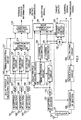
- FIG.3 is a block diagram showing a configuration of a base station apparatus according to an embodiment of the present invention.
- reception RF sections 104 to 106 amplify their respective signals received by antennas 101 to 103, convert their frequency to an intermediate frequency or baseband frequency and output the signals to matched filters 107 to 109.
- Matched filters 107 to 109 perform despreading on the output signals from reception RF sections 104 to 107 by their specific spreading codes and output the resulting signals to delay profile measuring circuit 110 and selection circuits 111 to 113.
- Delay profile measuring circuit 110 measures delay profiles (reception power at a predetermined time) of matched filters 107 to 109 and outputs the measurement result to timing detection circuit 111.
- FIG.4 illustrates an example of the delay profile measurement result.
- the horizontal axis expresses the time and vertical axis expresses power.
- there is not only a direct wave. which is a transmission signal directly arriving at the receiving side but also a delay wave arriving after being reflected by mountains and buildings, etc.
- FIG.4 shows that a direct wave signal of power p 0 arrives at time t 0 and a delay wave signal of power p1 arrives at time t 1.
- Timing detection circuit 111 detects the time at which a signal arrives from a delay profile and considers the signal that arrives first among the detected signals as a direct wave signal and outputs the information about the time at which the direct wave signal has arrived to selection circuits 112 to 114 and position detection circuit 116.
- Selection circuits 112 to 114 outputs the direct wave signals output from matched filters 107 to 109 to direction of arrival estimator 115 based on the information output from timing detection circuit 111.
- Direction of arrival estimator 115 estimates the direction of arrival of the reception signal from the output signals of selection circuits 112 to 114, detects the direction angle between the own station and terminal apparatus and outputs the information on the detected direction angle to position detection circuit 116.
- Position detection circuit 116 measures a propagation delay from the information on the time at which the direct wave signal has arrived and timing offset information and calculates the distance between the own station and terminal apparatus. Then, position detection circuit 116 outputs terminal position information indicating the distance between the own station and terminal apparatus and the direction angle to a central control station, which is not shown in the figure.
- Antenna duplexer 152 allows a same antenna to be used for both transmission and reception and outputs a signal received by radio by antenna 151 to the reception RF section 153 and outputs a transmission signal output from transmission RF section 165 to antenna 151.
- Reception RF section 153 amplifies the reception signal input from antenna duplexer 152 and converts its frequency to an intermediate frequency or baseband frequency and outputs the signal to matched filter 154.
- Matched filter 154 performs despreading by multiplying the output signal of reception RF section 153 by its specific spreading code and outputs the despread signal to delay profile measuring circuit 155 and selection circuit 157.
- Delay profile measuring circuit 155 measures a delay profile of the output signal of matched filter 154 and outputs the measurement result to timing detection circuit 156.
- Timing detection circuit 156 detects the time at which the signal arrives from the delay profile and outputs the information on the time at which each detected signal has arrived to selection circuit 157.
- Selection circuit 157 outputs the signal that arrives first among the output signals of matched filter 154 to channel estimator 158 as a direct wave signal and signals other the first arriving signal to channel estimator 159 as delay wave signals.
- Channel estimator 158 performs channel estimation of the direct wave signal and outputs the channel-estimated value to RAKE combination circuit 160 and transmit power control circuit 162.
- Channel estimator 159 performs channel estimation of the delay wave signals and outputs the channel-estimated values to RAKE combination circuit 160 and connection switch 161.
- RAKE combination circuit 160 corrects phase or amplitude variations due to fading by multiplying the direct wave signal by a complex conjugate of the channel-estimated value of channel estimator 157 and multiplying the delay wave signals by a complex conjugate of the channel-estimated value of channel estimator 158. Then, RAKE combination circuit 160 demodulates the corrected signals through RAKE combination and outputs the reception data to the central control station, which is not shown in the figure, and outputs a power control command to transmission RF section 165.
- Connection switch 161 controls whether or not to output the delay wave signals and channel-estimated value of channel estimator 159 to transmit power control circuit 162 based on a control signal from the central control station, which is not shown in the figure.
- Transmit power control circuit 162 corrects phase and amplitude variations of the input signals due to fading and then combines the signals and measures the level of reception power. If the measurement result falls below the target quality, transmit power control circuit 162 generates a power control command to increase the transmit power of the next uplink signal and otherwise generates a power control command to increase the transmit power of the next uplink signal and outputs the generated power control command to multiplexing circuit 163.
- Multiplexing circuit 163 multiplexes transmission data with the power control command output from transmit power control circuit 162 and outputs the multiplexed signal to modulation circuit 164.
- Modulation circuit 164 carries out primary modulation processing such as PSK and secondary modulation that multiplies specific spreading codes on the output signal of multiplexing circuit 163 and outputs the resulting signal to transmission RF section 165.
- Transmission RF section 165 carries out quadrature modulation and frequency conversion on the output signal of modulation circuit 164 and amplifies the output signal based on the power control command output from RAKE combination circuit 160 and transmits the signal by radio from antenna 151 via antenna duplexer 152.
- the signals received by antennas 101 to 103 are amplified by reception RF circuits 104 to 106 respectively and their frequency is converted to an intermediate frequency or baseband frequency.
- the output signals of reception RF sections 104 to 106 are despread by matched filters 107 to 109 using their specific spreading codes and output to delay profile measuring circuit 110 and selection circuits 112 to 114.
- Delay profile measuring circuit 110 measures delay profiles of the output signals of matched filters 107 to 109 and timing detection circuit 111 detects the time at which each reception signal arrives and outputs the information on the time at which the direct wave signal, which is the first arriving signal among the detected signals, has arrived to selection circuits 112 to 114 and position detection circuit 116.
- the direct wave signals are output to direction of arrival estimator 115 via selection circuits 112 to 114 based on the information output from timing detection circuit 111.
- Direction of arrival estimator 115 estimates the direction of arrival of the reception signal based on the direct wave signals, detects the direction angle of the terminal apparatus with respect to the own station and outputs information on the detected direction angle to position detection circuit 116.
- Position detection circuit 116 measures a propagation delay from information on the times of arrival of the direct waves and timing offset information and calculates the distance between the own station and terminal apparatus. Then, the terminal position information indicating the distance and direction angle between the own station and terminal apparatus is output to the central control station, which is not shown in the figure.
- timing detection circuit 111 may not be able to detect the time of arrival of the direct wave signal. In this case, the time of arrival of the delay wave signal is mistakenly detected as that of the direct wave, preventing the correct position of the terminal apparatus from being detected.
- the central control station decides that the reception quality has deteriorated preventing the correct position of the terminal apparatus from being detected. In this case, in order to increase transmit power of the uplink signal, the central control station sends a control signal to disconnect connection switch 161.
- the signal flow in the transmission/reception processing including transmit power control of the base station apparatus shown in FIG.3 will be explained below.
- the signal received by antenna 151 is input to reception RF circuit 153 through antenna duplexer 152, amplified and its frequency converted to an intermediate frequency or baseband frequency by reception RF circuit 153.
- the output signal of reception RF circuit 153 is subjected to despreading processing using a specific spreading code by matched filter 154 and output to delay profile measuring circuit 155 and selection circuit 157.
- Delay profile measuring circuit 155 measures the delay profile of the output signal of matched filter 154 and timing detection circuit 156 detects the time of arrival of each reception signal and the detected time of arrival of the signal is output to selection circuit 157.
- the signal arriving first of the detected signals is the direct wave signal and other signals are delay waves, the following processing is performed.
- the direct wave signal output from matched filter 154 is passed through selection circuit 157 and output to channel estimator 158, RAKE combination circuit 160 and transmit power control circuit 162.
- the delay wave signal output from matched filter 154 is passed through selection circuit 157 and output to channel estimator 159, RAKE combination circuit 160 and connection switch 161.
- Channel estimator 158 subjects the direct wave signal to channel estimation and channel estimator 159 subjects the delay wave signal to channel estimation and both channel-estimated values are output to RAKE combination circuit 160.
- RAKE combination circuit 160 corrects phase and amplitude variations due to fading and carries out RAKE combination and demodulation on each signal that has passed through selection circuit 157.
- the reception data is output to the central control station, which is not shown in the figure, and the transmit power control command is output to transmission RF section 165.
- connection switch 161 is output to transmit power control circuit 162 if connection switch 161 is connected by a control signal from the central control station.
- each input signal is subjected to correction of phase and amplitude variations due to fading and combined and the reception power level of the combined signal is measured. If the measurement result falls below the target quality, a power control command to increase the transmit power of the next uplink signal is generated and otherwise a power control command to increase transmit power of the next uplink signal is generated and the generated power control command is output to multiplexing circuit 163.
- transmit power control circuit 162 normally connects connection switch 161 and performs transmit power control based on reception power of a signal combining direct wave and delay wave signals. Then, if position detection is correctly carried out, there is no need to increase transmit power of the uplink signal, and so transmit power control circuit 162 leaves switch 161 connected thereby reducing interference signals at other base station apparatuses. On the other hand, if position detection is not carried out correctly, transmit power control circuit 162 disconnects connection switch 161 and carries out transmit power control only based on reception power of direct wave signals. As a result, transmit power of the uplink signal is increased until the reception power of direct waves reaches the target quality, which makes it possible to improve the reception quality, correctly detect direct waves and perform correct position detection.
- the transmission data of the downlink sent from the base station apparatus is multiplexed with the transmit power control command output from transmit power control circuit 162 by multiplexing circuit 163.
- the output signal of multiplexing circuit 163 is subjected to primary modulation processing such as PSK and secondary modulation processing with a specific spreading code multiplied by modulation circuit 164 and output to transmission RF section 165.
- the output signal of modulation circuit 164 is subjected to quadrature modulation, frequency conversion, etc. by transmission RF circuit 165 and amplified based on the transmit power control command output from RAKE combination circuit 160, and sent by radio from antenna 151 via antenna duplexer 152.
- the base station apparatus and transmit power control method of the present invention can perform transmit power control only based on the direct wave signals only when position detection is performed correctly, making reliable position detection compatible with reduction of interference in reception processing of signals of other stations.
- the central control station which is not shown in the figure, decides whether position detection is carried out correctly and controls connection switch 161, but this processing can also be performed by position detection circuit 116.
- RAKE combination circuit 160 performs RAKE combination only using the output of selection circuit 157, but it is also possible to perform RAKE combination using the outputs of selection circuits 112 to 114 in addition to the output of selection circuit 157.
Landscapes
- Engineering & Computer Science (AREA)
- Computer Networks & Wireless Communication (AREA)
- Signal Processing (AREA)
- Mobile Radio Communication Systems (AREA)
Applications Claiming Priority (3)
| Application Number | Priority Date | Filing Date | Title |
|---|---|---|---|
| JP33611098 | 1998-11-26 | ||
| JP33611098A JP3607512B2 (ja) | 1998-11-26 | 1998-11-26 | 基地局装置及び送信電力制御方法 |
| PCT/JP1999/006499 WO2000031999A1 (fr) | 1998-11-26 | 1999-11-22 | Station de base et procede de regulation de puissance d'emission |
Publications (2)
| Publication Number | Publication Date |
|---|---|
| EP1052865A1 true EP1052865A1 (fr) | 2000-11-15 |
| EP1052865A4 EP1052865A4 (fr) | 2005-06-22 |
Family
ID=18295803
Family Applications (1)
| Application Number | Title | Priority Date | Filing Date |
|---|---|---|---|
| EP99972825A Withdrawn EP1052865A4 (fr) | 1998-11-26 | 1999-11-22 | Station de base et procede de regulation de puissance d'emission |
Country Status (6)
| Country | Link |
|---|---|
| US (1) | US6628959B1 (fr) |
| EP (1) | EP1052865A4 (fr) |
| JP (1) | JP3607512B2 (fr) |
| CN (1) | CN1112824C (fr) |
| AU (1) | AU1185500A (fr) |
| WO (1) | WO2000031999A1 (fr) |
Families Citing this family (6)
| Publication number | Priority date | Publication date | Assignee | Title |
|---|---|---|---|---|
| JP3543959B2 (ja) | 2001-02-16 | 2004-07-21 | 日本電気株式会社 | 基地局 |
| US6794350B2 (en) | 2001-02-17 | 2004-09-21 | Novozymes A/S | Reduction of malodor from laundry |
| JP3989439B2 (ja) * | 2001-11-28 | 2007-10-10 | 富士通株式会社 | 直交周波数分割多重伝送方法 |
| US20040116122A1 (en) * | 2002-09-20 | 2004-06-17 | Interdigital Technology Corporation | Enhancing reception using intercellular interference cancellation |
| EP2112775B1 (fr) * | 2008-04-25 | 2018-06-06 | Telefonaktiebolaget LM Ericsson (publ) | Procédé et appareil pour la compensation du délai propagation dans un système de communication sans fil |
| WO2014194522A1 (fr) * | 2013-06-08 | 2014-12-11 | Telefonaktiebolaget L M Ericsson (Publ) | Suppression de brouillage de liaison montante dans un réseau de communication sans fil |
Family Cites Families (8)
| Publication number | Priority date | Publication date | Assignee | Title |
|---|---|---|---|---|
| US5293642A (en) * | 1990-12-19 | 1994-03-08 | Northern Telecom Limited | Method of locating a mobile station |
| TW351886B (en) * | 1993-09-27 | 1999-02-01 | Ericsson Telefon Ab L M | Using two classes of channels with different capacity |
| JPH0819035A (ja) | 1994-06-29 | 1996-01-19 | Nippon Telegr & Teleph Corp <Ntt> | 位置検出システム |
| JP3818702B2 (ja) | 1996-08-07 | 2006-09-06 | 松下電器産業株式会社 | Cdma無線伝送システム並びに該システムにおいて用いられる送信電力制御装置および送信電力制御用測定装置 |
| US5924040A (en) * | 1996-11-20 | 1999-07-13 | Telxon Corporation | Wireless communication system having base station with adjustable power transceiver for locating mobile devices |
| US6163696A (en) * | 1996-12-31 | 2000-12-19 | Lucent Technologies Inc. | Mobile location estimation in a wireless communication system |
| JP3299927B2 (ja) * | 1998-01-29 | 2002-07-08 | 沖電気工業株式会社 | 移動体通信システム、および移動局の位置推定方法 |
| US6490460B1 (en) * | 1998-12-01 | 2002-12-03 | Qualcomm Incorporated | Forward and reverse link power control using position and mobility information |
-
1998
- 1998-11-26 JP JP33611098A patent/JP3607512B2/ja not_active Expired - Fee Related
-
1999
- 1999-11-22 CN CN99802275.6A patent/CN1112824C/zh not_active Expired - Fee Related
- 1999-11-22 WO PCT/JP1999/006499 patent/WO2000031999A1/fr not_active Ceased
- 1999-11-22 AU AU11855/00A patent/AU1185500A/en not_active Abandoned
- 1999-11-22 US US09/600,285 patent/US6628959B1/en not_active Expired - Fee Related
- 1999-11-22 EP EP99972825A patent/EP1052865A4/fr not_active Withdrawn
Non-Patent Citations (2)
| Title |
|---|
| No further relevant documents disclosed * |
| See also references of WO0031999A1 * |
Also Published As
| Publication number | Publication date |
|---|---|
| EP1052865A4 (fr) | 2005-06-22 |
| US6628959B1 (en) | 2003-09-30 |
| WO2000031999A1 (fr) | 2000-06-02 |
| CN1288646A (zh) | 2001-03-21 |
| JP2000165320A (ja) | 2000-06-16 |
| AU1185500A (en) | 2000-06-13 |
| JP3607512B2 (ja) | 2005-01-05 |
| CN1112824C (zh) | 2003-06-25 |
Similar Documents
| Publication | Publication Date | Title |
|---|---|---|
| JP3290926B2 (ja) | 送信ダイバーシチ装置 | |
| EP1296465A1 (fr) | Systeme de calibrage pour un appareil recevant une antenne reseau | |
| EP0948145A2 (fr) | Appareil et procédé de communication radio avec de la réception à réseau d'antennes adaptatives | |
| EP1039663A1 (fr) | Dispositif de station de base, et proc d de radiocommunications | |
| EP1133072A1 (fr) | Terminal de communication et methode d'estimation de canal | |
| JP3858433B2 (ja) | パイロット信号検出方法及び受信機 | |
| US6721367B1 (en) | Base station apparatus and radio communication method | |
| EP1028544A1 (fr) | Dispositif de station de base et procede de communications radio | |
| US7599401B2 (en) | Transmission device and transmission method | |
| EP1096822A2 (fr) | Appareil et procédé pour transmission/réception en AMRT-DRT | |
| WO2005083897A1 (fr) | Appareil et procédé d’appareil de réception cdma | |
| EP1001558A2 (fr) | Dispositif terminal de communication et procédé de radiocommunication avec transmission en diversité | |
| AU743060B2 (en) | Base station and method of transmission power control | |
| EP1233543A1 (fr) | Dispositif de station de base et procede d'emission radioelectrique | |
| US7505509B2 (en) | Receiving communication apparatus using array antenna | |
| JP3583304B2 (ja) | 通信端末装置、基地局装置及び送信アンテナ切替方法 | |
| US6628959B1 (en) | Base station and method of transmission power control | |
| EP1209871A1 (fr) | Systeme et procede de presomption de canaux | |
| KR100690107B1 (ko) | Tdd 방식의 중계기에서 상하향링크 비율 절체 방법 | |
| EP1146668A1 (fr) | Terminal de communication, systeme de station de base et procede de commande de la puissance de transmission | |
| JPWO1995005037A1 (ja) | スペクトル拡散通信受信機および中継装置 | |
| EP1089476A1 (fr) | Recepteur a spectre etale et procede de reception de signaux | |
| MXPA00007166A (en) | Base station and method of transmission power control | |
| JPH11215037A (ja) | 双方向伝送装置 |
Legal Events
| Date | Code | Title | Description |
|---|---|---|---|
| PUAI | Public reference made under article 153(3) epc to a published international application that has entered the european phase |
Free format text: ORIGINAL CODE: 0009012 |
|
| 17P | Request for examination filed |
Effective date: 20000822 |
|
| AK | Designated contracting states |
Kind code of ref document: A1 Designated state(s): AT BE CH CY DE DK ES FI FR GB GR IE IT LI LU MC NL PT SE |
|
| AX | Request for extension of the european patent |
Free format text: AL;LT;LV;MK;RO;SI |
|
| RBV | Designated contracting states (corrected) |
Designated state(s): DE FR GB |
|
| A4 | Supplementary search report drawn up and despatched |
Effective date: 20050511 |
|
| RIC1 | Information provided on ipc code assigned before grant |
Ipc: 7H 04B 7/005 B Ipc: 7H 04B 7/26 B Ipc: 7H 04Q 7/34 A |
|
| GRAP | Despatch of communication of intention to grant a patent |
Free format text: ORIGINAL CODE: EPIDOSNIGR1 |
|
| STAA | Information on the status of an ep patent application or granted ep patent |
Free format text: STATUS: THE APPLICATION IS DEEMED TO BE WITHDRAWN |
|
| 18D | Application deemed to be withdrawn |
Effective date: 20060621 |