EP1052898B9 - Cryokonservierung und rückgewinnung von blutbestandteilen - Google Patents
Cryokonservierung und rückgewinnung von blutbestandteilen Download PDFInfo
- Publication number
- EP1052898B9 EP1052898B9 EP99965136A EP99965136A EP1052898B9 EP 1052898 B9 EP1052898 B9 EP 1052898B9 EP 99965136 A EP99965136 A EP 99965136A EP 99965136 A EP99965136 A EP 99965136A EP 1052898 B9 EP1052898 B9 EP 1052898B9
- Authority
- EP
- European Patent Office
- Prior art keywords
- solution
- blood component
- cryopreservation
- red blood
- osmolarity
- Prior art date
- Legal status (The legal status is an assumption and is not a legal conclusion. Google has not performed a legal analysis and makes no representation as to the accuracy of the status listed.)
- Expired - Lifetime
Links
- 238000005138 cryopreservation Methods 0.000 title claims abstract description 129
- 238000011084 recovery Methods 0.000 title claims abstract description 28
- 239000012503 blood component Substances 0.000 title claims description 102
- 210000003743 erythrocyte Anatomy 0.000 claims abstract description 219
- 239000000243 solution Substances 0.000 claims abstract description 218
- 239000012895 dilution Substances 0.000 claims abstract description 57
- 238000010790 dilution Methods 0.000 claims abstract description 57
- 238000005406 washing Methods 0.000 claims abstract description 53
- 230000035939 shock Effects 0.000 claims abstract description 38
- 230000002338 cryopreservative effect Effects 0.000 claims abstract description 24
- 238000007865 diluting Methods 0.000 claims abstract description 9
- 238000000034 method Methods 0.000 claims description 53
- 239000000819 hypertonic solution Substances 0.000 claims description 35
- 229940021223 hypertonic solution Drugs 0.000 claims description 34
- 230000000844 anti-bacterial effect Effects 0.000 claims description 13
- 238000005534 hematocrit Methods 0.000 claims description 12
- 239000000523 sample Substances 0.000 claims description 8
- XLYOFNOQVPJJNP-UHFFFAOYSA-N water Substances O XLYOFNOQVPJJNP-UHFFFAOYSA-N 0.000 claims description 8
- 239000012141 concentrate Substances 0.000 claims description 6
- 238000002156 mixing Methods 0.000 claims description 6
- 238000002360 preparation method Methods 0.000 claims description 6
- 238000004364 calculation method Methods 0.000 claims description 5
- 238000007710 freezing Methods 0.000 abstract description 9
- 230000008014 freezing Effects 0.000 abstract description 9
- 239000003761 preservation solution Substances 0.000 abstract description 8
- 230000008859 change Effects 0.000 abstract description 4
- PEDCQBHIVMGVHV-UHFFFAOYSA-N Glycerine Chemical compound OCC(O)CO PEDCQBHIVMGVHV-UHFFFAOYSA-N 0.000 description 87
- 210000004369 blood Anatomy 0.000 description 22
- 239000008280 blood Substances 0.000 description 22
- FAPWRFPIFSIZLT-UHFFFAOYSA-M Sodium chloride Chemical compound [Na+].[Cl-] FAPWRFPIFSIZLT-UHFFFAOYSA-M 0.000 description 18
- 230000008569 process Effects 0.000 description 17
- 239000006228 supernatant Substances 0.000 description 16
- 239000012530 fluid Substances 0.000 description 15
- 210000004027 cell Anatomy 0.000 description 14
- 238000000926 separation method Methods 0.000 description 14
- 239000011780 sodium chloride Substances 0.000 description 9
- 238000010586 diagram Methods 0.000 description 8
- 239000000306 component Substances 0.000 description 7
- 230000005484 gravity Effects 0.000 description 7
- 238000003860 storage Methods 0.000 description 7
- 238000012545 processing Methods 0.000 description 6
- 239000002699 waste material Substances 0.000 description 6
- WQZGKKKJIJFFOK-GASJEMHNSA-N Glucose Natural products OC[C@H]1OC(O)[C@H](O)[C@@H](O)[C@@H]1O WQZGKKKJIJFFOK-GASJEMHNSA-N 0.000 description 5
- 238000005119 centrifugation Methods 0.000 description 5
- 239000008103 glucose Substances 0.000 description 5
- 238000009987 spinning Methods 0.000 description 5
- IAZDPXIOMUYVGZ-UHFFFAOYSA-N Dimethylsulphoxide Chemical compound CS(C)=O IAZDPXIOMUYVGZ-UHFFFAOYSA-N 0.000 description 4
- 108010078678 Osmolite Proteins 0.000 description 4
- 210000000170 cell membrane Anatomy 0.000 description 4
- 230000008901 benefit Effects 0.000 description 3
- 230000005779 cell damage Effects 0.000 description 3
- 230000006378 damage Effects 0.000 description 3
- 230000001419 dependent effect Effects 0.000 description 3
- 230000006870 function Effects 0.000 description 3
- 239000000725 suspension Substances 0.000 description 3
- 229920001612 Hydroxyethyl starch Polymers 0.000 description 2
- 230000009471 action Effects 0.000 description 2
- 238000013019 agitation Methods 0.000 description 2
- 239000003146 anticoagulant agent Substances 0.000 description 2
- 229940127219 anticoagulant drug Drugs 0.000 description 2
- 238000013459 approach Methods 0.000 description 2
- 239000000356 contaminant Substances 0.000 description 2
- 230000012953 feeding on blood of other organism Effects 0.000 description 2
- 238000001914 filtration Methods 0.000 description 2
- 239000011521 glass Substances 0.000 description 2
- 229940050526 hydroxyethylstarch Drugs 0.000 description 2
- 238000001990 intravenous administration Methods 0.000 description 2
- 239000000203 mixture Substances 0.000 description 2
- 238000012986 modification Methods 0.000 description 2
- 230000004048 modification Effects 0.000 description 2
- 230000003287 optical effect Effects 0.000 description 2
- 230000002572 peristaltic effect Effects 0.000 description 2
- 238000004321 preservation Methods 0.000 description 2
- 238000005086 pumping Methods 0.000 description 2
- 239000000126 substance Substances 0.000 description 2
- 102000001554 Hemoglobins Human genes 0.000 description 1
- 108010054147 Hemoglobins Proteins 0.000 description 1
- 230000002745 absorbent Effects 0.000 description 1
- 239000002250 absorbent Substances 0.000 description 1
- 238000002617 apheresis Methods 0.000 description 1
- 239000007864 aqueous solution Substances 0.000 description 1
- 238000010420 art technique Methods 0.000 description 1
- 210000000601 blood cell Anatomy 0.000 description 1
- 230000017531 blood circulation Effects 0.000 description 1
- 210000001772 blood platelet Anatomy 0.000 description 1
- 230000036770 blood supply Effects 0.000 description 1
- 208000037887 cell injury Diseases 0.000 description 1
- 230000006727 cell loss Effects 0.000 description 1
- 239000006285 cell suspension Substances 0.000 description 1
- 238000004891 communication Methods 0.000 description 1
- 238000001514 detection method Methods 0.000 description 1
- 238000003113 dilution method Methods 0.000 description 1
- 239000006185 dispersion Substances 0.000 description 1
- 238000011049 filling Methods 0.000 description 1
- 239000012535 impurity Substances 0.000 description 1
- 230000036512 infertility Effects 0.000 description 1
- 210000000265 leukocyte Anatomy 0.000 description 1
- 238000011068 loading method Methods 0.000 description 1
- 230000007774 longterm Effects 0.000 description 1
- 238000007726 management method Methods 0.000 description 1
- 238000013178 mathematical model Methods 0.000 description 1
- 230000007246 mechanism Effects 0.000 description 1
- 239000012528 membrane Substances 0.000 description 1
- 238000012544 monitoring process Methods 0.000 description 1
- 230000010355 oscillation Effects 0.000 description 1
- 239000003755 preservative agent Substances 0.000 description 1
- 230000002335 preservative effect Effects 0.000 description 1
- 238000003825 pressing Methods 0.000 description 1
- 238000007639 printing Methods 0.000 description 1
- 108090000623 proteins and genes Proteins 0.000 description 1
- 102000004169 proteins and genes Human genes 0.000 description 1
- 230000009467 reduction Effects 0.000 description 1
- 230000003252 repetitive effect Effects 0.000 description 1
- 230000004044 response Effects 0.000 description 1
- 238000004062 sedimentation Methods 0.000 description 1
- 230000035945 sensitivity Effects 0.000 description 1
- 238000012546 transfer Methods 0.000 description 1
- 238000003466 welding Methods 0.000 description 1
Images



Classifications
-
- A—HUMAN NECESSITIES
- A01—AGRICULTURE; FORESTRY; ANIMAL HUSBANDRY; HUNTING; TRAPPING; FISHING
- A01N—PRESERVATION OF BODIES OF HUMANS OR ANIMALS OR PLANTS OR PARTS THEREOF; BIOCIDES, e.g. AS DISINFECTANTS, AS PESTICIDES OR AS HERBICIDES; PEST REPELLANTS OR ATTRACTANTS; PLANT GROWTH REGULATORS
- A01N1/00—Preservation of bodies of humans or animals, or parts thereof
- A01N1/10—Preservation of living parts
- A01N1/14—Mechanical aspects of preservation; Apparatus or containers therefor
- A01N1/142—Apparatus
- A01N1/143—Apparatus for organ perfusion
-
- A—HUMAN NECESSITIES
- A01—AGRICULTURE; FORESTRY; ANIMAL HUSBANDRY; HUNTING; TRAPPING; FISHING
- A01N—PRESERVATION OF BODIES OF HUMANS OR ANIMALS OR PLANTS OR PARTS THEREOF; BIOCIDES, e.g. AS DISINFECTANTS, AS PESTICIDES OR AS HERBICIDES; PEST REPELLANTS OR ATTRACTANTS; PLANT GROWTH REGULATORS
- A01N1/00—Preservation of bodies of humans or animals, or parts thereof
- A01N1/10—Preservation of living parts
Definitions
- the present invention relates generally to the storage of blood and blood components, and more specifically, to an improved system for adding a cryopreservation solution to red blood cells prior to freezing and for washing that solution from the red blood cells prior to their use.
- Human blood predominantly includes three types of specialized cells: red blood cells, white blood cells, and platelets. These cells are suspended in a complex aqueous solution of proteins and other chemicals called plasma. Although in the past blood transfusions have used whole blood, the current trend is to collect and transfuse only those blood components required by a particular patient. This approach preserves the available blood supply and in many cases is better for the patient, since the patient is not exposed to unnecessary blood components.
- Blood components are typically obtained from a donor following whole blood collection.
- a disposable blood collection set including a harness (e.g., tubing and connectors), a phlebotomy needle and one or more collection bags, is utilized to collect the whole blood from the donor.
- the phlebotomy needle is inserted into the donor's arm and blood flows under gravity into a collection bag which may contain an anticoagulant.
- the whole blood may be provided to a blood-processing machine for separation into one or more desired components.
- the machine includes a rotatable separation chamber which subjects the whole blood to many times the force of gravity, thereby separating the various blood components according to their densities.
- the more dense components such as red blood cells (RBCs)
- RBCs red blood cells
- the RBCs remaining in the separation chamber are removed.
- Blood components may also be obtained through apheresis in which whole blood from the donor is directly provided to the blood processing machine for separation and collection. With this method, any uncollected blood components may be returned directly to the donor.
- the collected blood components may then be stored before transfusion back to the donor or to some other patient.
- the individual blood components such as RBCs
- RBCs may be refrigerated at approximately 4°C for several days. Procedures are also known for freezing RBCs to further extend their shelf-life.
- RBCs may be stored at approximately -80°C or -160°C, depending on how they are prepared, for several years.
- RBCs are typically preserved with glycerol, prior to freezing, which crosses the cell membranes. Without glycerol, the RBCs would not survive the freezing process.
- U.S. Patent Reissue No. 33,924 to Valeri and entitled Apparatus and Method for Storing and Processing Blood discloses a method and apparatus for glycerolizing RBCs prior to freezing and also for washing the glycerol from thawed RBCs prior to transfusion.
- a three step process is used to introduce glycerol into a bag containing RBCs. First, the RBC bag is placed on a shaker platform operating at approximately 180 oscillations per minute, and 50 ml of a glycerol solution is gravity fed into the bag.
- the shaker platform is then turned off for about five minutes, allowing the RBCs and glycerol solution to equilibrate.
- the shaker platform is turned back on and a second volume of approximately 50 ml of glycerol solution is added to the bag.
- the shaker platform is turned off and the RBCs and glycerol solution are allowed to equilibrate for approximately two minutes.
- the bag is then removed from the shaker platform and a third volume of approximately 400 ml of glycerol solution is added while an operator applies manual agitation to the bag.
- the bag is then loaded onto a bag centrifuge device to concentrate the glycerolized RBCs. This results in the bag containing concentrated glycerolized RBCs and a supernatant glycerol solution. To remove the supernatant, the bag is placed in a plasma extractor. The bag may then be sealed in an overwrap bag and placed in a freezer operating at -80°C. As noted in the '924 patent, the entire process must be completed within four hours and results in glycerolized RBCs having a hematocrit of approximately 60%.
- the prior art glycerolization process is a time-consuming and labor intensive task. It also requires a highly skilled operator to ensure that the glycerol solution is administered in the proper doses at the appropriate times. Improper administration of glycerol, which is an osmolite, may damage the RBCs. In particular, the RBCs may suffer osmolarity shock causing cellular damage if the glycerol is introduced too quickly.
- the prior art method for washing the thawed, cryopreserved RBCs prior to transfusion is similarly time-consuming and labor intensive. More specifically, as described in the '924 patent, the bag of frozen, cryopreserved RBCs is placed in a heated bath for 20-25 minutes to thaw the RBCs. A machine, such as the Model 115 from Haemonetics Corp., which includes a shaker platform, a centrifuge drive unit and a wash bowl is then employed. First, 50 ml of a 12 % sodium chloride solution is gravity fed into the bag and mixed with the thawed RBCs by agitation of the shaker. The shaker is then turned off for two minutes to equilibrate the two solutions.
- a machine such as the Model 115 from Haemonetics Corp., which includes a shaker platform, a centrifuge drive unit and a wash bowl is then employed.
- 50 ml of a 12 % sodium chloride solution is gravity fed into the bag and
- shaker is then turned back on and 100 ml of a 0.9% sodium chloride and 0.2% glucose solution is gravity fed into the bag and mixed therein. Again, the shaker is stopped for about two minutes to permit the solutions to equilibrate. The shaker is turned on once again and 150 ml of the sodium chloride/glucose solution is added. The shaker is then turned off for two minutes.
- the introduction of each volume of wash solution to the thawed RBCs is also a delicate process.
- the wash solution is also an osmolite and thus may cause the RBC membranes to burst if it is added too quickly.
- the contents of the bag are then centrifuged to remove the wash solution and removed glycerol and the resulting RBCs are transferred to a collection bag. Just prior to transfusion, the washed RBCs are concentrated through centrifugation and removal of the supernatant. The final RBCs typically have a hematocrit below 40%.
- glycerol due to its high viscosity, glycerol cannot be gravity fed through an anti-bacterial filter. Thus, any contaminants entering the system are likely to reach the RBCs. Although this does not limit the length of time that the RBCs may remain frozen, it does require that the subsequently thawed red blood cells be utilized within 24 hours or discarded.
- WO 95/32624 describes a mathematical model and apparatus based upon the model to optimise protocols for the addition or removal of cryopreservative to or from biological cells.
- WO 99/08513 describes a process and apparatus in which cryopreservative is removed from samples with the use of turbulence and consecutive-dispersion around the cells.
- an apparatus for preparing a blood component for cryopreservation by mixing the blood component with a volume of cryopreservation solution that exposes the blood component to a risk of osmolarity shock comprising at least one pump that delivers the volume of cryopreservation solution in a substantially continuous flow to the blood component at an adjustable rate; and a controller operably coupled to the at least one pump so as to control the rate at which cryopreservation solution is delivered to the blood component, the controller configured to dynamically adjust the flow rate of the cryopreservation solution to reduce the risk of osmolarity shock to the blood component.
- a method for preparing a blood component for cryopreservation by mixing the blood component with a volume of cryopreservation solution that exposes the blood component to a risk of osmolarity shock comprising the steps of determining the volume of cryopreservation solution needed to obtain a desired concentration of cryopreservative within the blood component; providing the volume of cryopreservation solution in a substantially continuous flow to the blood component at an adjustable flow rate; and dynamically adjusting the flow rate of the cryopreservation solution to reduce the risk of osmolarity shock to the blood component.
- an apparatus for diluting a thawed, cryopreserved blood component with a volume of a dilution solution that exposes the blood component to a risk of osmolarity shock, in preparation for recovery of the blood component comprising means for providing the dilution solution to the blood component; at least one pump disposed in the providing means, that delivers the volume of dilution solution in a substantially continuous flow to the thawed blood component at an adjustable flow rate; and a controller operably coupled to the at least one pump so as to control the rate at which dilution solution is delivered to the blood component, the controller configured to dynamically adjust the flow rate of the dilution solution to reduce the risk of osmolarity shock to the blood component.
- a method for diluting a thawed, cryopreserved blood component with a volume of a dilution solution that exposes the blood component to a risk of osmolarity shock in preparation for recovery of the blood component, the method comprising the steps of providing the volume of dilution solution in a substantially continuous flow to the thawed blood component at an adjustable flow rate; dynamically adjusting the flow rate of the dilution solution to the thawed blood component to reduce the risk of osmolarity shock to the thawed blood component.
- an apparatus for preparing a blood component for cryopreservation by mixing the blood component with a volume of cryopreservation solution that exposes the blood component to a risk of osmolarity shock, and for diluting a thawed, cryopreserved blood component with a volume of a dilution solution that also exposes the blood component to a risk of osmolarity shock, in preparation for recovery of the blood component
- the apparatus comprising at least one pump that delivers either the volume of cryopreservation solution or the volume of dilution solution in a substantially continuous flow to the blood component at an adjustable rate; and a controller operably coupled to the at least one pump so as to control the rate at which either cryopreservation solution or dilution solution is delivered to the blood component, the controller configured to dynamically adjust the flow rate of either the cryopreservation solution or the dilution solution to reduce the risk of osmolarity shock to the blood component.
- the invention relates to a system for delivering a cryopreservation solution to red blood cells to permit long-term, frozen storage and for subsequently removing the cryopreservative during red blood cell recovery.
- the system preferably includes a controller that is operably connected to a shaker platform, a centrifuge drive unit and one or more variable-speed pumps.
- a display screen, printer and input device may also be connected to the controller.
- a cryopreservation harness is used to connect a cryopreservation solution to a unit of concentrated blood cells, which may be placed on the shaker platform.
- the controller is configured to monitor and govern the delivery of cryopreservation to the red blood cells via the pump.
- the controller periodically determines the amount of cryopreservation solution already added to the red blood cells and, based on this value, calculates a new cryopreservation solution flow rate in accordance with a novel algorithm.
- the algorithm provides a linear increase in red blood cell osmolarity that is selected to reduce the risk of shock and to minimize the processing time.
- the controller delivers cryopreservation solution at the calculated flow rates throughout the cryopreservation process.
- a recovery harness which includes a separation bowl and a wash solution, is similarly loaded onto the system.
- the thawed red blood cells are preferably placed on the shaker platform and coupled to both the wash solution and the separation bowl by two pumps.
- the controller is configured to monitor and govern the delivery of a first volume of wash solution to dilute the red blood cells.
- the controller dynamically adjusts the rate at which a dilution volume of wash solution is delivered to the red blood cells pursuant to a second novel algorithm.
- the second algorithm which is similarly dependent on a calculated volume of wash solution already delivered, provides a linear decrease in red blood cell osmolarity that is selected to minimize shock while reducing the dilution time.
- the controller delivers wash solution at the calculated flow rates throughout the dilution process. After the red blood cells have been diluted, they may be transferred to the separation bowl and additional wash solution may be introduced in order to wash any remaining cryopreservative from the cells.
- the cryopreservation solution is preferably pumped through an anti-bacterial filter before reaching the red blood cells.
- an anti-bacterial filter By filtering the cryopreservation solution and thereby removing potential contaminants, a significantly longer shelf-life of the subsequently recovered red blood cells is enabled.
- the thawed red blood cells are initially diluted with a volume of a hypertonic solution prior the introduction of the wash solution.
- the hypertonic solution has an osmolarity close to that of the thawed red blood cells and further reduces the risk of shock.
- cryopreservation and recovery processes are preferably performed to remove the debris resulting from the disintegration of weak cells unable to survive the recovery process and the washed red blood cells are suspended in a preservation solution to extend their shelf-life even further.
- Each step of the cryopreservation and recovery processes is automatically performed by the system under the management of the controller, significantly reducing error and the overall processing time.
- Fig. 1 is a block diagram of an improved cryopreservation/recovery system 100 in accordance with the present invention.
- the system 100 includes a controller 102, a shaker platform 104, a first pump 106, a centrifuge drive unit 108 and a second pump 110.
- the centrifuge drive unit 108 is preferably configured to receive a separation bowl as described below in connection with the washing of red blood cells.
- the controller 102 is operably connected to the shaker platform 104, the two pumps 106, 110 and the centrifuge drive unit 108 and may also be coupled to a plurality of input/output devices.
- controller 102 is preferably coupled to a display screen 112 for presenting information to a system operator and to a printer 114 for printing reports and other information.
- a system operator may supply information to the controller 102 by means of an input device 116 (e.g., a keyboard and/or mouse).
- the two pumps 106 and 110, the centrifuge drive unit 108, the display 112, the input device 116 and the controller 102 may all be disposed in a housing 118.
- the controller 102 includes one or more central processing units (CPU) and associated memory devices that may contain executable software instructions for implementing the steps of the invention as described below.
- the two pumps 106, 108 are preferably dual-direction, peristaltic pumps, providing approximately 1 ml of fluid per revolution.
- Each pump 106, 108 preferably includes an optical air detector (not shown) to determine whether air exists in the lines coupled to the pumps.
- Suitable components for the present invention are similar to the components in the Mobile Collection System (MCS) No. 8150 from Haemonetics Corp.
- the whole blood is collected from a donor in a primary bag containing an anticoagulant. It should be understood that the actual volume of whole blood that is collected and its corresponding hematocrit level may depend on the size of the separation bowl used during the recovery phase following cryopreservation.
- the whole blood may be stored in a conventional manner at approximately 4°C.
- the whole blood is centrifuged to separate the red blood cells from the other blood components in a conventional manner. For example, the whole blood may be centrifuged at 1615 times the force of gravity for four minutes to separate the red blood cells.
- the equipment and procedures for centrifuging whole blood are well-known to those skilled in the art and need not be described herein.
- the separated red blood cells may also be stored at approximately 4°C for a short time. Before the cryopreservation process begins, however, the RBCs and the cryopreservation solution are preferably warmed to room temperature (e.g., 22-30°C).
- a cryopreservation harness is preferably loaded onto the system 100. More specifically, a bottle of cryopreservation solution 120 is connected to the first pump 106 by means of a first line 122.
- a conventional spike connector and drip chamber (not shown) may be used to connect line 122 to bottle 120 and a clamp or pneumatic valve 124 that is moveable from an open to a closed position may be located in line 122 to control the flow of cryopreservation solution to the first pump 106.
- the cryopreservation solution is a glycerol solution having a concentration of 57.1% by weight, which is generally available in 500 ml glass bottles.
- the cryopreservation solution 120 may be suspended from an intravenous (IV) pole (not shown) attached to housing 118.
- a second line 126 connects the first pump 106 to a container 128 of red blood cells.
- the container 128 preferably includes a tube section 128a which may be connected to second line 126 by means of a sterile connection device (SCD) 130.
- SCD 130 such as the Model 312 from Terumo, is a well-known device for sterilely welding two tube segments together.
- a pressure probe 132 and an associated anti-bacterial filter 134 Disposed in the second line 126 are a pressure probe 132 and an associated anti-bacterial filter 134.
- the filter 134 is preferably a 0.2 ⁇ m hydrophilic filter, such as the Supor IV-3 Air Eliminating Filter from Pall/Gelman Sciences, Inc.
- the pressure probe 132 which is preferably located between the filter 134 and the SCD weld 130, supplies a corresponding pressure signal to the main controller 108 to not ensure that the SCD weld is not inadvertently resealed and that container 128 is not overfilled.
- a 0.2 ⁇ m hydrophilic filter 136 is also utilized at pressure probe 132.
- lines 122 and 126 are a single, continuous line loaded through first peristaltic pump 106.
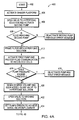
- Figs. 2A-B are flow diagrams of the steps 200 associated with the cryopreservation process in accordance with the present invention.
- the system operator After loading the cryopreservation harness onto the system 100 as described above, the system operator preferably enters the net weight and hematocrit level of the RBCs in container 128 into the system 100, as indicated at block 202, and places the container 128 onto the shaker platform 104, as indicated at block 204.
- the controller 102 then proceeds to calculate the volume of RBC concentrate within container 128 and also the desired volume of cryopreservation solution to be delivered to the RBC concentrate, as indicated by blocks 206 and 208.
- the volume of RBC concentrate, V i is preferably determined according to the following equation.
- V i NW i / [1.1 * Hct i / 100 + 1.026 * (1 - Hct i / 100)]
- NW i is the net weight of concentrated red blood cells prior to cryopreservation (grams)
- Hct i is the hematocrit level of the red blood cells before cryopreservation (%).
- the total volume of cryopreservation solution, V g to be mixed with the concentrated red blood cells is preferably computed in accordance with the following equation.
- V g C f / (C i -C f ) * V i * (1 - Hct i / 100 + Hct i * W /1000)
- C f is the target concentration of cryopreservative within the concentrated red blood cells following the cryopreservation process (%)
- C i is the concentration of cryopreservative in the cryopreservation solution (%)
- W is the volumetric percentage of water in the concentrated red blood cells (%).
- the values for W, C i and C f may be entered into the system 100 by the operator through input device 116, or the controller 102 may be pre-configured in a conventional manner with corresponding default values.
- the main controller 102 is pre-configured with W set to 72%, C i set to 57.1 % (the percentage of glycerol in its most commonly available form) and C f set to 40% which is the desired concentration of glycerol in the concentrated red blood cells for storage at -80°C.
- the operator pinches the drip chamber at bottle 120 to prime line 122 with an initial volume of cryopreservation solution, as shown at block 210.
- the valve 124 preferably remains closed at this point.
- the operator then engages the controller 102 through input device 116, as shown at block 212 (e.g., by pressing a "start" button).
- the controller 102 activates the first pump 106 and the shaker platform 104, which preferably operates at 3 Hz and 1.5 inches peak-to-peak amplitude, as indicated at block 214.
- the first pump 106 is preferably activated at an initial flow rate of 30 ml/minute and, as indicated at block 216, the controller 102 checks for fluid reaching pump 106 by monitoring the output of the corresponding the air detector.
- the controller 102 de-activates the pump 106 and issues an error message on display 112, as shown at block 218, indicating that the operator should check for occlusion in line 122. If fluid is detected, the controller 102 next monitors the increase in pressure in container 128 via pressure probe 132, as indicated at block 220.
- the controller 102 When the pressure exceeds 100 mm Hg, the controller 102 preferably opens valve 124, as shown by block 222, and begins counting the volume of cryopreservative solution delivered to container 128 by pump 106 based on the number of pump revolutions. If the pressure does not reach 100 mm Hg after approximately 5 ml of pumping action following the detection of fluid, the controller 102 preferably de-activates the pump 106 and issues an error message on display 112, as indicated by block 224. The error message may request the operator to check lines 122, 126 for leaks. Assuming the pressure reached the desired level and valve 124 was opened, the controller 102 proceeds to deliver the predetermined volume of cryopreservation solution, V g , to the red blood cells in container 128.
- the red blood cells Due to the large osmolarity differential between the 57.1 % glycerol solution (e.g., approximately 7230 mOsm/KgH 2 O) and the concentrated red blood cells in container 128 (e.g., approximately 320 mOsm/KgH 2 O), the red blood cells are highly susceptible to hypertonic shock and cell damage during cryopreservation. That is, even though glycerol actually diffuses across the cell membranes and is thus, in the strict sense, not a "true" osmolite, the high osmolarity differential between the RBCs and the glycerol solution causes water to be "pumped" out of the RBCs at a much higher rate than glycerol diffuses into the cells.
- the cell membranes are thus subject to high stresses, especially during the initial phases of the process, risking possible cell destruction.
- glycerol diffuses into the red blood cells, their osmolarity increases, thereby reducing the osmolarity differential with the cryopreservative solution and the consequent risk of shock.
- glycerol is initially added in small, fixed doses to limit possible RBC damage. This approach, however, is time-consuming, labor intensive and error prone.
- cryopreservation solution is delivered to the RBCs continuously.
- the present invention takes advantage of the increasing osmolarity of the red blood cells to increase the rate at which cryopreservative solution is delivered.
- the overall time needed to complete the process may be significantly reduced.
- the main controller 102 continuously calculates the desired flow rate of cryopreservation solution and dynamically adjusts the operating speed of pump 106 to achieve the desired flow rate.
- the cryopreservation flow rate, F g is preferably calculated according to the following equation.
- F g K [V i * (W * Hct i /100) + V g ] 2 / [V i * (W * Hct i / 100) * (O i - O g )]
- K is the selected rate of increase in osmolarity of the red blood cells (mOsm/Kg H 2 O/min.)
- V i is the volume of red blood cells before cryopreservation (ml)
- V g is the volume of cryopreservative solution that has already been added to the red blood cells prior to the current flow rate calculation (ml)
- O i is the osmolarity of the red blood cells before cryopreservation (mOsm/Kg H 2 O)
- O g is the osmolarity of the cryopreservation solution (mOsm/Kg H 2 O).
- an initial flow rate must be determined by controller 102 independent of equation (1).
- the initial flow rate, F o is preferably determined as follows.
- F o K * V i * (W * Hct i / 100) / (O i - O g )
- the volume of cryopreservation solution processed by the red blood cells at any given time, t is calculated as follows.
- V g K * V i * (1 - 0.28 * Hct i / 100) * t / (O i - O g - K * t)
- T the total time, needed to deliver the requisite volume of cryopreservation solution to the red blood cells.
- T V g * (O i - O g ) / K / [V i * (1 - 0.28 * Hct i /100) + V g ]
- Main controller 102 is preferably pre-configured in a conventional manner to determine each of these values according to the above-identified equations (3) - (6).
- parameters K, O i and O g may be entered by the operator or pre-configured within a memory device of controller 102.
- the controller 102 is pre-configured with K set to approximately 500, O i set to 320 and O g set to 7230.
- the controller 102 begins delivering cryopreservation solution from bottle 120 at the initial flow rate, F o , by setting the operating speed of pump 106 accordingly. Thereafter, the controller 102 continuously determines the amount of cryopreservation solution, V g , that has been added to container 128 using equation (5), as shown at block 228. Next, the controller 102 determines whether the computed volume of cryopreservation solution equals the desired volume selected to obtain the chosen concentration, as indicated at block 230. If not, controller 102 calculates a new flow rate, F g , from equation (3), as shown at block 232. The pump 106 is then adjusted to achieve this new flow rate, as shown at block 234. Controller 102 may wait until at least 1 ml of cryopreservation solution has been pumped at the initial flow rate, F o , before making its first calculation and corresponding adjustment.
- the controller 102 calculates new flow rate values, F g , and adjusts the pump speed on a real-time basis in accordance with a software loop executing the above-described process.
- controller 102 may be programmed to calculate a new flow rate F g at any predetermined time intervals. It should also be understood that if the change in flow rate is substantially less than smallest increment by which the pump may be adjusted (e.g., under 1 ⁇ 2 ml/min. for a pump adjustable in 1 ml/min. increments), no change in pump speed is made.
- controller 102 deactivates pump 106 and, shortly thereafter (e.g., 30 seconds later), stops the shaker 104, as indicated at block 236.
- the tube segment 128a from container 128 may then be cut from line 126 and heat sealed.
- a label identifying the unit of concentrated RBCs, the operator, donation center, date, initial blood unit net weight, initial blood unit hematocrit, initial blood unit volume, volume of cryopreservation solution added and the elapsed time of the cryopreservation process, among other information, may be printed by the controller 102 on printer 114, as indicated by block 238. The label may be affixed to the container 128 for identification purposes.
- the total volume of fluid in container 128 following the cryopreservation process is about 700-800 ml including about 200 ml of "absolute" RBCs (and a small volume of plasma) suspended in approximately 400-500 ml of cryopreservation solution.
- container 128 is subject to bag centrifugation by the system operator and the supernatant cryopreservation solution is removed in a conventional manner, leaving approximately 200 ml of absolute RBCs (approximately 300 ml total volume) to be frozen, as shown at block 240.
- Bag centrifugation which involves spinning the container at high rotational speeds, is well-known to those skilled in the art and need not be described in detail herein. This completes the cryopreservation process and the glycerolized-RBCs may be frozen at -80°C.
- the pressure in line 126 may need to be kept within certain limits.
- the pressure should not exceed 310 kN/m 2 (or 45 pounds per square inch).
- the maximum flow rate permitted by controller 102 should not exceed 80 ml/min.
- the controller 102 will nonetheless not exceed 80 ml/min.
- the present invention provides a substantially improved system for preparing red blood cells for cryopreservation.
- cryopreservation solutions besides glycerol
- HES hydroxyethyl starch
- DMSO dimethyl sulfoxide
- C f target concentrations of cryopreservative
- Fig. 3 is a block diagram of the system 100 configured to recover previously frozen red blood cells.
- system 100 includes a controller 102 operably coupled to two pumps 106, 108, a centrifuge drive unit 108, a shaker platform 104, a display 112 and a printer 114.
- An input device 116 allows a system operator to enter data and other information into the system 100.
- a separate recovery harness is preferably loaded onto system 100.
- three different solution bags 144, 146 and 148 are connected to pump 110 by means of a first line 150 and a three-way connector 152. Bag 144 preferably contains a preservative solution, such as AS-3 from Haemonetics Corp.
- Bag 146 preferably contains a washing solution (e.g., a 0.9% sodium chloride and 0.2% glucose solution) and bag 148 preferably contains a hypertonic solution (e.g., a 12% Sodium Chloride solution).
- the hypertonic solution contained in bag 148 preferably has an osmolarity almost equal to the osmolarity of the thawed RBCs in container 128.
- a corresponding pneumatic valve 154, 156, 158 which may be moved from an open to a closed position.
- a second line 160 connects pump 110 to a Y-connector 162 and preferably includes an anti-bacterial filter 164, which may be a 0.22 ⁇ m hydrophilic filter.
- a third line 166 which includes a two-way valve 168 is connected to one side of pump 106. Connected to one side of valve 168 by means of the SCD 130 is the tube segment 128a of container 128, which is again placed on the shaker platform 104. The red blood cells in container 128 are preferably thawed in a warm bath prior to being placed on shaker platform 104 as is well known.
- a final, recovered RBC collection bag 170 may be pre-connected to the other side of the two-way valve 168.
- third line 166 Disposed within third line 166 are the pressure probe 132 and associated filter 136.
- a fourth line 172 connects pump 106 to the Y-connector 162.
- the outlet of the Y-connector 162 is coupled by a fifth line 174 to an inlet 176 of a separation bowl 178 which may be loaded in the centrifuge drive unit 108.
- An outlet 180 of centrifugation bowl 178 may be connected to a waste bag 182 by means of a sixth line 184 having a pneumatic valve 185.
- a second pressure probe 186 and associated anti-bacterial filter 188 are preferably disposed in the sixth line 184.
- lines 150 and 160 and lines 172 and 166 are single, continuous lines loaded through corresponding pumps 110, 106.
- Separation bowl 178 may be a 275 ml spun volume, blow-molded bowl with a diverter and shortened plasma core, which may be similar to the series of 275 ml blow molded bowls from Haemonetics Corporation.
- the diverter (not shown) divides the interior of the bowl into two chambers (a separation chamber and a wash chamber), which facilitates the washing of red blood cells.
- the osmolarity of the thawed red blood cells should be on the order of 5200 mOsm/KgH 2 O.
- the osmolarity of a conventional washing solution (such as the 0.9% sodium chloride/ 0.2% glucose solution) is approximately 300 mOsm/KgH 2 O. This high osmolarity differential exposes the red blood cells to hypotonic shock (i.e., they rapidly take on water) and consequent cellular damage during the recovery process.
- the red blood cells are preferably initially diluted with a hypertonic solution having an osmolarity on the same order as the thawed red blood cells.
- a hypertonic solution having an osmolarity on the same order as the thawed red blood cells.
- the addition of the hypertonic solution also provides a slight reduction in red blood cell osmolarity. More specifically, the osmolarity of the thawed red blood cells following dilution with a hypertonic solution, O ph , is given by the following equation.
- O ph (V t * O t + V h * O h ) / (V t + V h )
- V t is the volume of the thawed red blood cells (ml)
- O t is the osmolarity of the thawed red blood cells (mOsm/KgH 2 O)
- V h is the volume of hypertonic solution added to the thawed red blood cells (ml)
- O h is the osmolarity of the hypertonic solution (mOsm/KgH 2 O).
- 50 ml of a 12 % Sodium Chloride hypertonic solution having an osmolarity of about 4000 mOsm/KgH 2 O is utilized to achieve a desirable osmolarity for diluted red blood cells of 4800-5300 mOsm/KgH 2 O as well as a desired supernatant buffer volume.
- one of the first steps of the recovery process is to mix approximately 50 ml of hypertonic solution with the thawed red blood cells.
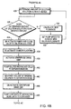
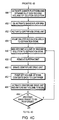
- Figs. 4A-D are flow diagrams of the steps 400 corresponding to the preferred red blood cell recovery process.
- the system operator preferably starts the system 100, as indicated at block 402.
- the controller 102 activates the shaker platform 104, which preferably operates at 3 Hz and 1.5 inches peak-to-peak amplitude, as indicated at block 404.
- valve 158 which is connected to the bag of hypertonic solution 148 (preferably loaded with 50 ml of a 12 % sodium chloride solution), is opened and pump 110 is activated to move fluid from right to left (relative to Fig.
- controller 102 also monitors the air detector associated with pump 110. In particular, controller 102 checks whether air is still being sensed despite approximately 5 pump revolutions at pump 110, as indicated at block 408. If so, controller 102 preferably de-activates pump 110 and issues an error message on display 112, as indicated at block 410. Once fluid is sensed at pump 110, controller 102 primes filter 164 with approximately 5 ml of hypertonic fluid by counting the fluid passing pump 110, as indicated at block 412.
- the controller 102 next activates pump 106 in a right to left direction (relative to Fig. 3) and moves valve 168 to provide fluid communication to container 128, as indicated at block 414.
- Hypertonic solution from bag 148 flows to pump 110, through filter 164 and Y-connector 162 to pump 106. From pump 106, the hypertonic solution flows through valve 168 and into container 128.
- controller 102 operates pump 110 at a flow rate of 150 ml/min. and pump 106 at approximately 5% less than the operating speed of pump 110. By running pump 106 at a 5% delta from pump 110, controller 102 ensures that little or no air is introduced into container 128.
- the controller 102 also monitors the pressure at pump 110 to ensure that it remains within certain limits, as indicated at block 416. If the pressure at pump 110 exceeds the range ⁇ 150 mm Hg, for example, controller 102 preferably de-activates both pumps 106, 110 and issues an error message, as shown at block 418. When the desired amount of hypertonic solution has been moved past pump 100 (e.g., 50 ml taking into account the volume in the various lines), valve 158 at the hypertonic solution bag 148 is closed, as indicated at block 420, completing the initial dilution of the thawed red blood cells with the hypertonic solution.
- pump 100 e.g., 50 ml taking into account the volume in the various lines
- the thawed RBCs are also diluted with a desired volume of washing solution from solution bag 146.
- the osmolarity of the thawed RBCs following dilution with hypertonic solution is approximately 4900 mOsm/KgH 2 O
- the osmolarity of washing solution such as 0.9% sodium chloride/ 0.2% glucose solution
- the flow rate, F s may be determined as a function of the washing solution already processed by the red blood cells according to the following equation.
- F s K D [V i * (W * Hct i /100) + V s ] 2 / [V i * (W * Hct i /100) * (O i -O s )
- K D is the desired osmolarity rate decrease (mOsm/KgH 2 O/min.)
- V i is the volume of the thawed red blood cells after dilution with the hypertonic solution (ml)
- Hct i is the hematocrit level of the thawed red blood cells after dilution with the hypertonic solution (%)
- V s is the volume of washing solution that has already been delivered to the thawed red blood cells (ml)
- O i is the osmolarity of the thawed red blood cells after dilution with the
- the initial washing solution flow rate is preferably determined as follows.
- F so K D * V i * (W * Hct i / 100) / (O i - O s )
- the volume of washing solution processed by the thawed red blood cells at any given time, t is calculated as follows.
- V s K D * V i * (W * Hct i / 100) * t / (O i - O s - K D * t)
- T the total time, T, needed to deliver the desired dilution volume of washing solution is calculated as follows.
- T V s * (O i - O s ) / K D / [V i * (W * Hct i / 100) + V s ]
- the osmolarity of the red blood cells, O s1 , after dilution with the desired volume, V s1 , of washing solution is provided by the following equation.
- O s1 (V h * O ph + V s1 * O s ) / (V h + V s1 )
- the red blood cells should be diluted with approximately 340 ml of washing solution, which is simply a function of the volume of container 128.
- controller 102 proceeds to deliver a total volume of 340 ml of washing solution to the red blood cells in accordance with the flow rate as periodically determined by equation (8).
- controller 102 upon closing valve 158, controller 102 opens valve 156 to the washing solution, as shown at block 422. Then, after the last of the hypertonic solution has reached container 128 and the washing solution is about to enter container 128 (i.e., sufficient volume has been moved past pump 110 to fill the intermediary lines and components), controller 102 preferably starts delivering washing solution to container 128 at the initial flow rate, F so , per equation (9), as indicated at block 424. Controller 102 also begins counting the total volume of washing solution being delivered to container 128 and may display this running value on display 112.
- the controller 102 continuously determines the amount of washing solution delivered to the thawed red blood cells, as indicated at block 426, and decides whether this amount equals the desired amount (e.g., 340 ml), as indicated at block 428. If not, controller 102 re-calculates the washing solution flow rate per equation (8) based on the current volume already delivered to the red blood cells, as indicated at block 430, and adjusts the corresponding speeds of pumps 110 and 106 to achieve the new flow rate, as indicated at block 432. Again, controller 102 preferably calculates new flow rate values, F s , and adjusts the pump speed on a real time basis (e.g., on the order of every 200 ms).
- Controller 102 also monitors the pressure at pump 106 to ensure that it remains within a selected range (e.g., ⁇ 150 mm Hg). If the pressure exceeds the selected range, controller 102 preferably de-activates pumps 106 and 110 and issues a warning or error message on display 112.
- a selected range e.g., ⁇ 150 mm Hg
- controller 102 When the desired amount of washing fluid has been delivered to the red blood cells in container 128, controller 102 preferably de-activates the pumps 106, 110 and shuts off the supply of washing solution from bag 146 by closing valve 156, as indicated at block 434. Controller 102 preferably allows the shaker platform 104 to continue operating for an additional 10 seconds after de-activating the pumps 106, 110, as indicated at block 436.
- the container 128 now includes the volume of thawed red blood cells plus the dilution volumes of hypertonic and washing solutions from bags 148, 146, respectively.
- System 100 preferably separates the lighter phases of this solution (i.e., the supernatant) from the red blood cells through centrifugation.
- controller 102 activates the centrifuge drive unit 108 to spin centrifuge bowl 178 at approximately 8000 rpm, as indicated at block 438.
- Controller 102 next activates pump 106 in a left to right direction (relative to Fig. 3) to pump red blood cells from container 128 to centrifuge 178, as shown at block 440.
- Pump 106 may be operated at the maximum bowl 178 filling rate (e.g., 200 ml/min.). Controller 102 also counts the volume of fluid entering the centrifuge bowl 178 based on pump revolutions. Rotation of the centrifuge bowl 178 drives the heavier red blood cells outwardly against the inner surface of the bowl, while the supernatant (including hypertonic and wash solutions) collect in an annular zone located radially inward from the red blood cells. This supernatant is forced through the outlet 180 of bowl 178 and is collected in waste bag 182.
- Bowl 178 preferably includes an optical line sensor (not shown) which monitors the fluid exiting the bowl 178 to ensure that the more light absorbent red blood cells are not being discharged into the waste bag 182.
- a volume (e.g., 100 ml) of washing solution is preferably added through operation of pump 110 at a constant flow rate (e.g., 50 ml/min.), as indicated at block 442.
- a corresponding volume (e.g., 100 ml) of supernatant, which includes hypertonic and wash solutions, is also removed.
- Controller 102 then de-activates centrifuge drive unit 108, stopping the bowl 178 and allowing the RBCs and remaining supernatant to re-mix, as indicated at block 444, for approximately 45 seconds.
- the contents of the separation bowl 178 are preferably pumped back to container 128 through operation of pump 106 in a right-to-left direction (relative to Fig. 3), as indicated at block 446.
- the pump speed may be about 200 ml/min.
- the controller 102 preferably activates the shaker platform 104 and delivers a second volume of wash solution from wash bag 146 to container 128, as indicated at block 448. More specifically, the controller 102 preferably delivers approximately 410 ml of wash solution, pursuant to the initial and dynamic flow rate equations (9) and (8), respectively, as described above in connection with steps 424 and 432.
- the 410 ml of wash solution is simply a function of the capacity of container 128.
- container 128 has about 250-260 ml (i.e., the bowl volume) of fluid an additional 410 ml will keep the total volume below its capacity (e.g., 800 ml).
- controller deactivates the shaker platform 104, as indicated by block 450.
- the RBCs have now been diluted with one volume of hypertonic solution and two volumes of wash solution. The osmolarity of RBCs should be close to the osmolarity of wash solution.
- the next step is to wash the remaining cryopreservative out of the RBCs.
- the system 100 performs five (5) separate washing phases with the diluted red blood cells in the centrifuge bowl 178.
- the washing phases are utilized to complete removal of cryopreservative within the RBCs and to remove any debris (e.g., broken cell membranes, free hemoglobin, etc.) from weak cells unable to survive the freezing and recovery process intact.
- the volume of washing solution, its flow rate into the bowl 178 and the equilibrium time, as discussed, below are selected so that the osmolarity of RBCs evolves linearly over time.
- the controller 102 activates the centrifuge drive unit 108 so as to rotate bowl 178 at approximately 8000 rpm, as indicated at block 452, and pumps the diluted red blood cells from container 128 to the centrifuge bowl 178 through pump 106, as indicated at block 454.
- the pump speed may be on the order of 150 ml/min. at the beginning and 50 ml/min. at the end of the transfer.
- the controller 102 proceeds to deliver approximately 150 ml of washing solution from bag 146 to spinning bowl 178, as indicated at block 456.
- the washing solution may be delivered at approximately 50 ml/min.
- controller 102 activates the braking mechanism of the centrifuge drive unit 108 and the bowl 178 is stopped, as shown at block 460. It typically takes approximately 15 seconds to stop the bowl 178 from spinning.
- the bowl 178 preferably remains stationary for a predetermined equilibrium delay period (e.g., 45 seconds). The equilibrium delay allows the RBC osmolarity to continue to evolve.
- a set volume (e.g., 20 ml) of the bowl's contents may be pumped to the container 128 by pump 106, as indicated at block 462. This allows the bowl head to be re-aspirated and limits red blood cell loss during the next wash phase.
- Controller 102 next activates the centrifuge drive unit 108 to spin the bowl 178 at approximately 8000 rpm for a preset amount of time (e.g., 60 seconds) and returns the previously removed volume (20 ml) of fluid to the bowl 178, as indicated by block 464. This completes the first wash phase.
- Controller 102 next determines whether another wash phase is to be performed, as shown at block 466. If so, 102 controller preferably repeats steps 456 to 466. As indicated, in the preferred embodiment, five wash phases are performed on the diluted red blood cells.
- the second wash phase preferably utilizes approximately 300 ml of washing solution delivered at about 100 ml/min., while the third through fifth wash phases each utilize 300 ml of washing solution delivered at 150 ml/min.
- controller 102 proceeds to suspend the washed red blood cells in a preservation solution.
- the suspension of washed red blood cells may performed in multiple phases. More specifically, with bowl 178 spinning at approximately 8000 rpm, a preset volume (e.g. 80 ml) of a preservation solution from bag 144 is delivered to the bowl 178 preferably at a constant flow rate (e.g., 80 ml/min.), as shown at block 468.
- the centrifuge drive unit 108 is then braked, stopping the bowl 178, as indicated at block 470.
- the valve 185 to the waste bag 182 is preferably closed during braking, except for the last preservation cycle when it is opened, thereby allowing additional supernatant to be removed and collected in the waste bag 182.
- the bowl 178 is also allowed to remain stationary for a predetermined dwell time (e.g., 45 seconds), as indicated at block 472. This dwell time allows the contents of the bowl (i.e., washed red blood cells and preservation solution) to inter-mix and achieve a homogenous red blood cell suspension.
- the centrifuge drive unit 108 is re-started and bowl 178 is spun at approximately 8000 rpm long enough to achieve adequate red blood cell sedimentation (e.g., 60 seconds), as shown at block 474.
- Controller 102 next determines whether the suspension of washed red blood cells is complete, as shown at block 476. If not, controller 102 preferably repeats steps 468 to 476 as described above. In the preferred embodiment, the controller 102 performs one preservation cycle. At this point, the red blood cells have been washed of cryopreservative and are suspended in a preservation solution. Controller 102 de-activates the centrifuge drive unit 108, as shown at block 478, and then pumps the washed and suspended RBCs into the final collection bag 170, as indicated at block 480. The RBCs are moved by operating pump 106 in a right-to-left direction (relative to Fig. 3) at a flow rate of approximately 20 ml/min.
- the final, recovered RBCs may be stored at 4 °C for approximately two (2) weeks before being utilized. This extended storage time far exceeds the storage times available with the prior art devices, which are typically limited to twenty-four hours.
- cryopreservation and recovery processes described herein may be implemented and performed separately.
Landscapes
- Life Sciences & Earth Sciences (AREA)
- Zoology (AREA)
- Engineering & Computer Science (AREA)
- Dentistry (AREA)
- General Health & Medical Sciences (AREA)
- Wood Science & Technology (AREA)
- Health & Medical Sciences (AREA)
- Environmental Sciences (AREA)
- External Artificial Organs (AREA)
- Medical Preparation Storing Or Oral Administration Devices (AREA)
- Medicines Containing Material From Animals Or Micro-Organisms (AREA)
- Agricultural Chemicals And Associated Chemicals (AREA)
- Micro-Organisms Or Cultivation Processes Thereof (AREA)
Claims (36)
- Vorrichtung zur Aufbereitung einer Blutkomponente zur Kryokonservierung durch Vermischen der Blutkomponente mit einem Volumen einer Kryokonservierungslösung, welche die Blutkomponente der Gefahr eines Osmolaritätsschocks aussetzt, wobei die Vorrichtung aufweist:mindestens eine Pumpe, die das Kryokonservierungslösungsvolumen im wesentlichen im Dauerzufluß mit einstellbarer Geschwindigkeit zu der Blutkomponente fördert;einen funktionsfähig mit der mindestens einen Pumpe gekoppelten Regler zu Regelung der Geschwindigkeit, mit der die Kryokonservierungslösung zu der Blutkomponente gefördert wird, wobei der Regler so konfiguriert ist, daß das Risiko eines Osmolaritätsschocks für die Blutkomponente vermindert wird.
- Vorrichtung nach Anspruch 1, die ferner ein antibakterielles Filter aufweist, das zwischen der Kryokonservierungslösung und der Blutkomponente angeordnet ist.
- Vorrichtung nach Anspruch 2, wobei der Regler die Durchflußgeschwindigkeit bei der Kryokonservierung so einstellt, daß ein im wesentlichen linearer Osmolaritätsanstieg der Blutkomponente aufrechterhalten wird.
- Vorrichtung nach Anspruch 3, wobei der Regler ferner so konfiguriert ist, daß er wiederholt den der Blutkomponente zugesetzten Anteil der Kryokonservierungslösung bestimmt, auf der Basis des ermittelten Anteils der Kryokonservierungslösung eine neue Durchflußgeschwindigkeit berechnet und die mindestens eine Pumpe so einstellt, daß sie die Kryokonservierungslösung mit der neuen Durchflußgeschwindigkeit fördert.
- Vorrichtung nach Anspruch 4, wobei der Regler auf Echtzeitbasis den Anteil der Kryokonservierungslösung bestimmt, die neue Durchflußgeschwindigkeit berechnet und die mindestens eine Pumpe einstellt.
- Vorrichtung nach Anspruch 5, wobei der Regler ferner so konfiguriert ist, daß er ein Volumen der Kryokonservierungslösung bestimmt, das zum Erzielen einer gewünschten Konzentration der Kryokonservierungslösung innerhalb der Blutkomponente erforderlich ist.
- Vorrichtung nach Anspruch 6, wobei ein Schlauch die Kryokonservierungslösung mit der Blutkomponente verbindet und in dem Schlauch förderseitig von der mindestens einen Pumpe eine Drucksonde angeordnet ist, wobei die Drucksonde ein entsprechendes Drucksignal zum Regler übermittelt, der ferner so konfiguriert ist, daß er die mindestens eine Pumpe deaktiviert, wenn das Drucksignal einen vorgegebenen Schwellwert übersteigt.
- Vorrichtung nach Anspruch 1, wobei die Blutkomponente aus roten Blutzellen besteht und der Regler so konfiguriert ist, daß er die Geschwindigkeit der mindestens einen Pumpe so einstellt, daß die Durchflußgeschwindigkeit der Kryokonservierungslösung im wesentlichen durch die folgende Gleichung gegeben ist:
K die gewählte Anstiegsgeschwindigkeit der Osmolarität der roten Blutzellen ist,
Vi das Volumen der roten Blutzellen ist;
W der Wasseranteil in Volumenprozent in den roten Blutzellen ist,
Hcti der Hämatokritspiegel der roten Blutzellen vor der Kryokonservierung ist,
Vg das Volumen der Kryokonservierungslösung ist, das den roten Blutzellen bereits vor der aktuellen Berechnung der Durchflußgeschwindigkeit zugesetzt wurde,
Oi die Osmolarität der roten Blutzellen vor der Kryokonservierung ist, und
Og die Osmolarität der Kryokonservierungslösung ist. - Vorrichtung nach Anspruch 8, wobei der Regler so konfiguriert ist, daß er zunächst die Geschwindigkeit der mindestens einen Pumpe so einstellt, daß die Anfangsdurchflußgeschwindigkeit der Kryokonservierungslösung im wesentlichen durch die folgende Gleichung gegeben ist:
- Vorrichtung nach Anspruch 9, wobei der Regler ferner so konfiguriert ist, daß er das Volumen Vi der roten Blutzellen im wesentlichen nach der folgenden Gleichung bestimmt:
NWi das Nettogewicht der roten Blutzellen vor der Kryokonservierung ist. - Vorrichtung nach Anspruch 10, die ferner eine Schüttelplattform aufweist, um die Blutkomponente während der Zufuhr der Kryokonservierungslösung zu schütteln.
- Vorrichtung nach Anspruch 1, die ferner eine Schüttelplattform aufweist, um die Blutkomponente während der Zufuhr der Kryokonservierungslösung zu schütteln.
- Vorrichtung nach Anspruch 2, wobei das antibakterielle Filter einen Arbeitsdruckbereich aufweist und der Regler ferner so konfiguriert ist, daß er verhindert, daß der Druck der Kryokonservierungslösung am antibakteriellen Filter den Arbeitsdruckbereich übersteigt.
- Vorrichtung zum Verdünnen einer aufgetauten, kryokonservierten Blutkomponente mit einem Volumen einer Verdünnungslösung, welche die Blutkomponente der Gefahr eines Osmolaritätsschocks aussetzt, in Vorbereitung der Rückgewinnung der Blutkomponente, wobei die Vorrichtung aufweist:eine Einrichtung für die Zufuhr der Verdünnungslösung zur Blutkomponente;mindestens eine in der Zufuhreinrichtung angeordnete Pumpe, die das Verdünnungslösungsvolumen im wesentlichen im Dauerzufluß mit einstellbarer Durchflußgeschwindigkeit zu der aufgetauten Blutkomponente fördert; undeinen funktionsfähig mit der mindestens einen Pumpe gekoppelten Regler, um die Fördergeschwindigkeit der Verdünnungslösung zur Blutkomponente zu regeln, wobei der Regler so konfiguriert ist, daß er die Durchflußgeschwindigkeit der Verdünnungslösung dynamisch so einstellt, daß das Risiko eines Osmolaritätsschocks für die Blutkomponente vermindert wird.
- Vorrichtung nach Anspruch 14, wobei der Regler die Durchflußgeschwindigkeit der Verdünnungslösung dynamisch so einstellt, daß eine lineare Abnahme der Osmolarität der Blutkomponente aufrechterhalten wird.
- Vorrichtung nach Anspruch 15, wobei die Blutkomponente aus roten Blutzellen besteht und der Regler so konfiguriert ist, daß er die Geschwindigkeit der mindestens einen Pumpe so einstellt, daß die Durchflußgeschwindigkeit der Verdünnungslösung im wesentlichen durch die folgende Gleichung gegeben ist:
KD die gewünschte Abnahme der Osmolaritätsrate ist,
Vi das Volumen der aufgetauten roten Blutzellen nach Verdünnung mit der hypertonischen Lösung ist,
W der Wasseranteil in Volumenprozent in den roten Blutzellen ist,
Hcti der Hämatokritspiegel der aufgetauten roten Blutzellen nach Verdünnung mit der hypertonischen Lösung ist,
Vs das Volumen der Waschlösung ist, das bereits zu den aufgetauten roten Blutzellen gefördert wurde,
Oi die Osmolarität der aufgetauten roten Blutzellen nach Verdünnung mit der hypertonischen Lösung ist, und
Os die Osmolarität der Waschlösung ist. - Vorrichtung nach Anspruch 16, wobei der Regler so konfiguriert ist, daß er zunächst die Geschwindigkeit der mindestens einen Pumpe so einstellt, daß die Anfangsdurchflußgeschwindigkeit der Verdünnungslösung im wesentlichen der folgenden Gleichung genügt:
- Vorrichtung nach Anspruch 17, die ferner eine Schüttelplattform aufweist, um die Blutkomponente während der Zufuhr der Verdünnungslösung zu schütteln.
- Vorrichtung zur Aufbereitung einer Blutkomponente zur Kryokonservierung durch Vermischen der Blutkomponente mit einem Volumen einer Kryokonservierungslösung, welche die Blutkomponente der Gefahr eines Osmolaritätsschocks aussetzt, und zum Verdünnen einer aufgetauten, kryokonservierten Blutkomponente mit einem Volumen einer Verdünnungslösung, welche die Blutkomponente gleichfalls der Gefahr eines Osmolaritätsschocks aussetzt, zur Vorbereitung der Rückgewinnung der Blutkomponente, wobei die Vorrichtung aufweist:mindestens eine Pumpe, die entweder das Kryokonservierungslösungsvolumen oder das Verdünnungslösungsvolumen im wesentlichen im Dauerzufluß mit einstellbarer Geschwindigkeit zur Blutkomponente fördert; undeinen funktionsfähig mit der mindestens einen Pumpe gekoppelten Regler, um die Geschwindigkeit zu regeln, mit der entweder Kryokonservierungslösung oder Verdünnungslösung zur Blutkomponente gefördert wird, wobei der Regler so konfiguriert ist, daß er dynamisch die Durchflußgeschwindigkeit entweder der Kryokonservierungslösung oder der Verdünnungslösung so einstellt, daß das Risiko eines Osmolaritätsschocks für die Blutkomponente vermindert wird.
- Verfahren zur Aufbereitung einer Blutkomponente zur Kryokonservierung durch Vermischen der Blutkomponente mit einem Volumen einer Kryokonservierungslösung, welche die Blutkomponente der Gefahr eines Osmolaritätsschocks aussetzt, wobei das Verfahren die folgenden Schritte aufweist:Bestimmen des Volumens der Kryokonservierungslösung, das benötigt wird, um eine gewünschte Konzentration des Kryokonservierungsmittels innerhalb der Blutkomponente zu erhalten;Zufuhr des Kryokonservierungslösungsvolumens im wesentlichen im Dauerzufluß zur Blutkomponente mit einstellbarer Durchflußgeschwindigkeit; unddynamische Einstellung der Durchflußgeschwindigkeit der Kryokonservierungslösung, um das Risiko eines Osmolaritätsschocks für die Blutkomponente zu vermindern.
- Verfahren zum Verdünnen einer aufgetauten, kryokonservierten Blutkomponente mit einem Volumen einer Verdünnungslösung, welche die Blutkomponente der Gefahr eines Osmolaritätsschocks aussetzt, zur Vorbereitung der Rückgewinnung der Blutkomponente, wobei das Verfahren die folgenden Schritte aufweist:Zufuhr des Verdünnungslösungsvolumens im wesentlichen im Dauerzufluß zu der aufgetauten Blutkomponente mit einstellbarer Durchflußgeschwindigkeit;dynamische Einstellung der Durchflußgeschwindigkeit der Verdünnungslösung zu der aufgetauten Blutkomponente, um das Risiko eines Osmolaritätsschocks für die aufgetaute Blutkomponente zu vermindern.
- Verfahren nach Anspruch 20, das ferner den Schritt zum Durchleiten der Kryokonservierungslösung durch ein antibakterielles Filter aufweist.
- Verfahren nach Anspruch 22, wobei die Kryokonservierungslösung einen Druck aufweist und das antibakterielle Filter einen Arbeitsdruckbereich aufweist, und wobei das Verfahren ferner den Schritt aufweist, in dem verhindert wird, daß der Druck der Kryokonservierungslösung den Arbeitsdruckbereich des antibakteriellen Filters übersteigt.
- Verfahren nach Anspruch 20, wobei die Blutkomponente eine Osmolarität aufweist, und wobei der Schritt zur dynamischen Einstellung der Durchflußgeschwindigkeit das Einstellen der Durchflußgeschwindigkeit einschließt, um zu bewirken, daß die Osmolarität der Blutkomponente im zeitlichen Ablauf mit konstanter Geschwindigkeit zunimmt.
- Verfahren nach Anspruch 24, wobei der Zufuhrschritt durch mindestens eine Pumpe mit veränderlicher Fördergeschwindigkeit so erfolgt, daß der Betrieb der Pumpe mit gegebener Geschwindigkeit eine entsprechende Durchflußgeschwindigkeit der Kryokonservierungslösung zur Blutkomponente definiert, und wobei der Schritt zur dynamischen Einstellung eine periodische Änderung der Geschwindigkeit der mindestens einen Pumpe einschließt.
- Verfahren nach Anspruch 25, wobei der Schritt zur dynamischen Einstellung den Schritt zur Geschwindigkeitsänderung der mindestens einen Pumpe aufweist, so daß die Durchflußgeschwindigkeit der Kryokonservierungslösung im wesentlichen durch die folgende Gleichung gegeben ist:
K die gewählte Anstiegsgeschwindigkeit der Osmolarität der roten Blutzellen ist,
Vi das Volumen des Konzentrats der roten Blutzellen ist;
W der Wasseranteil in Volumenprozent in den roten Blutzellen ist,
Hcti der Hämatokritspiegel der roten Blutzellen vor der Kryokonservierung ist,
Vg das Volumen der Kryokonservierungslösung ist, das den roten Blutzellen bereits vor der aktuellen Berechnung der Durchflußgeschwindigkeit zugesetzt wurde,
Oi die Osmolarität der roten Blutzellen vor der Kryokonservierung ist, und
Og die Osmolarität der Kryokonservierungslösung ist. - Verfahren nach Anspruch 26, das ferner den Schritt zum Schütteln der Blutkomponente während der Zufuhr der Kryokonservierungslösung aufweist.
- Verfahren nach Anspruch 26, das ferner den Schritt zur zumindest anfänglichen Einstellung der Geschwindigkeit der mindestens einen Pumpe aufweist, so daß die Anfangsdurchflußgeschwindigkeit der Kryokonservierungslösung im wesentlichen durch die folgende Gleichung gegeben ist:
- Verfahren nach Anspruch 26, das ferner den Schritt zur Bestimmung des Volumens Vi der roten Blutzellen im wesentlichen gemäß der folgenden Gleichung aufweist:
NWi das Nettogewicht des Konzentrats der roten Blutzellen vor der Kryokonservierung ist. - Verfahren nach Anspruch 21, wobei die Blutkomponente eine Osmolarität aufweist, und wobei der Schritt zur dynamischen Einstellung der Durchflußgeschwindigkeit das Einstellen der Durchflußgeschwindigkeit aufweist, um zu bewirken, daß die Osmolarität der Blutkomponente im Zeitablauf mit konstanter Geschwindigkeit abnimmt.
- Verfahren nach Anspruch 30, wobei der Zufuhrschritt durch die mindestens eine Pumpe mit veränderlicher Fördergeschwindigkeit so erfolgt, daß der Betrieb der Pumpe mit einer gegebenen Geschwindigkeit eine entsprechende Durchflußgeschwindigkeit der Kryokonservierungslösung zur Blutkomponente definiert, und wobei der Schritt zur dynamischen Einstellung eine periodische Änderung der Geschwindigkeit der mindestens einen Pumpe einschließt.
- Verfahren nach Anspruch 31, das ferner den Schritt zum Verdünnen der aufgetauten Blutkomponente mit einem Volumen einer hypertonischen Lösung vor dem Fördern der Verdünnungslösung aufweist, wobei die hypertonische Lösung eine Osmolarität aufweist, die im wesentlichen der Osmolarität der Blutkomponente ähnlich ist.
- Verfahren nach Anspruch 32, wobei die Blutkomponente aus roten Blutzellen besteht und der Schritt zur dynamischen Einstellung den Schritt zur Geschwindigkeitsänderung der mindestens einen Pumpe aufweist, so daß die Durchflußgeschwindigkeit der Verdünnungslösung im wesentlichen durch die folgende Gleichung gegeben ist:
KD die gewünschte Abnahme der Osmolaritätsrate ist,
Vi das Volumen der aufgetauten roten Blutzellen nach Verdünnung mit der hypertonischen Lösung ist,
W der Wasseranteil in Volumenprozent in den roten Blutzellen ist,
Hcti der Hämatokritspiegel der aufgetauten roten Blutzellen nach Verdünnung mit der hypertonischen Lösung ist,
Vs das Volumen der Waschlösung ist, das bereits zu den aufgetauten roten Blutzellen gefördert wurde,
Oi die Osmolarität der aufgetauten roten Blutzellen nach Verdünnung mit der hypertonischen Lösung ist, und
Os die Osmolarität der Waschlösung ist. - Verfahren nach Anspruch 33, wobei der Schritt zur dynamischen Einstellung ferner die anfängliche Einstellung der Geschwindigkeit der mindestens einen Pumpe einschließt, so daß die Anfangsdurchflußgeschwindigkeit der Verdünnungslösung im wesentlichen durch die folgende Gleichung gegeben ist:
- Verfahren nach Anspruch 34, das ferner den Schritt zum Schütteln der aufgetauten Blutkomponente während der Zufuhr der Verdünnungslösung aufweist.
- Verfahren nach Anspruch 33 wobei die Verdünnungslösung eine Waschlösung aufweist.
Applications Claiming Priority (3)
| Application Number | Priority Date | Filing Date | Title |
|---|---|---|---|
| US09/206,916 US6267925B1 (en) | 1998-12-07 | 1998-12-07 | Method for cryopreservation and recovery of red blood cells |
| US206916 | 1998-12-07 | ||
| PCT/US1999/028853 WO2000033653A1 (en) | 1998-12-07 | 1999-12-06 | Cryopreservation and recovery of blood components |
Publications (3)
| Publication Number | Publication Date |
|---|---|
| EP1052898A1 EP1052898A1 (de) | 2000-11-22 |
| EP1052898B1 EP1052898B1 (de) | 2004-03-03 |
| EP1052898B9 true EP1052898B9 (de) | 2004-12-01 |
Family
ID=22768512
Family Applications (1)
| Application Number | Title | Priority Date | Filing Date |
|---|---|---|---|
| EP99965136A Expired - Lifetime EP1052898B9 (de) | 1998-12-07 | 1999-12-06 | Cryokonservierung und rückgewinnung von blutbestandteilen |
Country Status (7)
| Country | Link |
|---|---|
| US (3) | US6267925B1 (de) |
| EP (1) | EP1052898B9 (de) |
| JP (1) | JP4739525B2 (de) |
| CN (2) | CN1216527C (de) |
| AT (1) | ATE260555T1 (de) |
| DE (2) | DE69915259T4 (de) |
| WO (1) | WO2000033653A1 (de) |
Families Citing this family (31)
| Publication number | Priority date | Publication date | Assignee | Title |
|---|---|---|---|---|
| CA2332986C (en) | 1998-05-26 | 2009-09-08 | Lifecell Corporation | Cryopreservation of human red blood cells |
| US6267925B1 (en) * | 1998-12-07 | 2001-07-31 | Haemonetics Corporation | Method for cryopreservation and recovery of red blood cells |
| DE10117205A1 (de) * | 2001-04-06 | 2002-10-17 | Martin Winkemann | Vorrichtung zur Vorbereitung von Zellen für die Kryokonservierung |
| US6890291B2 (en) | 2001-06-25 | 2005-05-10 | Mission Medical, Inc. | Integrated automatic blood collection and processing unit |
| US7708946B1 (en) * | 2001-07-19 | 2010-05-04 | Michael Sherman | Device for protein detecting tests |
| DE10151343A1 (de) * | 2001-10-22 | 2003-05-08 | Vita 34 Ag | Beutelsystem für die Kryokonservierung von Körperflüssigkeiten |
| WO2003089926A2 (en) | 2002-04-19 | 2003-10-30 | Mission Medical, Inc. | Integrated automatic blood processing unit |
| DE10251668A1 (de) * | 2002-11-06 | 2004-05-27 | Fraunhofer-Gesellschaft zur Förderung der angewandten Forschung e.V. | Tieftemperaturspeicherung von Suspensionsproben in hängenden Probenkammern |
| US20050241333A1 (en) * | 2003-12-03 | 2005-11-03 | Hamilton Robert W | Rate-controlled freezer and cooling methods thereof |
| RU2256323C1 (ru) * | 2004-07-28 | 2005-07-20 | Государственное образовательное учреждение высшего профессионального образования "Санкт-Петербургский государственный медицинский университет имени академика И.П. Павлова Министерства здравоохранения Российской Федерации" | Способ хранения цельной крови |
| CN100391473C (zh) * | 2006-03-28 | 2008-06-04 | 中国人民解放军军事医学科学院野战输血研究所 | 红细胞深低温保存预处理液、冷冻保护液及其应用 |
| US20080108954A1 (en) * | 2006-11-02 | 2008-05-08 | Jean-Marie Mathias | Flow Controllers |
| US20080108955A1 (en) * | 2006-11-02 | 2008-05-08 | Blickhan Bryan J | Flow Controllers |
| DE102007002291A1 (de) | 2007-01-16 | 2008-07-17 | Fresenius Hemocare Deutschland Gmbh | Vorrichtung und Verfahren zum Filtrieren einer Mischung einer Blutkomponente und einer Additivlösung |
| WO2008089337A1 (en) * | 2007-01-19 | 2008-07-24 | The Regents Of The University Of Michigan | Compositions and methods for preserving red blood cells |
| CA2705107C (en) * | 2007-11-09 | 2014-07-15 | Praxair Technology, Inc. | Method and system for controlled rate freezing of biological material |
| US8075468B2 (en) | 2008-02-27 | 2011-12-13 | Fenwal, Inc. | Systems and methods for mid-processing calculation of blood composition |
| US8685258B2 (en) | 2008-02-27 | 2014-04-01 | Fenwal, Inc. | Systems and methods for conveying multiple blood components to a recipient |
| US8968992B2 (en) * | 2008-03-21 | 2015-03-03 | Fenwal, Inc. | Red blood cell storage medium for extended storage |
| US8871434B2 (en) * | 2008-03-21 | 2014-10-28 | Fenwal, Inc. | Red blood cell storage medium for extended storage |
| US11864553B2 (en) * | 2009-10-23 | 2024-01-09 | Fenwal, Inc. | Methods and systems for providing red blood cell products with reduced plasma |
| EP2635320B1 (de) * | 2010-11-05 | 2015-03-18 | Haemonetics Corporation | System und verfahren zur automatisierten thrombozytenwäsche |
| US9399093B2 (en) | 2012-01-27 | 2016-07-26 | Fenwal, Inc. | Systems and methods for performing online extracorporeal photopheresis |
| WO2014016831A1 (en) | 2012-07-23 | 2014-01-30 | Oneday - Biotech And Pharma Ltd. | Glutathione-elevating compositions and uses thereof |
| US20140047986A1 (en) | 2012-08-15 | 2014-02-20 | Cyclone Medtech, Inc. | Systems and methods for blood recovery from absorbent surgical materials |
| CN103027032B (zh) * | 2012-09-29 | 2014-09-17 | 浙江大学 | 一种鼠李糖脂作为细胞低温或超低温保存的保护剂应用 |
| JP5802298B2 (ja) * | 2014-03-25 | 2015-10-28 | テルモ株式会社 | 凍結保存細胞からの生細胞の回収方法およびシステム |
| EP3474923B1 (de) * | 2016-06-24 | 2021-06-16 | Haemonetics Corporation | System und verfahren zum waschen von erythrozyten bei kontinuierlichem durchfluss |
| RU169287U1 (ru) * | 2016-08-03 | 2017-03-14 | Государственное бюджетное учреждение здравоохранения города Москвы "Научно-исследовательский институт скорой помощи имени Н.В. Склифосовского Департамента здравоохранения г. Москвы" | Устройство для криоконсервирования тромбоцитов |
| FR3097770B1 (fr) * | 2019-06-27 | 2024-03-01 | I Sep | Système et procédé de traitement de liquide hémorragique pour de l’autotransfusion |
| US20250283041A1 (en) * | 2022-05-25 | 2025-09-11 | Albert Einstein College Of Medicine | Methods for producing red blood cells |
Family Cites Families (18)
| Publication number | Priority date | Publication date | Assignee | Title |
|---|---|---|---|---|
| US3145713A (en) | 1963-09-12 | 1964-08-25 | Protein Foundation Inc | Method and apparatus for processing blood |
| US4030314A (en) | 1976-04-07 | 1977-06-21 | John Frederick Strehler | Method and apparatus for preserving biological materials |
| US4478824A (en) | 1983-08-08 | 1984-10-23 | Franco Robert S | Method for altering red blood cell function and survival |
| US4585735A (en) | 1984-07-19 | 1986-04-29 | American National Red Cross | Prolonged storage of red blood cells |
| US4774088A (en) | 1986-01-08 | 1988-09-27 | The United States Of America As Represented By The Deptment Of Health And Human Services | Method and additives for improving the quality and shelf life of stored blood |
| US5248506A (en) | 1986-03-19 | 1993-09-28 | American National Red Cross | Synthetic, plasma-free, transfusible storage medium for red blood cells and platelets |
| US4804363A (en) * | 1986-07-16 | 1989-02-14 | Autologous Blood Corporation | Apparatus and method for storing and processing blood |
| USRE33924E (en) | 1986-07-16 | 1992-05-12 | Autologous Blood Corp. | Apparatus and method for storing and processing blood |
| JPS6360931A (ja) | 1986-08-29 | 1988-03-17 | Noboru Sato | 血液または血液製剤保存液およびこれを用いた血液または血液製剤の保存方法 |
| US4931276A (en) | 1987-10-30 | 1990-06-05 | Franco Robert S | Method for introducing desired agents into red blood cells |
| CA2067134C (en) | 1989-10-06 | 2001-02-13 | Harold T. Meryman | Procedure for storing red cells with prolonged maintenance of cellular concentrations of atp and 2,3 dpg |
| US5242792A (en) | 1991-02-25 | 1993-09-07 | The United States Of America As Represented By The Secretary Of The Navy | Method for the preservation of red blood cells by lyophilization using glycerol or inositol with disaccharides |
| US5595866A (en) | 1994-05-27 | 1997-01-21 | Methodist Hospital Of Indiana, Inc. | Step-wise method to remove cryoprotectant from sperm |
| US5580714A (en) | 1995-03-08 | 1996-12-03 | Celox Laboratories, Inc. | Cryopreservation solution |
| US5601972A (en) | 1995-03-24 | 1997-02-11 | Organ, Inc. | Long term storage of red cells in unfrozen solution |
| CA2301025C (en) | 1997-08-20 | 2004-03-30 | Biopore, Inc. | Cryoprotectant removal method and apparatus |
| CA2259878A1 (en) | 1998-01-26 | 1999-07-26 | Pall Corporation | System and methods for handling fluids |
| US6267925B1 (en) * | 1998-12-07 | 2001-07-31 | Haemonetics Corporation | Method for cryopreservation and recovery of red blood cells |
-
1998
- 1998-12-07 US US09/206,916 patent/US6267925B1/en not_active Expired - Lifetime
-
1999
- 1999-12-06 CN CN99802743XA patent/CN1216527C/zh not_active Expired - Lifetime
- 1999-12-06 JP JP2000586167A patent/JP4739525B2/ja not_active Expired - Lifetime
- 1999-12-06 EP EP99965136A patent/EP1052898B9/de not_active Expired - Lifetime
- 1999-12-06 AT AT99965136T patent/ATE260555T1/de not_active IP Right Cessation
- 1999-12-06 WO PCT/US1999/028853 patent/WO2000033653A1/en not_active Ceased
- 1999-12-06 DE DE69915259T patent/DE69915259T4/de not_active Expired - Lifetime
- 1999-12-06 CN CNB2005100859139A patent/CN1315375C/zh not_active Expired - Lifetime
- 1999-12-06 DE DE69915259A patent/DE69915259D1/de not_active Expired - Lifetime
-
2001
- 2001-07-30 US US09/919,098 patent/US6440372B1/en not_active Ceased
-
2004
- 2004-08-27 US US10/929,151 patent/USRE39449E1/en not_active Expired - Lifetime
Also Published As
| Publication number | Publication date |
|---|---|
| EP1052898B1 (de) | 2004-03-03 |
| ATE260555T1 (de) | 2004-03-15 |
| DE69915259T4 (de) | 2006-06-22 |
| CN1732777A (zh) | 2006-02-15 |
| CN1315375C (zh) | 2007-05-16 |
| WO2000033653A1 (en) | 2000-06-15 |
| HK1086720A1 (en) | 2006-09-29 |
| DE69915259D1 (de) | 2004-04-08 |
| CN1216527C (zh) | 2005-08-31 |
| USRE39449E1 (en) | 2006-12-26 |
| US6440372B1 (en) | 2002-08-27 |
| US20020043503A1 (en) | 2002-04-18 |
| JP4739525B2 (ja) | 2011-08-03 |
| US6267925B1 (en) | 2001-07-31 |
| DE69915259T2 (de) | 2005-03-03 |
| EP1052898A1 (de) | 2000-11-22 |
| CN1290124A (zh) | 2001-04-04 |
| JP2002531471A (ja) | 2002-09-24 |
Similar Documents
| Publication | Publication Date | Title |
|---|---|---|
| EP1052898B1 (de) | Cryokonservierung und rückgewinnung von blutbestandteilen | |
| US7789847B2 (en) | Methods and apparatus for leukoreduction of red blood cells | |
| US7651474B2 (en) | Method and apparatus for leukoreduction of red blood cells | |
| EP2658596B1 (de) | System und verfahren zur entnahme von thrombozyten und antizipation von plasmareinjektion | |
| JP2002527212A (ja) | 血液処理装置 | |
| EP2222353B1 (de) | Verfahren und vorrichtung zur gesteuerten hinzufügung von lösungen zu blutkomponenten | |
| US20070118063A1 (en) | Method and Apparatus for Leukoreduction of Red Blood Cells | |
| EP1144025B1 (de) | Verfahren zur leukozytenreduzierung unter roten blutkörperchen | |
| US20100081985A1 (en) | Platelet Additive Solution For Leukoreducing White Blood Cells In Apheresed Platelets | |
| US4464337A (en) | Dialysis processing of preserved living cells and cell components | |
| HK1086720B (en) | Cryopreservation and recovery of blood components | |
| EP2777727B1 (de) | Verfahren und Systeme zur Verarbeitung von biologischen Flüssigkeiten | |
| JP6189352B2 (ja) | 血小板を収集し、かつ血漿の返血を予測するためのシステムおよび方法 | |
| HK1190103B (zh) | 用於收集血小板和预期血浆返回的系统和方法 |
Legal Events
| Date | Code | Title | Description |
|---|---|---|---|
| PUAI | Public reference made under article 153(3) epc to a published international application that has entered the european phase |
Free format text: ORIGINAL CODE: 0009012 |
|
| 17P | Request for examination filed |
Effective date: 20000815 |
|
| AK | Designated contracting states |
Kind code of ref document: A1 Designated state(s): AT BE CH CY DE DK ES FI FR GB GR IE IT LI LU MC NL PT SE |
|
| AX | Request for extension of the european patent |
Free format text: AL;LT;LV;MK;RO;SI |
|
| 17Q | First examination report despatched |
Effective date: 20010827 |
|
| GRAH | Despatch of communication of intention to grant a patent |
Free format text: ORIGINAL CODE: EPIDOS IGRA |
|
| GRAS | Grant fee paid |
Free format text: ORIGINAL CODE: EPIDOSNIGR3 |
|
| GRAA | (expected) grant |
Free format text: ORIGINAL CODE: 0009210 |
|
| AK | Designated contracting states |
Kind code of ref document: B1 Designated state(s): AT BE CH CY DE DK ES FI FR GB GR IE IT LI LU MC NL PT SE |
|
| PG25 | Lapsed in a contracting state [announced via postgrant information from national office to epo] |
Ref country code: NL Free format text: LAPSE BECAUSE OF FAILURE TO SUBMIT A TRANSLATION OF THE DESCRIPTION OR TO PAY THE FEE WITHIN THE PRESCRIBED TIME-LIMIT Effective date: 20040303 Ref country code: LI Free format text: LAPSE BECAUSE OF FAILURE TO SUBMIT A TRANSLATION OF THE DESCRIPTION OR TO PAY THE FEE WITHIN THE PRESCRIBED TIME-LIMIT Effective date: 20040303 Ref country code: FI Free format text: LAPSE BECAUSE OF FAILURE TO SUBMIT A TRANSLATION OF THE DESCRIPTION OR TO PAY THE FEE WITHIN THE PRESCRIBED TIME-LIMIT Effective date: 20040303 Ref country code: CY Free format text: LAPSE BECAUSE OF FAILURE TO SUBMIT A TRANSLATION OF THE DESCRIPTION OR TO PAY THE FEE WITHIN THE PRESCRIBED TIME-LIMIT Effective date: 20040303 Ref country code: CH Free format text: LAPSE BECAUSE OF FAILURE TO SUBMIT A TRANSLATION OF THE DESCRIPTION OR TO PAY THE FEE WITHIN THE PRESCRIBED TIME-LIMIT Effective date: 20040303 Ref country code: BE Free format text: LAPSE BECAUSE OF FAILURE TO SUBMIT A TRANSLATION OF THE DESCRIPTION OR TO PAY THE FEE WITHIN THE PRESCRIBED TIME-LIMIT Effective date: 20040303 Ref country code: AT Free format text: LAPSE BECAUSE OF FAILURE TO SUBMIT A TRANSLATION OF THE DESCRIPTION OR TO PAY THE FEE WITHIN THE PRESCRIBED TIME-LIMIT Effective date: 20040303 |
|
| REG | Reference to a national code |
Ref country code: GB Ref legal event code: FG4D |
|
| REG | Reference to a national code |
Ref country code: CH Ref legal event code: EP |
|
| REG | Reference to a national code |
Ref country code: IE Ref legal event code: FG4D |
|
| REF | Corresponds to: |
Ref document number: 69915259 Country of ref document: DE Date of ref document: 20040408 Kind code of ref document: P |
|
| PG25 | Lapsed in a contracting state [announced via postgrant information from national office to epo] |
Ref country code: SE Free format text: LAPSE BECAUSE OF FAILURE TO SUBMIT A TRANSLATION OF THE DESCRIPTION OR TO PAY THE FEE WITHIN THE PRESCRIBED TIME-LIMIT Effective date: 20040603 Ref country code: GR Free format text: LAPSE BECAUSE OF FAILURE TO SUBMIT A TRANSLATION OF THE DESCRIPTION OR TO PAY THE FEE WITHIN THE PRESCRIBED TIME-LIMIT Effective date: 20040603 Ref country code: DK Free format text: LAPSE BECAUSE OF FAILURE TO SUBMIT A TRANSLATION OF THE DESCRIPTION OR TO PAY THE FEE WITHIN THE PRESCRIBED TIME-LIMIT Effective date: 20040603 |
|
| PG25 | Lapsed in a contracting state [announced via postgrant information from national office to epo] |
Ref country code: ES Free format text: LAPSE BECAUSE OF FAILURE TO SUBMIT A TRANSLATION OF THE DESCRIPTION OR TO PAY THE FEE WITHIN THE PRESCRIBED TIME-LIMIT Effective date: 20040614 |
|
| REG | Reference to a national code |
Ref country code: GB Ref legal event code: 727 |
|
| NLV1 | Nl: lapsed or annulled due to failure to fulfill the requirements of art. 29p and 29m of the patents act | ||
| LTIE | Lt: invalidation of european patent or patent extension |
Effective date: 20040303 |
|
| REG | Reference to a national code |
Ref country code: CH Ref legal event code: PL |
|
| PG25 | Lapsed in a contracting state [announced via postgrant information from national office to epo] |
Ref country code: LU Free format text: LAPSE BECAUSE OF NON-PAYMENT OF DUE FEES Effective date: 20041206 Ref country code: IE Free format text: LAPSE BECAUSE OF NON-PAYMENT OF DUE FEES Effective date: 20041206 |
|
| ET | Fr: translation filed | ||
| PG25 | Lapsed in a contracting state [announced via postgrant information from national office to epo] |
Ref country code: MC Free format text: LAPSE BECAUSE OF NON-PAYMENT OF DUE FEES Effective date: 20041231 |
|
| PLBE | No opposition filed within time limit |
Free format text: ORIGINAL CODE: 0009261 |
|
| STAA | Information on the status of an ep patent application or granted ep patent |
Free format text: STATUS: NO OPPOSITION FILED WITHIN TIME LIMIT |
|
| 26N | No opposition filed |
Effective date: 20041206 |
|
| REG | Reference to a national code |
Ref country code: GB Ref legal event code: 727C Free format text: WITHDRAWN ON 20050427 |
|
| REG | Reference to a national code |
Ref country code: IE Ref legal event code: MM4A |
|
| ET1 | Fr: translation filed ** revision of the translation of the patent or the claims | ||
| PG25 | Lapsed in a contracting state [announced via postgrant information from national office to epo] |
Ref country code: PT Free format text: LAPSE BECAUSE OF NON-PAYMENT OF DUE FEES Effective date: 20040803 |
|
| REG | Reference to a national code |
Ref country code: FR Ref legal event code: PLFP Year of fee payment: 17 |
|
| REG | Reference to a national code |
Ref country code: FR Ref legal event code: PLFP Year of fee payment: 18 |
|
| PG25 | Lapsed in a contracting state [announced via postgrant information from national office to epo] |
Ref country code: IT Free format text: LAPSE BECAUSE OF NON-PAYMENT OF DUE FEES Effective date: 20151206 |
|
| PG25 | Lapsed in a contracting state [announced via postgrant information from national office to epo] |
Ref country code: IT Free format text: LAPSE BECAUSE OF NON-PAYMENT OF DUE FEES Effective date: 20151206 |
|
| PGRI | Patent reinstated in contracting state [announced from national office to epo] |
Ref country code: IT Effective date: 20170710 |
|
| REG | Reference to a national code |
Ref country code: FR Ref legal event code: PLFP Year of fee payment: 19 |
|
| PGFP | Annual fee paid to national office [announced via postgrant information from national office to epo] |
Ref country code: FR Payment date: 20181226 Year of fee payment: 20 Ref country code: GB Payment date: 20181227 Year of fee payment: 20 |
|
| PGFP | Annual fee paid to national office [announced via postgrant information from national office to epo] |
Ref country code: IT Payment date: 20181220 Year of fee payment: 20 Ref country code: DE Payment date: 20181231 Year of fee payment: 20 |
|
| REG | Reference to a national code |
Ref country code: DE Ref legal event code: R071 Ref document number: 69915259 Country of ref document: DE |
|
| REG | Reference to a national code |
Ref country code: GB Ref legal event code: PE20 Expiry date: 20191205 |
|
| PG25 | Lapsed in a contracting state [announced via postgrant information from national office to epo] |
Ref country code: GB Free format text: LAPSE BECAUSE OF EXPIRATION OF PROTECTION Effective date: 20191205 |