EP1052952B1 - Stent - Google Patents
Stent Download PDFInfo
- Publication number
- EP1052952B1 EP1052952B1 EP99904533A EP99904533A EP1052952B1 EP 1052952 B1 EP1052952 B1 EP 1052952B1 EP 99904533 A EP99904533 A EP 99904533A EP 99904533 A EP99904533 A EP 99904533A EP 1052952 B1 EP1052952 B1 EP 1052952B1
- Authority
- EP
- European Patent Office
- Prior art keywords
- expansion
- strut
- column
- stent
- distal
- Prior art date
- Legal status (The legal status is an assumption and is not a legal conclusion. Google has not performed a legal analysis and makes no representation as to the accuracy of the status listed.)
- Expired - Lifetime
Links
Images



Classifications
-
- A—HUMAN NECESSITIES
- A61—MEDICAL OR VETERINARY SCIENCE; HYGIENE
- A61F—FILTERS IMPLANTABLE INTO BLOOD VESSELS; PROSTHESES; DEVICES PROVIDING PATENCY TO, OR PREVENTING COLLAPSING OF, TUBULAR STRUCTURES OF THE BODY, e.g. STENTS; ORTHOPAEDIC, NURSING OR CONTRACEPTIVE DEVICES; FOMENTATION; TREATMENT OR PROTECTION OF EYES OR EARS; BANDAGES, DRESSINGS OR ABSORBENT PADS; FIRST-AID KITS
- A61F2/00—Filters implantable into blood vessels; Prostheses, i.e. artificial substitutes or replacements for parts of the body; Appliances for connecting them with the body; Devices providing patency to, or preventing collapsing of, tubular structures of the body, e.g. stents
- A61F2/82—Devices providing patency to, or preventing collapsing of, tubular structures of the body, e.g. stents
- A61F2/86—Stents in a form characterised by the wire-like elements; Stents in the form characterised by a net-like or mesh-like structure
- A61F2/90—Stents in a form characterised by the wire-like elements; Stents in the form characterised by a net-like or mesh-like structure characterised by a net-like or mesh-like structure
- A61F2/91—Stents in a form characterised by the wire-like elements; Stents in the form characterised by a net-like or mesh-like structure characterised by a net-like or mesh-like structure made from perforated sheets or tubes, e.g. perforated by laser cuts or etched holes
- A61F2/915—Stents in a form characterised by the wire-like elements; Stents in the form characterised by a net-like or mesh-like structure characterised by a net-like or mesh-like structure made from perforated sheets or tubes, e.g. perforated by laser cuts or etched holes with bands having a meander structure, adjacent bands being connected to each other
-
- A—HUMAN NECESSITIES
- A61—MEDICAL OR VETERINARY SCIENCE; HYGIENE
- A61F—FILTERS IMPLANTABLE INTO BLOOD VESSELS; PROSTHESES; DEVICES PROVIDING PATENCY TO, OR PREVENTING COLLAPSING OF, TUBULAR STRUCTURES OF THE BODY, e.g. STENTS; ORTHOPAEDIC, NURSING OR CONTRACEPTIVE DEVICES; FOMENTATION; TREATMENT OR PROTECTION OF EYES OR EARS; BANDAGES, DRESSINGS OR ABSORBENT PADS; FIRST-AID KITS
- A61F2/00—Filters implantable into blood vessels; Prostheses, i.e. artificial substitutes or replacements for parts of the body; Appliances for connecting them with the body; Devices providing patency to, or preventing collapsing of, tubular structures of the body, e.g. stents
- A61F2/82—Devices providing patency to, or preventing collapsing of, tubular structures of the body, e.g. stents
- A61F2/86—Stents in a form characterised by the wire-like elements; Stents in the form characterised by a net-like or mesh-like structure
- A61F2/90—Stents in a form characterised by the wire-like elements; Stents in the form characterised by a net-like or mesh-like structure characterised by a net-like or mesh-like structure
- A61F2/91—Stents in a form characterised by the wire-like elements; Stents in the form characterised by a net-like or mesh-like structure characterised by a net-like or mesh-like structure made from perforated sheets or tubes, e.g. perforated by laser cuts or etched holes
-
- A—HUMAN NECESSITIES
- A61—MEDICAL OR VETERINARY SCIENCE; HYGIENE
- A61F—FILTERS IMPLANTABLE INTO BLOOD VESSELS; PROSTHESES; DEVICES PROVIDING PATENCY TO, OR PREVENTING COLLAPSING OF, TUBULAR STRUCTURES OF THE BODY, e.g. STENTS; ORTHOPAEDIC, NURSING OR CONTRACEPTIVE DEVICES; FOMENTATION; TREATMENT OR PROTECTION OF EYES OR EARS; BANDAGES, DRESSINGS OR ABSORBENT PADS; FIRST-AID KITS
- A61F2/00—Filters implantable into blood vessels; Prostheses, i.e. artificial substitutes or replacements for parts of the body; Appliances for connecting them with the body; Devices providing patency to, or preventing collapsing of, tubular structures of the body, e.g. stents
- A61F2/82—Devices providing patency to, or preventing collapsing of, tubular structures of the body, e.g. stents
- A61F2/86—Stents in a form characterised by the wire-like elements; Stents in the form characterised by a net-like or mesh-like structure
- A61F2/90—Stents in a form characterised by the wire-like elements; Stents in the form characterised by a net-like or mesh-like structure characterised by a net-like or mesh-like structure
- A61F2/91—Stents in a form characterised by the wire-like elements; Stents in the form characterised by a net-like or mesh-like structure characterised by a net-like or mesh-like structure made from perforated sheets or tubes, e.g. perforated by laser cuts or etched holes
- A61F2/915—Stents in a form characterised by the wire-like elements; Stents in the form characterised by a net-like or mesh-like structure characterised by a net-like or mesh-like structure made from perforated sheets or tubes, e.g. perforated by laser cuts or etched holes with bands having a meander structure, adjacent bands being connected to each other
- A61F2002/91525—Stents in a form characterised by the wire-like elements; Stents in the form characterised by a net-like or mesh-like structure characterised by a net-like or mesh-like structure made from perforated sheets or tubes, e.g. perforated by laser cuts or etched holes with bands having a meander structure, adjacent bands being connected to each other within the whole structure different bands showing different meander characteristics, e.g. frequency or amplitude
-
- A—HUMAN NECESSITIES
- A61—MEDICAL OR VETERINARY SCIENCE; HYGIENE
- A61F—FILTERS IMPLANTABLE INTO BLOOD VESSELS; PROSTHESES; DEVICES PROVIDING PATENCY TO, OR PREVENTING COLLAPSING OF, TUBULAR STRUCTURES OF THE BODY, e.g. STENTS; ORTHOPAEDIC, NURSING OR CONTRACEPTIVE DEVICES; FOMENTATION; TREATMENT OR PROTECTION OF EYES OR EARS; BANDAGES, DRESSINGS OR ABSORBENT PADS; FIRST-AID KITS
- A61F2/00—Filters implantable into blood vessels; Prostheses, i.e. artificial substitutes or replacements for parts of the body; Appliances for connecting them with the body; Devices providing patency to, or preventing collapsing of, tubular structures of the body, e.g. stents
- A61F2/82—Devices providing patency to, or preventing collapsing of, tubular structures of the body, e.g. stents
- A61F2/86—Stents in a form characterised by the wire-like elements; Stents in the form characterised by a net-like or mesh-like structure
- A61F2/90—Stents in a form characterised by the wire-like elements; Stents in the form characterised by a net-like or mesh-like structure characterised by a net-like or mesh-like structure
- A61F2/91—Stents in a form characterised by the wire-like elements; Stents in the form characterised by a net-like or mesh-like structure characterised by a net-like or mesh-like structure made from perforated sheets or tubes, e.g. perforated by laser cuts or etched holes
- A61F2/915—Stents in a form characterised by the wire-like elements; Stents in the form characterised by a net-like or mesh-like structure characterised by a net-like or mesh-like structure made from perforated sheets or tubes, e.g. perforated by laser cuts or etched holes with bands having a meander structure, adjacent bands being connected to each other
- A61F2002/91533—Stents in a form characterised by the wire-like elements; Stents in the form characterised by a net-like or mesh-like structure characterised by a net-like or mesh-like structure made from perforated sheets or tubes, e.g. perforated by laser cuts or etched holes with bands having a meander structure, adjacent bands being connected to each other characterised by the phase between adjacent bands
-
- A—HUMAN NECESSITIES
- A61—MEDICAL OR VETERINARY SCIENCE; HYGIENE
- A61F—FILTERS IMPLANTABLE INTO BLOOD VESSELS; PROSTHESES; DEVICES PROVIDING PATENCY TO, OR PREVENTING COLLAPSING OF, TUBULAR STRUCTURES OF THE BODY, e.g. STENTS; ORTHOPAEDIC, NURSING OR CONTRACEPTIVE DEVICES; FOMENTATION; TREATMENT OR PROTECTION OF EYES OR EARS; BANDAGES, DRESSINGS OR ABSORBENT PADS; FIRST-AID KITS
- A61F2/00—Filters implantable into blood vessels; Prostheses, i.e. artificial substitutes or replacements for parts of the body; Appliances for connecting them with the body; Devices providing patency to, or preventing collapsing of, tubular structures of the body, e.g. stents
- A61F2/82—Devices providing patency to, or preventing collapsing of, tubular structures of the body, e.g. stents
- A61F2/86—Stents in a form characterised by the wire-like elements; Stents in the form characterised by a net-like or mesh-like structure
- A61F2/90—Stents in a form characterised by the wire-like elements; Stents in the form characterised by a net-like or mesh-like structure characterised by a net-like or mesh-like structure
- A61F2/91—Stents in a form characterised by the wire-like elements; Stents in the form characterised by a net-like or mesh-like structure characterised by a net-like or mesh-like structure made from perforated sheets or tubes, e.g. perforated by laser cuts or etched holes
- A61F2/915—Stents in a form characterised by the wire-like elements; Stents in the form characterised by a net-like or mesh-like structure characterised by a net-like or mesh-like structure made from perforated sheets or tubes, e.g. perforated by laser cuts or etched holes with bands having a meander structure, adjacent bands being connected to each other
- A61F2002/9155—Adjacent bands being connected to each other
- A61F2002/91558—Adjacent bands being connected to each other connected peak to peak
-
- A—HUMAN NECESSITIES
- A61—MEDICAL OR VETERINARY SCIENCE; HYGIENE
- A61F—FILTERS IMPLANTABLE INTO BLOOD VESSELS; PROSTHESES; DEVICES PROVIDING PATENCY TO, OR PREVENTING COLLAPSING OF, TUBULAR STRUCTURES OF THE BODY, e.g. STENTS; ORTHOPAEDIC, NURSING OR CONTRACEPTIVE DEVICES; FOMENTATION; TREATMENT OR PROTECTION OF EYES OR EARS; BANDAGES, DRESSINGS OR ABSORBENT PADS; FIRST-AID KITS
- A61F2/00—Filters implantable into blood vessels; Prostheses, i.e. artificial substitutes or replacements for parts of the body; Appliances for connecting them with the body; Devices providing patency to, or preventing collapsing of, tubular structures of the body, e.g. stents
- A61F2/82—Devices providing patency to, or preventing collapsing of, tubular structures of the body, e.g. stents
- A61F2/86—Stents in a form characterised by the wire-like elements; Stents in the form characterised by a net-like or mesh-like structure
- A61F2/90—Stents in a form characterised by the wire-like elements; Stents in the form characterised by a net-like or mesh-like structure characterised by a net-like or mesh-like structure
- A61F2/91—Stents in a form characterised by the wire-like elements; Stents in the form characterised by a net-like or mesh-like structure characterised by a net-like or mesh-like structure made from perforated sheets or tubes, e.g. perforated by laser cuts or etched holes
- A61F2/915—Stents in a form characterised by the wire-like elements; Stents in the form characterised by a net-like or mesh-like structure characterised by a net-like or mesh-like structure made from perforated sheets or tubes, e.g. perforated by laser cuts or etched holes with bands having a meander structure, adjacent bands being connected to each other
- A61F2002/9155—Adjacent bands being connected to each other
- A61F2002/91583—Adjacent bands being connected to each other by a bridge, whereby at least one of its ends is connected along the length of a strut between two consecutive apices within a band
-
- A—HUMAN NECESSITIES
- A61—MEDICAL OR VETERINARY SCIENCE; HYGIENE
- A61F—FILTERS IMPLANTABLE INTO BLOOD VESSELS; PROSTHESES; DEVICES PROVIDING PATENCY TO, OR PREVENTING COLLAPSING OF, TUBULAR STRUCTURES OF THE BODY, e.g. STENTS; ORTHOPAEDIC, NURSING OR CONTRACEPTIVE DEVICES; FOMENTATION; TREATMENT OR PROTECTION OF EYES OR EARS; BANDAGES, DRESSINGS OR ABSORBENT PADS; FIRST-AID KITS
- A61F2230/00—Geometry of prostheses classified in groups A61F2/00 - A61F2/26 or A61F2/82 or A61F9/00 or A61F11/00 or subgroups thereof
- A61F2230/0002—Two-dimensional shapes, e.g. cross-sections
- A61F2230/0004—Rounded shapes, e.g. with rounded corners
- A61F2230/0013—Horseshoe-shaped, e.g. crescent-shaped, C-shaped, U-shaped
Definitions
- This invention relates to intravascular stents, and more particularly to an intravascular stent, which provides easy introduction through tortuous sections of vessels but this invention can be used as an intraluminal scaffolding device in any tubular body anatomy.
- Angioplasty either coronary or general vascular
- Balloon catheter dependent angioplasty has consistently proven to be the most reliable and practical interventional procedure.
- Other ancillary technologies such as laser based treatment, or directional or rotational atherectomy, have proven to be either of limited effectiveness or dependent on balloon angioplasty for completion of the intended procedure. Restenosis following balloon-based angioplasty is the most serious drawback and is especially prevalent in the coronary artery system.
- Intravascular stenting noticeably reduces the restenosis rate following angioplasty procedures.
- the procedure for intravascular stent placement typically involves pre-dilation of the target vessel using balloon angioplasty, followed by deployment of the stent, and expansion of the stent such that the dilated vessel walls are supported from the inside.
- the intravascular stent functions as scaffolding for the lumen of a vessel.
- the scaffolding of the vessel walls by the stent serve to: (a) prevent elastic recoil of the dilated vessel wall, (b) eliminate residual stenosis of the vessel; a common occurrence in balloon angioplasty procedures, (c) maintain the diameter of the stented vessel segment slightly larger than the native unobstructed vessel segments proximal and distal the stented segment and (d) as indicated by the latest clinical data, lower the restenosis rate.
- the restenosis rate of stented vessels has proven significantly lower than for not stented or otherwise treated vessels; treatments include drug therapy and other methods mentioned previously.
- Stenting has proven to be effective in some cases for treating impending closure of a vessel during angioplasty. Stenting can also control and stabilize an unstable local intimal tear of a vessel caused by normal conduct during an angioplasty procedure. In some cases, an incomplete or less than optimal dilatation of a vessel lesion with balloon angioplasty can successfully be opened up with a stent implant.
- a conventional stent patent is US 5,102,417 (hereafter the Palmaz Patent).
- the stent described in the Palmaz Patent consists of a series of elongated tubular members having a plurality of slots disposed substantially parallel to the longitudinal axis of the tubular members.
- the tubular members are connected by at least one flexible connector member.
- the unexpanded tubular members of the Palmaz Patent are overly rigid so that practical application is limited to short lengths. Even with implementation of the Multi-link design with flexible connector members connecting a series of tubular members, longer stents can not navigate tortuous blood vessels. Furthermore, the rigidity of the unexpanded stent increases the risk of damaging vessels during insertion. Foreshortening of the stent during insertion complicates accurate placement of the stent and reduces the area that can be covered by the expanded stent. There is, further, no method of programming the stent diameter along its longitudinal axis to achieve a tapered expanded stent, and no method of re-enforcement of stent ends or other regions is provided for.
- WO 96/03092 Another example of a conventional stent patent is WO 96/03092, the Brun patent.
- the stent described in the Brun patent is formed of a tube having a patterned shape, which has first and second meander patterns.
- the even and odd first meander patterns are 180 degrees out of phase, with the odd patterns occurring between every two even patterns.
- the second meander patterns run perpendicular to the first meander patterns, along the axis of the tube.
- Adjacent first meander patterns are connected by second meander patterns to form a generally uniform distributed pattern.
- the symmetrical arrangement with first and second meander patterns having sharp right angled bends allows for catching and snagging on the vessel wall during delivery.
- the large convolutions in the second meander pattern are not fully straightened out during expansion reducing rigidity and structural strength of the expanded stent.
- no method of programming the stent diameter along its longitudinal axis to achieve a tapering stent design, and no method of re-enforcement of stent ends or other regions is provided for.
- DE 29702671U1 discloses in Fig. 8 a stent having a first expansion column joined to a first serial connecting column and to a second expansion column.
- the second expansion column is again joined to a first expansion column.
- the expansion struts of the expansion columns have stepped proximal and distal portions, respectively.
- the stepped portions intersect each other including an angle of about 70 degrees.
- a stent with sufficient longitudinal flexibility in the unexpanded state to allow for navigationthrough tortuous vesses.
- a stent that is structurally strong in the unexpanded state such that risk of damage or distortion during delivery is minimal.
- a stent that is configure to expand to variable diameters along its length, such that a taper can be achieved in the expanded stent to match the natural taper of the target vessel.
- Another object of the invention is to provide a stent which prevents recoil of the vessel following angioplasty.
- a further object of the invention is to provide a stent that maintains a larger vessel lumen compared to the results obtained only with balloon angioplasty.
- Yet another object of the invention is to provide a stent that reduces foreshortening of a stent length when expanded.
- Another object of the invention is to provide a stent with increased flexibility when delivered to a selected site in a vessel.
- a further object of the invention is to provide a stent with a low profile when crimped over a delivery balloon of a stent assembly.
- Yet a further object of the invention is to provide a stent with reduced tuliping of a stent frame.
- Another object of the invention is to provide a chain mesh stent that reduces vessel "hang up" in a tortuous vessel or a vessel with curvature.
- a further object of the invention is to provide a chain mesh stent that increases radial and axio-lateral strength of the expanded stent.
- the stent of the present invention is defined in claims 1 and 28.
- the stent is a 3-dimensional object with a generally tubular geometry, which includes inner and outer surface. inner and outer diameters, an internal tubular lumen, a wall thickness and a prescribed length.
- a cut open 2-dimensional illustrations are used extensively in this provisional application. Computer generated isometric and side elevation illustrations will be added in the formal application.
- the real stent of present invention is a 3-dimensional tubular object designed to function as a scaffolding-device inside a blood vessel or an anatomic tubular structure of any kind in the body in which the stent can be implanted.
- a first expansion column includes of a plurality of first expansion strut pairs of a generally horizontal arrangement.
- a first expansion strut pair includes a first expansion strut of a straight-line configuration that is in horizontal alignment adjacent to a second expansion strut of a straight-line configuration that is in horizontal alignment.
- a step down parallel notch is formed to allow a contralateral attachment of a diagonal connector strut at the distal end of a first expansion strut and proximal end of second expansion strut of a first expansion strut pair.
- a first joining strut couples the first and second expansion struts at a distal end of the first expansion strut pair to form a closed loop.
- a second expansion strut pair includes a third expansion strut of a straight-line configuration that is in horizontal alignment adjacent to a second expansion strut of a straight-line configuration that is in horizontal alignment.
- a step down parallel notch is formed to allow a contralateral attachment of a diagonal connector strut at a distal end of a third expansion strut of a second expansion-strut pair.
- a second joining strut couples the second and third expansion struts at a proximal end of the second expansion strut pair to form a closed loop.
- a third expansion strut pair includes a fourth expansion strut of a straight-line configuration that is in horizontal alignment adjacent to a third expansion strut of a straight-line configuration that is in horizontal alignment.
- a step down parallel notch is formed to allow a contralateral attachment of a diagonal connector strut at the distal end of a fourth expansion strut of a third expansion strut pair.
- a third joining strut couples the third and fourth expansion struts at a distal end of the third expansion strut pair to form a closed loop.
- a fourth expansion strut pair includes a fifth expansion strut of a straight-line configuration that is in horizontal alignment adjacent to a fourth expansion strut of strut of a straight-line configuration that is in horizontal alignment.
- a step down parallel notch is formed to allow a contralateral attachment of a diagonal connector strut at a distal end of a fifth expansion strut.
- a fourth joining strut couples the fourth and fifth expansion struts at a proximal end of a fourth expansion-strut pair to form a closed loop.
- An expansion strut pair includes two companion straight-line expansion-struts and a joining strut to form a closed or blind loop at a proximal or distal end.
- This expansion strut pair loop construction can be repeated to make the prescribed number of expansion strut pairs around the circumference in an unbroken fashion in a first expansion column of a tubular stent of present invention.
- a set of two consecutive closed loop expansion strut pairs in sequence in an expansion column is called an expansion strut pair cycle.
- the illustrations would contain 12 expansion strut pairs making 6 expansion strut pair cycles in a first expansion column in the cut-open 2-dimensional drawings.
- Each expansion strut pair cycle would have one closed loop pointing proximally and one closed loop pointing distally.
- expansion strut pairs in a first expansion column therefor, one half of expansion strut pair closed loops point proximally and one half of expansion strut pair closed loops point distally.
- expansion strut pair cycles there are six (6) expansion strut pair cycles in the main illustrations of this provisional application, the number of expansion strut pair cycles can variably be changed according to a prescribed requirement of a specific stent made. This variability of having a more or less than twelve expansion-strut pairs in an expansion column is within the scope of a tubular stent of present invention.
- At least one of the two companion expansion struts of a first expansion strut pair has a step-down or step-up parallel notch for contralateral attachment of a diagonal connector.
- a contralateral attachment of a diagonal connector can be achieved without a step-down or step-up horizontal notch on a first or second expansion strut of a first, second, third or fourth expansion strut pairs, etc., in a first expansion column.
- the variation of presence or absence of the step-down or step-up parallel notch for contralateral attachment of a diagonal connector in any first or second expansion strut of any expansion strut pair in any expansion strut column is within the scope of a tubular stent of the present invention.
- first and second expansion struts of horizontal alignment in a first expansion strut pair in a first expansion column parallel to each other. But the first and second expansion struts in a first expansion strut pair in a first expansion column may not parallel to each other.
- a first or second expansion strut of a first expansion strut pair in a first expansion column may parallel to the longitudinal axis of the tubular stent.
- a first expansion strut pair first comer is formed where the first joining strut is coupled to the first expansion strut, and a first expansion strut pair second comer is formed where the first joining strut is coupled to the second expansion strut.
- a second expansion strut pair first comer is formed where the second joining strut is coupled to the second expansion strut, and a second expansion strut pair second comer is formed where the second joining strut is coupled to the third expansion strut.
- a third expansion strut pair first comer is formed where the third joining strut is coupled to the third expansion strut, and a third expansion strut pair second comer is formed where the third joining strut is coupled to the fourth expansion strut.
- a fourth expansion strut pair first comer is formed where the fourth joining strut is coupled to the fourth expansion strut
- a fourth expansion strut pair second comer is formed where the fourth joining strut is coupled to the fifth expansion strut. All the expansion strut pairs in a first expansion column are joined with their respective joining struts.
- a second expansion column includes of a plurality of closed loop second expansion strut pairs of straight-line configuration in generally horizontal arrangement.
- a first expansion strut pair in a second expansion column includes a first expansion strut of horizontal alignment adjacent to a second expansion strut of horizontal alignment.
- a step-up parallel notch is formed to allow a contralateral attachment of a diagonal connector strut at the distal end of a first expansion strut and a similar step-up parallel notch in the proximal end of a second expansion strut of a first expansion strut pair.
- a first joining strut couples the first and second expansion struts at a proximal end of a first expansion strut pair to form a closed loop.
- a step up parallel notch is formed to allow a contralateral attachment of a diagonal connector strut at the proximal end of a fourth expansion strut of a third expansion strut pair.
- a third joining strut couples the third and fourth expansion struts at a proximal end of a third expansion strut pair to form a closed loop.
- a fourth expansion strut pair in a second expansion column includes a fifth expansion strut of horizontal alignment adjacent to a fourth expansion strut of horizontal alignment.
- a step up parallel notch is formed to allow a contralateral attachment of a diagonal connector strut at a distal end of a fifth expansion strut of a fourth expansion strut pair.
- a fourth joining strut couples the fourth and fifth expansion struts at a distal end of a fourth expansion strut pair to form a closed loop.
- An expansion strut pair includes two companion straight-line expansion-struts and a joining strut to form a closed or blind loop at a proximal or distal end.
- This expansion strut pair loop construction can be repeated to make the prescribed number of expansion strut pairs around the circumference in an unbroken fashion in a first expansion column of a tubular stent of present invention.
- a set of two consecutive closed loop expansion strut pairs in sequence in an expansion column is called an expansion strut pair cycle.
- the illustrations would contain 12 expansion strut pairs making 6 expansion strut pair cycles in a first expansion column in the cut-open 2-dimensional drawings.
- Each expansion strut pair cycle would have one closed loop pointing proximally and one closed loop pointing distally.
- expansion strut pairs in a first expansion column therefor, one half of expansion strut pair closed loops point proximally and one half of expansion strut pair closed loops point distally.
- expansion strut pair cycles there are six (6) expansion strut pair cycles in the main illustrations of this provisional application, the number of expansion strut pair cycles can variably be changed according to a prescribed requirement of a specific stent made. This variability of having a more or less than twelve (12) expansion-strut pairs in an expansion column is within the scope of a tubular stent of present invention.
- At least one of the two companion expansion struts of a first expansion strut pair has a step-down or step-up parallel notch for contralateral attachment of a diagonal connector.
- a contralateral attachment of a diagonal connector can be achieved without a step-down or step-up horizontal notch on a first or second expansion strut of a first, second, third or fourth expansion strut pairs, etc., in a second expansion strut column.
- the variation of presence or absence of the step-down or step-up parallel notch for contralateral attachment of a diagonal connector in any first or second expansion strut of any expansion strut pair in any expansion strut column is within the scope of a tubular stent of the present invention.
- first and second expansion struts of horizontal alignment in a first expansion strut pair in a second expansion column parallel to each other. But the first and second expansion struts in a first expansion strut pair in a second expansion column may not parallel to each other.
- a first or second expansion strut of a first expansion strut pair in a second expansion column may parallel to the longitudinal axis of the tubular stent.
- a first expansion strut pair first comer is formed where the first joining strut is coupled to a first expansion strut
- a first expansion strut pair second comer is formed where the first joining strut is coupled to the second expansion strut.
- a second expansion strut pair first comer is formed where the second joining strut is coupled to a second expansion strut
- a second expansion strut pair second comer is formed where the second joining strut is coupled to the third expansion strut.
- a third expansion strut pair first comer is formed where the third joining strut is coupled to the third expansion strut, and a third expansion strut pair second corner is formed where the third joining strut is coupled to the fourth expansion strut.
- a fourth expansion strut pair first comer is formed where the fourth joining strut is coupled to the fourth expansion strut, and a fourth expansion strut pair second comer is formed where the fourth joining strut is coupled to the fifth expansion strut. All the expansion strut pairs in a second expansion column are joined with their respective joining struts.
- a first connecting strut column is formed of a plurality of first connecting struts.
- Each connecting strut of a first connecting strut column includes a connecting strut proximal section, a connecting strut distal section and a connecting strut intermediate section.
- a first connecting strut proximal section has two parts: a short part and a long part.
- a first connecting strut proximal section short part is coupled at a perpendicular or slant angle to the contralateral out side of the distal parallel notch in the distal end of a first expansion strut of a first expansion strut pair of a first expansion column.
- a first connecting strut proximal section long part is coupled to the short part proximally at a generally perpendicular or a slant angle and to the intermediate section distally.
- the proximal long part generally parallels to the longitudinal axis of a first expansion strut of a first expansion strut pair of a first expansion column.
- the proximal long part can be made not to parallel to the longitudinal axis of a first expansion strut of first expansion strut pair of first expansion column.
- a first connecting strut distal section also has two parts: a short part and a long part.
- a first connecting strut distal section short part is coupled at a perpendicular or slant angle to the contralateral out side of the proximal parallel notch in the proximal end of a second expansion strut of a first expansion strut pair of a second expansion column.
- a distal long part is coupled to the short part distally at a generally perpendicular or a slant angle and to the intermediate section proximally.
- the distal long part generally parallels to the longitudinal axis of a first expansion strut of a first expansion strut pair of a second expansion column.
- the distal long part can be made not to parallel to the longitudinal axis of a first expansion strut of first expansion strut pair of a second expansion column.
- a first connecting strut proximal section and a first connecting strut distal section are mirror images to each other.
- the proximal and distal end of a first-connecting strut pointed to opposite directions or different directions.
- a first connecting strut intermediate section proximal end is coupled at a slant angle to the distal end of first connecting strut proximal section and a first connecting strut intermediate section distal end is coupled at a slant angle to the proximal end of a first connecting strut distal section.
- the intermediate section of a first connecting strut traverses through the inter-connecting space separating the first joining strut of a first expansion strut pair in a first expansion strut column and the first joining strut of a first expansion strut pair in a second expansion strut column.
- a second, third, or fourth connecting strut in a first connecting strut column has identical connecting strut configuration like a first connecting strut in a first connecting strut column as described in the foregoing paragraph.
- Each of a second, third or fourth connecting strut in a first connecting column connects a first expansion column to a second expansion column at their respective coupling locations to make a full and unbroken ring of connecting column around the circumference of a tubular stent of the present invention.
- a second connecting strut. in a similar manner as a first connecting strut described above, connects a second expansion strut pair in a first expansion column to a second expansion strut pair in a second expansion column.
- a third connecting strut connects a third expansion strut pair in a first expansion column to a third expansion strut pair in a second expansion column.
- a fourth connecting strut connects a fourth expansion strut pair in a first expansion column to a fourth expansion strut pair in a second expansion column.
- a fifth connecting strut, a sixth connecting strut, etc. connects a fifth expansion strut pair, a sixth expansion strut pair, etc. of a first expansion column to a fifth expansion strut pair, a sixth expansion strut pair, etc. of a second expansion column respectively.
- a third expansion column includes of a plurality of third expansion strut pairs of straight-line configuration in a generally horizontal arrangement.
- a first expansion strut pair in a third expansion column includes a first expansion strut of horizontal alignment adjacent to a second expansion strut of horizontal alignment.
- a step-down parallel notch is formed to allow a contralateral attachment of a diagonal connector strut at a distal end of a first expansion strut and a similar step-down parallel notch in a proximal end of a second expansion strut of a first expansion strut pair.
- a first joining strut couples the first and second expansion struts at a distal end of a first expansion strut pair to form a closed loop.
- a second expansion strut pair in a third expansion column includes a third expansion strut of horizontal alignment adjacent to a second expansion strut of horizontal alignment.
- a step-down parallel notch is formed to allow a contralateral attachment of a diagonal connector strut at a distal end of a third expansion strut of a second expansion strut pair.
- a second joining strut couples the second and third expansion struts at a proximal end of a second expansion strut pair to form a closed loop.
- a third expansion strut pair in a third expansion column includes a fourth expansion strut of horizontal alignment adjacent to a third expansion strut of horizontal alignment.
- a step-down parallel notch is formed to allow a contralateral attachment of a diagonal connector strut at a proximal end of a fourth expansion strut of a third expansion strut pair.
- a third joining strut couples the third and fourth expansion struts at a distal end of a third expansion strut pair to form a closed loop.
- a fourth expansion strut pair in a third expansion column includes a fifth expansion strut of horizontal alignment adjacent to a fourth expansion strut of horizontal alignment.
- a step-down parallel notch is formed to allow a contralateral attachment of a diagonal connector strut at a distal end of a fifth expansion strut of a fourth expansion strut pair.
- a fourth joining strut couples the fourth and fifth expansion struts at a proximal end of a fourth expansion strut pair to form a closed loop.
- An expansion strut pair includes two companion straight-line expansion-struts and a joining strut to form a closed or blind loop at a proximal or distal end.
- This expansion strut pair loop construction can be repeated to make the prescribed number of expansion strut pairs around the circumference in an unbroken fashion in a first expansion column of a tubular stent of present invention.
- a set of two consecutive closed loop expansion strut pairs in sequence in an expansion column is called an expansion strut pair cycle.
- the illustrations would contain 12 expansion strut pairs making 6 expansion strut pair cycles in a first expansion column in the cut-open 2-dimensional drawings.
- Each expansion strut pair cycle would have one closed loop pointing proximally and one closed loop pointing distally.
- expansion strut pairs in first expansion column therefor, one half of expansion strut pair closed loops point proximally and one half of expansion strut pair closed loops point distally.
- expansion strut pair cycles there are six (6) expansion strut pair cycles in the main illustrations of this provisional application, the number of expansion strut pair cycles can variably be changed according to a prescribed requirement of a specific stent made. This variability of having a more or less than twelve expansion-strut pairs in an expansion column is within the scope of a tubular stent of present invention.
- At least one of the two companion expansion struts of a first expansion strut pair has a step-down or step-up parallel notch for contralateral attachment of a diagonal connector.
- a contralateral attachment of a diagonal connector can be achieved without a step-down or step-up horizontal notch on a first or second expansion strut of a first, second, third or fourth expansion strut pairs, etc., in a first expansion strut column.
- the variation of presence or absence of the step-down or step-up parallel notch for contralateral attachment of a diagonal connector in any first or second expansion strut of any expansion strut pair in any expansion strut column is within the scope of a tubular stent of the present invention.
- first and second expansion struts of horizontal alignment in a first expansion strut pair in a third expansion column parallel to each other. But the first and second expansion struts in a first expansion strut pair in a first expansion strut column may not parallel to each other.
- a first or second expansion struts of a first expansion strut pair in a first expansion column may parallel to the longitudinal axis of the tubular stent.
- a first expansion strut pair first comer is formed where the first joining strut is coupled to a first expansion strut
- a first expansion strut pair second comer is formed where the first joining strut is coupled to the second expansion strut.
- a second expansion strut pair first comer is formed where the second joining strut is coupled to a second expansion strut
- a second expansion strut pair second comer is formed where the second joining strut is coupled to the third expansion strut.
- a third expansion strut pair first corner is formed where the third joining strut is coupled to the third expansion strut.
- a third expansion strut pair second corner is formed where the third joining strut is coupled to the fourth expansion strut.
- a fourth expansion strut pair first comer is formed where the fourth joining strut is coupled to the fourth expansion strut
- a fourth expansion strut pair second comer is formed where the fourth joining strut is coupled to the fifth expansion strut. All the expansion strut pairs in a third expansion column are joined with their respective joining struts.
- a second connecting strut column is formed of a plurality of second connecting struts, each connecting strut of a second connecting strut column includes a connecting strut proximal section, a connecting strut distal section and a connecting strut intermediate section.
- the proximal section of a first connecting strut in a second connecting strut column has two parts: a short part and a long part. The short part is coupled at a perpendicular or slant angle to the contralateral out side of the distal parallel notch in the distal end of a third expansion strut of a second expansion strut pair of a second expansion column.
- the long part is coupled to the short part proximally at a generally perpendicular or a slant angle and to the intermediate section distally.
- the long part generally parallels to the longitudinal axis of a distal half of a third expansion strut of a second expansion strut pair of a second expansion column.
- the long part can be made not to parallel to the longitudinal axis of a distal half of a third expansion strut of second expansion strut pair of second expansion column.
- a first connecting strut distal section has two parts: a short part and a long part.
- the short part is coupled at a perpendicular or slant angle to the contralateral out side of the proximal parallel notch in the proximal end of a second expansion strut of a second expansion strut pair of a third expansion column.
- a long part is coupled to the short part distally at a generally perpendicular or a slant angle and to the intermediate section proximally.
- the long part generally parallels to the longitudinal axis of a proximal half of a second expansion strut of a second expansion strut pair of a third expansion column.
- the long part can be made not to parallel to the longitudinal axis of a proximal half of a second expansion strut of second expansion strut pair of a third expansion column.
- a first connecting strut proximal section and a first connecting strut distal section are irror images to each other, and with their ends pointing to opposite or different directions.
- a first connecting strut intermediate section proximal end is coupled at a slant angle to the distal end of first connecting strut proximal section and a first connecting strut intermediate section distal end is coupled at a slant angle to the proximal end of a first connecting strut distal section.
- the intermediate section of a first connecting strut traverses through the inter-connecting space separating the first joining strut of a second expansion strut pair in a second expansion strut column proximally and the second joining strut of a second expansion strut pair in a third expansion strut column.
- the orientation of a first connecting strut in a second connecting strut column is a mirror image if the orientation of a first connecting strut in a first connecting strut column.
- a second, third, or fourth connecting strut in a second connecting strut column has identical connecting strut configuration as a first connecting strut in a second connecting strut column as described in the foregoing paragraph.
- Each of a second, third or fourth connecting strut in a second connecting column connects a second expansion column to a third expansion column at their respective coupling locations to make a full and unbroken ring of connecting column around the circumference of a tubular stent of the present invention.
- a second connecting strut in a second connecting strut column in a similar manner as a first connecting strut described above, connects a fourth expansion strut pair in a second expansion column to a fourth expansion strut pair in a third expansion column.
- a third connecting strut in a second connecting strut column connects a sixth expansion strut pair in a second expansion column to a sixth expansion strut pair in a third expansion column.
- a fourth connecting strut in a second connecting strut column connects an eighth expansion strut pair in a second expansion column to an eighth expansion strut pair in a third expansion column.
- a fifth connecting strut, a sixth connecting strut, etc. connects a tenth expansion strut pair, a twelfth expansion strut pair, etc. of a second expansion column to a tenth expansion strut pair, a twelfth expansion strut pair, etc. of a third expansion column respectively.
- FIGURE-1 presents a tubular shaped vascular stent 10 of the present invention in a CAD isometric drawing in scale.
- the stent 10 has a tubular shape with combination of the expansion struts and connector struts in a continuous chain-mesh pattern for best possible vessel coverage when expanded inside of a vessel or a tubular organ structure.
- the unique connector design of the stent 10 gives excellent flexibility during delivery phase with very smooth external and internal surface modulations.
- the connector 44 configuration also has minimal foreshortening when expanded.
- the stent 10 has a proximal end 12 with a proximal opening and a distal end 14 with a distal opening for the inner lumen of the stent 10, which will passively enlarge in internal diameter when expanded.
- the length 16 of the stent 10 is defined by the longitudinal axis 17 between the proximal end 12 and the distal end 14.
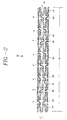
- FIGURE-2 is a side elevation of the stent 10 in a scale CAD drawing of the same stent 10 depicted in isometric view of Figure-1.
- This CAD diagram illustrates the details of the expansion struts 42, the connecting struts 44 and the stent cells 36. Counting from left to right, the connecting struts 44 in the first (1), the fourth (4) and the eighth (8) inter-expansion-strut spaces are arranged in a symmetrical pattern in the longitudinal plane of the stent 10.
- the closely paired proximal portions 68 of the two adjacent connector struts 44 have their proximal stems 66 pointing away from each other as the proximal stems 66 join to their respective attachment sites at the sides of distal ends of the expansion strut 42 pairs on the left; and the distal stems 70 of the distal portions 72 of the two paired connecting struts 44 are widely separated with their distal stems 70 pointing toward each other as the distal stems 70 join to their respective attachment sites at the sides of proximal ends of the expansion strut 42 pairs on the right.
- the proximal stem 66 of a third connecting strut 44 is widely separated pointing its proximal stem 66 toward the adjacent closely paired proximal stems 66; while the distal stem 70 of the distal portion 72 of a third connector strut 44 is now closely paired with the distal stem of adjacent connector 44 pointing their distal stems 70 pointing way from each other as their distal stems 70 join to their respective coupling site on the sides of proximal ends of the expansion strut 42 pair on the right.
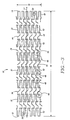
- FIGURE-3 illustrates an unexpanded tubular stent 10 of present invention in this 2-dimensional cut open drawing.
- the stent 10 is a 3-dimensional tubular structure in reality similar to the stent 10 illustrated in Figures-1 & 2, but 2-dimensional drawings are extensively used to easily illustrate the key structural and design features of the stent 10.
- the proximal end 12 of the stent 10 is on the left side and the distal end 14 is on the right.
- the cut-open stent 10 is laid out with the length 16 and longitudinal axis 17 of the stent 10 horizontally aligned.
- the circumference 18 of the stent 10 is on a vertical plane.
- Both the first and last expansion columns have their respective marker buttons 28 and 30 in their columns.
- the marker buttons 28 and 30 can be filled with a high density metal, such as gold, for a radiopaque marking.
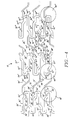
- FIGURE-4 is a magnified view of Figure-3 to add more detailed markers to the figure.
- An individual expansion strut 42 in an expansion strut pair in an expansion column 32 is aligned horizontally so that a longitudinal axis 58 of an expansion strut 42 of an expansion strut pair in an expansion column 32 would parallel to the longitudinal axis 17 of a tubular stent 10.
- a first expansion column 32' of stent 10 is made of a plurality of two adjacent companion expansion struts 42' of horizontal alignment and a joining strut 46' to form a closed loop slot 48' at a proximal or distal end of an expansion strut 42' pair.
- a joining strut 46' forms a first comer 54' where the joining strut 46' joins a first expansion strut 42' and a second comer 56' is formed where the joining strut 46' joins a second expansion strut 42' of a first expansion strut 42' pair.
- a proximal cell slot 38' or a distal cell slot 40' is formed inside a closed loop 48' of an expansion strut 42' pair in a first expansion column 32'.
- An expansion strut 42' in a first expansion column 32' is aligned horizontally, generally paralleling to the longitudinal axis 17 of the stent 10. Also first and second adjacent expansion struts 42' in a first expansion column 32' are aligned horizontally so that first and second expansion strut 42' would parallel to each other. However, one of the two expansion strut 42' in an expansion strut 42' pair in a first expansion column 32' may not parallel to the longitudinal axis 17 of the stent 10 or to the adjacent companion expansion strut 42'.
- An expansion strut 42' pair in a first expansion column 32' has a stepped-down parallel notch 50' outside on a distal or proximal end of an expansion strut 42' pair near the closed loop 48' and apart from a joining strut 46'.
- a stepped-down parallel notch 50' is created to make it an attachment site an end of diagonal connector 44' in a contralateral position from the attachment position of the other end of the same connector 44'.
- a longitudinal axis 60' of a stepped-down parallel notch 50' or a stepped-up parallel notch 52'' parallels to a longitudinal axis 58' of an expansion strut 42'.
- a first expansion column 32' has twelve (12) closed loop 48' expansion strut 42' pairs in an unbroken fashion around the circumference 18 of the stent 10. Out of twelve (12) expansion strut 42' pairs, six (6) of them have their closed loop 48' pointed proximally and the other six (6) have their closed loops 48' pointed distally in an alternating sequence. Therefor, each expansion strut 42' is connected to a closed loop 48' on each end. One closed loop 48' on one end of an expansion strut 42' points distally and other closed loop 48' on the other end points proximally.
- All the comers or angled areas in a first expansion column 32' has their respective radius of curvature to minimize sharp comers as follows: a radius of curvature at a first comer 54', a radius of curvature at a second corner 56', a radius of curvature at a inner side of first comer 54', a radius of curvature at a inner side of second comer 56', a radius of curvature 92' at an outer edge of a stepped-parallel notch and a radius of curvature 84' at a inner edge of a stepped-parallel notch.
- a second expansion column 32" of stent 10 is made of a plurality of two adjacent companion expansion struts 42" and a joining strut 46" to form a proximal or distal end of an expansion strut 42" pair to form a closed loop slots 38" or 40" .
- a joining strut 46" forms a first corner 54" where the joining strut 46" joins a first expansion strut 42" and a second comer 56 where the joining strut 46" joins a second expansion strut 42" in a second expansion column 32".
- a closed loop 48' of an expansion strut 42' pair in a second expansion column 32" form a proximal cell slot 38" or a distal cell slot 40" inside a closed loop 48" of an expansion strut 42' pair.
- An expansion strut 42" in a second expansion column 32" is aligned horizontally to generally parallel to the longitudinal axis 17 of the stent 10. Also first and second adjacent companion expansion strut 42" in a second expansion column 32" are aligned horizontally so that first and second expansion strut 42" may parallel to each other.
- one of the two expansion struts 42" in an expansion strut 42" pair in a second expansion column 32" may not parallel to the longitudinal axis 17 of the stent 10 or may not parallel to its companion expansion strut 42".
- An expansion strut 42" pair in a second expansion column 32" has a stepped-up parallel notch 52" outside on a proximal or distal end of an expansion strut 42" pair near the closed loop 48" and apart from joining strut 46".
- a stepped-up parallel notch 52'' is created to accommodate attachment of a distal stem 70' of a first connecting strut 44' in a contralateral position in relation to the attachment position of a proximal stem 66' of the same connecting strut 44'.
- a longitudinal axis 60" of a stepped-up parallel notch 52" of a second expansion strut 42" parallels to a longitudinal axis 58" of an expansion strut 42".
- a second expansion column 32" has twelve (12) closed loops 48" of expansion strut 42' pairs in an unbroken fashion around the circumference 18 of the stent 10.
- twelve (12) expansion strut 42" pairs six (6) of them have their closed loop 48" pointed distally and the other six (6) closed loops 48" pointed proximally in an alternating sequence.
- each expansion strut 42" is connected to a closed loop 48" on each end of an expansion strut 42".
- One closed loop 48" is connected to the proximal end and other closed loop 48" to the distal end.
- All the corners or angled areas in a second expansion column 32" have a radius of curvatures to minimize sharp edges in their respective sharp angled or corner areas as follows: a radius of curvature at a first comer 54", a radius of curvature at a second corner 56", a radius of curvature at a inner side of first corner 54", a radius of curvature at a inner side of second comer 56", a radius of curvature 92" at an outer edge of a stepped-parallel notch and a radius of curvature 84" at a inner edge of a stepped-parallel notch.
- a first connecting column 34' is formed of a plurality of first connecting strut 44'.
- Each connecting strut 44' in a first connecting strut column 34' includes a connecting strut proximal section with a proximal stem 66', a connecting strut distal section with a distal stem 70' and a connecting strut intermediate section 74'.
- a first connecting strut proximal section has two parts: a short stem 66' and a long portion 68'.
- a first connecting strut proximal section proximal end 62' of the short stem 66' is coupled at a perpendicular or slant angle to the contralateral outside of the distal parallel stepped notch 50' in the distal end of a first expansion strut 42' of a first expansion strut pair of a first expansion column 32'.
- a first connecting strut proximal section long portion 68' is coupled to the short stem 66' proximally at a junction 80' and to the intermediate section 74' distally at a junction 76'.
- the proximal long part 68' generally parallels to the longitudinal axis 58' of a first expansion strut 42' of a first expansion strut 42' pair in a first expansion column 32'. However, the proximal long part 68' can be made not to parallel to the longitudinal axis 58' of a first expansion strut 42"of first expansion strut 42' pair in a first expansion column 32'.
- a first connecting strut distal section also has two parts: a short stem stem 70' and a long part 72'.
- a first connecting strut distal end 64' of distal section short stem 70' is coupled at a perpendicular or slant angle to the contralateral out side of the proximal stepped parallel notch 52' in a proximal end of a second expansion strut 42" of a first expansion strut 42" pair in a second expansion column 32".
- a distal long portion 72' is coupled to the short stem 70' distally at a junction 82' at a generally perpendicular or a slant angle and to the intermediate section 74' proximally at a junction 78'.
- the distal long part 72' generally parallels to the longitudinal axis 58" of a second expansion strut 42" of a first expansion strut 42" pair in a second expansion column 32''. However, the distal long part 72' can be made not to parallel to the longitudinal axis 58" of a second expansion strut 42" of a first expansion strut 42" pair in a second expansion column 32".
- a first connecting strut proximal section including the proximal stem 66', a junction 80', the long portion 68' and a first connecting strut distal section including the distal stem 70', a junction 82', the long portion 72' are mirror images to each other, as they are on the opposite ends of a diagonally aligned intermediate section 74' of a first connecting strut 44'.
- the proximal end 62' of the proximal short stem 66' and distal end 64' of the distal short stem 70' of a first connecting strut 44' points to opposite or different directions.
- the intermediate section 74' of a first connecting strut 44' traverses diagonally through the inter-connecting space separating the first closed expansion strut loop 48' in a first expansion strut column 32' and the first closed expansion strut loop 48" in a second expansion strut column 32".
- a proximal end 62' of a proximal short stem 68' of a first connecting strut 44' in a connecting strut column 34' is attached to an outer edge on the side of a stepped-down parallel notch 50' of a first expansion strut pair closed loop 48' and a distal end 64' of a distal short stem 70' of the first connecting strut 44' in a first connecting strut column 34' is contralaterally (compared to the proximal end 62' position) attached to an outer edge on the side of a stepped-up parallel notch 52" of a first expansion strut pair loop 48" in a second expansion column 32".
- a diagonally configured first connecting strut 44' has a proximal end 62' to the contra laterally located attachment sites 50' on the side of a distal stepped-down parallel notch of a first expansion strut 42' in a first expansion column 32' and a distal end 64' to the contralaterally located attachment site 52" on the side of a proximal stepped-up parallel notch of a first expansion strut 42" in a second expansion column 32".
- An intermediate section 74' of a first connecting strut 44' in a first connecting strut column 34' is configured in a diagonally directed shape so that the proximal end 62' of the proximal stem 66' and the distal end 64' of the distal stem 70' of the connecting strut 44' would point to opposite directions to make optimum connections to the contralaterally located two coupling sites 50' and 52".
- the short proximal stem 66' is coupled at a perpendicular or slant angle to the proximal portion 68' of a first connecting strut 44' and to the distally located stepped-down parallel notch 50' of a first expansion strut 42' in a first expansion column 32'.
- short distal stem 70' is coupled at a perpendicular or slant angle to the distal portion 72' of a first connecting strut 44' and to the proximally located stepped-down parallel notch 50" of a first expansion strut 42" in a second expansion column 32'
- This perpendicular or slant angle configuration of the proximal stem 66' or distal stem 70' of the first connecting strut 44' coupling to their respective contralaterally located attachment site 50' and attachment site 52" is designed to maximally enhance the longitudinal flexibility of the first connecting strut 44' between the first expansion column 32' and the second expansion column 32''.
- the diagonally shaped connecting strut 44' is also designed to minimize the foreshortening of stent 10 when the stent 0 is expanded.
- a third expansion column 32''' of stent 10 is made of a plurality of two adjacent companion expansion struts 42''' of horizontal alignment and a joining strut 46''' to form a closed loop slot 48''' at a proximal or distal end of an expansion strut 42''' pair.
- a joining strut 46''' forms a first corner 54''' where the joining strut 46''' joins a first expansion strut 42''' and a second corner 56''' is formed where the joining strut 46''' joins a second expansion strut 42''' of a third expansion strut 42''' pair.
- a proximal cell slot 38''' or a distal cell slot 40''' is formed inside a closed loop 48' of an expansion strut 42''' pair in a third expansion column 32'''.
- An expansion strut 42''' in a third expansion column 32''' is aligned horizontally, generally paralleling to the longitudinal axis 17 of the stent 10.
- first and second adjacent expansion struts 42''' in a third expansion column 32''' are aligned horizontally so that first and second expansion strut 42''' would parallel to each other.
- one of the two expansion strut 42''' in an expansion strut 42''' pair in a third expansion column 32''' may not parallel to the longitudinal axis 17 of the stent 10 or to the adjacent companion expansion strut 42'''.
- An expansion strut 42''' pair in a third expansion column 32''' has a stepped-down parallel notch 50''' outside on a distal or proximal end of an expansion strut 42''' pair near the closed loop 48''' and apart from a joining strut 46"'.
- a proximal or distal parallel stepped-down parallel notch 50''' is created to contralaterally attach a proximal 62 or distal end 64 of a diagonal connector 44 that connects to a third expansion column 32"'.
- a longitudinal axis 60''' of a parallel stepped-down notch 50''' parallels to a longitudinal axis 58''' of an expansion strut 42"'.
- a third expansion column 32''' has twelve (12) closed loop 48''' expansion strut pairs in an unbroken fashion around the circumference 18 of the stent 10.
- each expansion strut 42' is connected to a closed loop 48''' on both ends.
- One closed loop 48''' on one end of an expansion strut 42''' points distally and other closed loop 48''' on the other end points proximally.
- each expansion strut pair cycle consists of one closed loop 48''' on the proximal and one closed loop 48''' on the distal end. All the corners or angled areas in a third expansion column 32''' has their respective radius of curvature to minimize sharp comers as follows: a radius of curvature at a first corner 54''', a radius of curvature at a second corner 56''', a radius of curvature at a inner side of first comer 54''', a radius of curvature at a inner side of second corner 56'', a radius of curvature 92''' at an outer edge of a stepped-down parallel notch 50''' and a radius of curvature 84''' at an inner edge of a stepped-down parallel notch 50'''.
- a second connecting column 34" is formed of a plurality of second connecting strut 44".
- a connecting strut 44" in a second connecting strut column 34" is a mirror image of a connecting strut 44' in a first connecting strut column 34'.
- Each connecting strut 44" in a second connecting strut column 34" includes a connecting strut proximal section, a connecting strut distal section and a connecting strut intermediate section 74'.
- a first connecting strut proximal section has two parts: a short stem 66" and a long portion 68".
- a proximal end 62" of proximal stem 66" is coupled at a perpendicular or slant angle to the contralateral out side of the distal stepped-up parallel notch 52" of a distal end of a second expansion strut 42" of a first expansion strut pair closed loop 48" of a second expansion column32".
- a first connecting strut 44" proximal section portion 68" is coupled to the proximal stem 66" proximally in a junction 80" at a generally perpendicular or a slant angle, and a first connecting strut 44" proximal portion 68" is coupled to the intermediate section 74" distally in a junction 76" at a generally perpendicular or a slant angle.
- the proximal portion 68" generally parallels to the longitudinal axis 58" of a second expansion strut 42" of a second expansion column 32".
- proximal portion 68" of a first connecting strut 44" can be made not to parallel to the longitudinal axis 58" of a second expansion strut 42"of a second expansion column 32".
- a first connecting strut 44" distal section also has two parts: a short distal stem 70" and a long portion 72".
- a first connecting strut 44" distal end 64" of distal stem 70" is coupled at a perpendicular or slant angle to the contralateral out side of the proximal stepped-down parallel notch 50''' in a proximal end of a first expansion strut 42''' of a third expansion column 32'''.
- a distal long portion 72" is coupled to the distal stem 70" distally in a junction 82" at a generally perpendicular or a slant angle, and is coupled to the intermediate section 74" proximally in a junction 78" at a generally perpendicular or a slant angle.
- the distal long portion 72" generally parallels to the longitudinal axis 58''' of a first expansion strut 42''' of a third expansion column 32'''.
- first connecting strut proximal section 66", 80", 68" and a first connecting strut distal section 70", 82'', 72'' are mirror images to each other on the opposite ends of a diagonally aligned intermediate section 74".
- the proximal end 62" and distal end 64" of a first connecting strut 44" points to opposite or different directions.
- a first connecting strut 44" intermediate section 74" proximal end is coupled at a slant angle in a junction 76" to the distal end of first connecting strut 44" proximal long portion 68" and a first connecting strut 44" intermediate section 74" distal end is coupled at a slant angle in a junction 78" to the proximal end of a first connecting strut 44" distal long portion 72".
- the intermediate section 74" of a first connecting strut 44" diagonally traverses through the inter-connecting space separating the first closed loop 46" in a second expansion strut column 32" and the first closed loop 46''' in a third expansion column 32'''.
- a proximal end 62" of a connecting strut 44" in a second connecting strut column 34" is attached to a step-up parallel notch 52" on the distal contralateral side of a second expansion strut 42" in a second expansion column 32" and a distal end 64" of a second connecting strut 44" is attached to a step-down parallel notch 50''' on the proximal contralateral side of a first expansion strut 42''' in a third expansion column 32'''.
- a diagonally arranged positions of a proximal end 62" and a distal end 64" of a first connecting strut 44" in a second connecting strut column 34" connects the two contralerally located attachment sites on the outer-edge of a respective expansion strut 42" of a second expansion columns 32" and of a respective expansion strut 42''' of a third expansion column 32'''.
- a connecting strut 44" in a second connecting strut column 34'' is configured in a diagonal shape so that each end 62" and 64" would connect the two apposed and contralaterally located attachment sites 50'' and 52''' in a two adjacent expansion columns 32" and 32''' respectively.
- the short proximal stems 66" and 70" of a connecting strut 44'' in a second connecting strut column 34" has a perpendicular or slant angle to the long proximal part 68'' and the long distal portion 72'', and to the sides of the attached sites in the respective expansion struts 42" and 42"'.
- Figure-3 is used to illustrate the serial connecting pattern of a first expansion column 32' to a second expansion column 32" by a first connecting strut column 34': of a second expansion column 32" to a third expansion column 32''' by a second connecting strut column 34". and so forth in a repeated sequence to make a prescribed length of a tubular stent 10 of present invention by adding expansion columns 32 using connecting strut columns 34.
- a first and second expansion struts 42' in a first expansion strut 42' pair are joined by a first joining strut 46' to form a closed strut pair loop 48' at a distal end of a first expansion strut 42' pair.
- a second expansion strut pair includes a third expansion strut 42' adjacent to a second expansion strut 42' and a second joining strut 48' to form a second closed loop 48' at a proximal end of a second expansion strut pair.
- a third expansion strut pair includes a fourth expansion strut 42' adjacent to a third expansion strut 42' and a third joining strut 46' to form a third closed loop 48' at a distal end of a third expansion strut 42' pair.
- a fourth expansion strut pair includes a fifth expansion strut 42' adjacent to a fourth expansion strut 42' and a fourth joining strut 46' to form a fourth closed loop 48' at a proximal end of a fourth expansion strut 42' pair.
- This first expansion column 32' building process is continued in a patterned sequence to complete a desired number expansion strut 42' pairs and closed loops 48' in a first expansion column 32'.
- a first expansion column 32' includes a twelve (12) expansion strut 42' pairs and a twelve (12) closed loops 48' in a patterned sequence.
- a number of closed loops 48'and expansion strut 42' pairs can be changed to more or less number according to the prescribed requirements of a tubular stent made for clinical use. This variation of setting a varying number of closed loops 48' and expansion strut 42' pairs in a stent 10 is within the scope of a tubular stent of present invention.
- Each of the closed loop 48' expansion strut 42' pair in a first expansion column 32' has a stepped-down parallel notch 50' for a contralateral attachment of an end of a diagonal connector strut 44', either at a distal or a proximal end of an expansion strut 42' pair.
- a first stepped-down parallel notch 50' in a first expansion column 32' is formed at a distal end of a first closed loop 48' expansion strut pair.
- a second stepped-down parallel notch 50' in a first expansion column 32' is formed at a proximal end of a second closed loop 48' expansion strut pair.
- a third step-down parallel notch 50' in a first expansion column 32' is formed at a distal end of a third closed loop 48' expansion strut pair.
- a fourth stepped-down parallel notch 50' in a first expansion column 32' is formed at a proximal end of a fourth closed loop 48' expansion strut 42' pair.
- This stepped-down parallel notch 50' building process is continued in a patterned sequence to complete a desired number of step-down parallel notches 50' in a first expansion column 32'.
- a first expansion column 32' includes a twelve (12) stepped-down parallel notches 50'.
- a stepped-down parallel notch 50' in a first expansion strut 42' is a short horizontal segment with an outer side adjacent to a first closed loop 48'.
- the longitudinal axis 60' of a stepped-down parallel notch 50' is parallel to the longitudinal axis 58' of the proximal portion of the first expansion strut 42' in a first expansion column 32'.
- All the stepped-down parallel notches 50' in a first expansion column 32' generally parallels to the longitudinal axes 58' of the respective expansion struts 42'; although a stepped-down parallel notch 50' does not have to parallel to the longitudinal axis 58' of a respective expansion struts 42'.
- a first and second expansion struts 42" in a first expansion strut pair are joined by a first joining strut 46" to form a closed strut loop 48" at a proximal end of a first expansion strut 42" pair.
- a second expansion strut pair includes a third expansion strut 42" adjacent to a second expansion strut 42" and a second joining strut 46" to form a second closed strut loop 48' at a distal end of a second expansion strut pair.
- a third expansion strut pair includes a fourth expansion strut 42" adjacent to a third expansion strut 42" and a third joining strut 46" to form a third closed strut loop 48" at a proximal end of a third expansion strut 42" pair.
- a fourth expansion strut pair includes a fifth expansion strut 42" adjacent to a fourth expansion strut 42" and a fourth joining strut 46" to form a fourth closed strut loop 48" at a distal end of a fourth expansion strut 42" pair.
- This second expansion column 32" building process is continued in a pacterned sequence to complete a desired number expansion strut 42" pairs and closed strut loops 48" in a second expansion column 32".
- a first expansion column 32" includes a twelve (12) expansion strut 42" pairs and a twelve (12) closed strut loops 48" in a patterned sequence.
- a number of closed loops 48" and expansion strut 42" pairs can be changed to more or less number according to the prescribed requirements of a tubular stent made for clinical use. This variation of setting a varying number of closed loops 48" and expansion strut 42" pairs in a stent 10 is within the scope of a tubular stent of present invention.
- Each of the closed loop 48" and expansion strut 42" pair in a second expansion column 32" has a stepped-up parallel notch 52" for a contralateral attachment of an end of a diagonal connector strut 44", either at a distal or a proximal end of an expansion strut 42" pair.
- a first stepped-up parallel notch 52" in a second expansion column 32" is formed at a distal end of a first expansion strut closed loop 48".
- a second stepped-up parallel notch 52" in a first expansion column 32' is formed at a proximal end of a second closed loop 48" expansion strut pair.
- a third step-up parallel notch 52" in a first expansion column 32' is formed at a distal end of a third closed loop 48" expansion strut pair.
- a fourth stepped-up parallel notch 52" in a first expansion column 32' is formed at a proximal end of a fourth closed loop 48" expansion strut 42" pair.
- This stepped-up parallel notch 52" building process is continued in a patterned sequence to complete a desired number of step-up parallel notches 52" in a first expansion column 32'.
- a second expansion column 32'' includes a twelve (12) stepped-up parallel notches 52".
- a stepped-up parallel notch 52" in a second expansion strut 42" is a short horizontal segment with an outer side or edge, adjacent to a first closed loop 48".
- the longitudinal axis 60" of a stepped-up parallel notch 52" is parallel to the longitudinal axis 58', of the proximal portion of same expansion strut 42" in a first expansion column 32'.
- All the stepped-up parallel notches 52" in a second expansion column 32" generally parallels to the longitudinal axes 58" of the respective expansion struts 42"; although a stepped-up parallel notch 52" does not have to parallel to the longitudinal axes 58" of a respective expansion struts 42''.
- a first and second expansion struts 42'''' in a first expansion strut 42''' pair are joined by a first joining strut 46' to form a closed strut pair loop 48''' at a proximal end of a first expansion strut 42''' pair.
- a second expansion strut pair includes a third expansion strut 42''' adjacent to a second expansion strut 42''' and a second joining strut 46''' to form a second closed loop 48''' at a distal end of a second expansion strut pair.
- a third expansion strut pair includes a fourth expansion strut 42''' adjacent to a third expansion strut 42''' and a third joining strut 46''' to form a third closed loop 48''' at a proximal end of a third expansion strut 42''' pair.
- a fourth expansion strut pair includes a fifth expansion strut 42''' adjacent to a fourth expansion strut 42''' and a fourth joining strut 46''' to form a fourth closed loop 48' at a distal end of a fourth expansion strut 42''' pair.
- This third expansion column 32''' building process is continued in a patterned sequence to complete a desired number expansion strut 42''' pairs and closed loops 48'''' in a third expansion column 32'''.
- a third expansion column 32''' includes a twelve (12) expansion strut 42''' pairs and a twelve (12) closed loops 48''' in a patterned sequence.
- a number of closed loops 48''' and expansion strut 42''' pairs can be changed to more or less number according to the prescribed requirements of a tubular stent made for clinical use. This variation of setting a varying number of closed loops 48''' and expansion strut 42''' pairs in a stent 10 is within the scope of a tubular stent of present invention.
- Each of the closed loop 48''' expansion strut 42''' pair in a third expansion column 32''' has a stepped-down parallel notch 50''' for a contralateral attachment of an end of a diagonal connector strut 44, either at a distal or a proximal end of an expansion strut 42 pair.
- a first stepped-down parallel notch 50' in a third expansion column 32''' is formed at a proximal end of a first closed loop 48''' expansion strut pair.
- a second stepped-down parallel notch 50''' in a third expansion column 32''' is formed at a distal end of a second closed loop 48''' expansion strut pair.
- a third step-down parallel notch 50''' in a third expansion column 32''' is formed at a proximal end of a third closed loop 48''' expansion strut pair.
- a fourth stepped-down parallel notch 50''' in a third expansion column 32''' is formed at a distal end of a fourth closed loop 48''' expansion strut 42''' pair.
- This stepped-down parallel notch 50''' building process is continued in a patterned sequence to complete a desired number of step-down parallel notches 50'''' in a third expansion column 32"'.
- a third expansion column 32''' includes a twelve (12) stepped-down parallel notches 50'''.
- a stepped-down parallel notch 50''' in a first expansion strut 42''' pair is a short horizontal segment with an outer side adjacent to a first closed loop 48'''.
- the longitudinal axis 60' of a stepped-down parallel notch 50''' is parallel to the longitudinal axis 58''' of the distal long portion of the first expansion strut 42''' in a third expansion column 32'''.
- All the stepped-down parallel notches 50''' in a third expansion column 32''' generally parallels to the longitudinal axes 58''' of the respective expansion struts 42'''; although a stepped-down parallel notch 50''' does not have to parallel to the longitudinal axis 58''' of a respective expansion struts 42'''.
- first connecting struts 44' in a first connecting strut column 34', with the first connecting strut 44' at the top and the sixth connecting strut 44' at the bottom of the first connecting strut column 34' in Figure 3.
- the first connecting column 34' connects the first expansion column 32' and the second expansion strut 42' column 32" in an unbroken fashion to form a tubular sub-unit with a longitudinal axis 17 of a tubular stent 10 of present invention.
- six (6) closed stent cells 36' are formed.
- Each of these stent cells 36' is completely closed by a combination of expansion struts 42' and joining struts 46' in a first expansion column 32', the expansion struts 42" and joining struts 46" in a second expansion column 32" and two connecting strut 44' in a first connecting strut column 34'.
- a stent cell 36' in a stent 10 has one cell slot 38' in the proximal end and one cell slot 40" in the distal end.
- a proximal cell slot 38' is located in juxtaposition with an adjacent distal cell slot 40'.
- a distal cell slot 40" is located in juxtaposition with an adjacent proximal cell slot 38".
- a closed stent cell formed between the first 32' and second 32" expansion columns with a first connecting column 34' has an asymmetrical cell geometry in this unexpanded stent pattern.
- the second connecting column 34" also has six connecting struts 44" in a second connecting strut column 34", with the first connecting strut 44" at the top and the sixth connecting strut 44" at the bottom of a second connecting strut column 34" in Figure 3.
- the second connecting column 34" couples the second expansion column 32" to the third expansion column 32''' in an unbroken fashion to form a tubular sub-unit with a longitudinal axis 17 in a tubular stent 10 of present invention.
- six (6) closed stent cells 36" are formed.
- Each of these stent cells 36" is completely closed by a combination of expansion struts 42" and joining struts 46" in a second expansion column 32".
- a stent cell 36" in a stent 10 has one cell slot 38" in the proximal end and one cell slot 40''' in the distal end.
- a proximal cell slot 38" is located in juxtaposition with an adjacent distal cell slot 40".
- a distal cell slot 40''' is located in juxtaposition with an adjacent proximal cell slot 38'''.
- a closed stent cell formed between the second 32" and third 32''' expansion columns and a second connecting column 34" has an asymmetrical cell geometry in this unexpanded stent pattern.
- FIGURE-4a illustrates how the proximal and distal ends of a connecting strut 44 couples to the sides of the respective expansion struts 42'.
- a first connecting strut 44' is drawn in dotted line to better illustrate how proximal stem 66' and distal stem 70' are coupled to the sides of their respective struts 42', 42".
- the axis 67' of proximal stem 66' of a first connecting strut 44' and the axis 60' of the distal stepped-down parallel notch 50' form an angle A' nearest to the stepped transition.
- An angle A' is preferably 90 degrees or greater but can be less than 90 degrees.
- the axis of outer edge 45' of the stepped-down parallel notch 50' parallels to the axis 60' of the same segment 50'.
- the joining angle A' between the axis 67' and axis 60' is generally similar to the joining angle A' between the axis 67' and the plane of the outer edge 45' of the stepped parallel notch 50'. Similar relationship is repeated in the distal stem 70' of a first connecting strut 44'.
- the axis 71' of distal stem 70' of a first connecting strut 44' and the axis 60" of the a stepped-up parallel notch 52" form an angle B' nearest to the stepped transition.
- An angle B' is preferably 90 degrees or greater but can be less than 90 degrees.
- the axis of outer edge 45" of the stepped-up parallel notch 52" parallels to the axis 60" of the same segment 52".
- the joining angle B' between the axis 71' and axis 60" is generally similar to the joining angle B' between the axis 71' and the plane of the outer edge 45" of the stepped parallel notch 52".
- a proximal stem 67' clearly joins to the outer edge 45'on the side of a stepped parallel notch 50' with an axis 60' of a first expansion strut 42' in a first expansion column 32'.
- the distal stem 70' clearly joins to the outer edge 45" of the stepped parallel notch 52" with an axis 60" of a first expansion strut 42" in a second expansion column 32".
- a second connecting strut 44" is drawn in dotted line to better illustrate how proximal stem 66" and distal stem 70" are coupled to the sides of their respective struts 42", 42'''.
- the axis 67" of proximal stem 66" of a second connecting strut 44" and the axis 60" of the distal stepped-up parallel notch 52" form an angle A" nearest to the stepped transition.
- An angle A" is preferably 90 degrees or greater but can be less than 90 degrees.
- the axis of outer edge 45" of the stepped-up parallel notch 52" parallels to the axis 60" of the same segment 52".
- the joining angle A'' between the axis 67" and axis 60" is generally similar to the joining angle A'' between the axis 67' and the plane of the outer edge 45' of the same stepped parallel notch 52". Similar relationship is repeated in the distal stem 70" of a second connecting strut 44".
- the axis 71" of distal stem 70" of a second connecting strut 44" and the axis 60" of the a stepped-up parallel notch 52" form an angle B" nearest to the stepped transition.
- An angle B" is preferably 90 degrees or greater but can be less than 90 degrees.
- the axis of outer edge 45" of the stepped-up parallel notch 52" parallels to the axis 60" of the same segment 52".
- the joining angle B" between the axis 71' and axis 60" is generally similar to the joining angle B" between the axis 71' and the plane of the outer edge 45" of the stepped parallel notch 52".
- a proximal stem 67" clearly joins to the outer edge 45'' on the side of a stepped parallel notch 52" with an axis 60" of a first expansion strut 42" in a second expansion column 32".
- the distal stem 70" clearly joins to the outer edge 45" of the stepped parallel notch 52''' with an axis 60''' of a first expansion strut 42''' in a third expansion column 32'''.
- FIGURE-4b illustrates an alternative coupling of the proximal stem 66 and distal stem 70 of a connecting strut 44 to the contralateral outer side of the opposing expansion strut closed loops 48 in two adjacent expansion columns 32.
- a proximal stem 66' of a first connecting strut 44' in a first connecting column 34' is attached to the outer side 43' of the distal long portion with longitudinal axis 58' of a first expansion strut 42' of a first expansion strut pair in a first expansion column 32'.
- This attachment configuration is drastically different from the examples discussed in Figures 4 and 4a.
- the proximal stem 66' is attached to a contralateral outside edge 43' on a distal end of a first expansion strut 42' opposite from a distal stepped-up parallel notch 52' of a first expansion strut pair closed loop 48'.
- a distal stem 70' of a first connecting strut 44' in a first connecting column 34' is attached to the outer side 43" of the proximal long portion with longitudinal axis 58" of a second expansion strut 42" of a first expansion strut pair in a second expansion column 32".
- This attachment configuration of the distal stem 70' to the distal long portion of a first expansion strut 42"in a second expansion column 32" is different from the examples discussed in Figures 4 and 4a.
- the distal stem 70' is attached to a contralateral outside edge 43" on a distal end of a second expansion strut 42'' opposite from a proximal stepped-down parallel notch 52" of a first expansion strut pair closed loop 48".
- a proximal stem 66" of a first connecting strut 44" in a second connecting column 34" is attached to the outer side 43" of the distal long portion with longitudinal axis 58" of a second expansion strut 42" of a first expansion strut pair in a second expansion column 32''.
- This attachment configuration is distinctly different from the examples discussed in Figures 4 and 4a.
- the proximal stem 66" is attached to a contralateral outside edge 43" on a distal end of a second expansion strut 42" opposite from a distal stepped-down parallel notch 50" of a first expansion strut pair closed loop 48".
- a distal stem 70" of a second connecting strut 44" in a second connecting column 34" is attached to the outer side 43''' of the proximal long portion with longitudinal axis 58" of a first expansion strut 42''' of a first expansion strut pair in a third expansion column 32"'.
- This attachment configuration of the distal stem 70" to the distal long portion of a first expansion strut 42''' in a third expansion colunm 32''' is different from the examples discussed in Figures 4 and 4a.
- the distal stem 70' is attached to a contralateral outside edge 43''' on a proximal end of a first expansion strut 42''' opposite from a proximal stepped-down parallel notch 52" of a first expansion strut pair closed loop 48".
- These alternative connector attachment configurations are within the scope of stent 10 of present invention.
- expansion strut 42 pairs and closed expansion loops 48 in a first 32', second 32" and third 32''' expansion columns of the alternative design depicted in Figure-4b are exactly same as the specifications detailed in Figures 3,4 and 4a.
- shape and attachment details of first 44'and second 44"connecting struts in a first 34'and second 34"connecting columns are also exactly same as detailed in Figures 3 and 4.
- FIG-5 illustrates examples of how skipped connector links between two adjacent expansion columns (32) can be created.
- Skipped connector pattern can be utilized when more flexibility is desired in a stent 10 made for clinical use. The more connectors are removed, the more flexible the stent 10 becomes. However, as the number of skipped connector (44) increase, the vessel-cover of a stent 10 suffers proportionally. As the number of skipped connector link increase, the axio-lateral strength of the stent also suffers increasingly.
- a connector column (A) in Figure-5 there are only two (2) consecutive connectors 44 linking the two adjacent expansion columns 32.
- a connector column (B) there are three (3) connectors 44 linking the two adjacent expansion columns 32, interpose by a skipped connector between the three connectors 44.
- a connector column (C) there is a pair of two consecutive connectors 44 separated by single unconnected link between the pair of two consecutive connectors 44.
- a connector column (D) there are two (2) connectors linking the two adjacent expansion columns 32, separated by two skipped connectors between them.
- a connector column (E) there is only one connector 44 linking the two adjacent expansion columns 32.
- stent 10 can have only one of these five (5) skippedlink pattern through out the stent 10, or combination of more than one skipped pattern in a stent 10. All five of these skipped connector 44 liking pattern are within the scope of stent 10 of present invention.
Landscapes
- Health & Medical Sciences (AREA)
- Engineering & Computer Science (AREA)
- Biomedical Technology (AREA)
- Heart & Thoracic Surgery (AREA)
- Life Sciences & Earth Sciences (AREA)
- Cardiology (AREA)
- Oral & Maxillofacial Surgery (AREA)
- Transplantation (AREA)
- Physics & Mathematics (AREA)
- Vascular Medicine (AREA)
- Optics & Photonics (AREA)
- Animal Behavior & Ethology (AREA)
- General Health & Medical Sciences (AREA)
- Public Health (AREA)
- Veterinary Medicine (AREA)
- Prostheses (AREA)
- Media Introduction/Drainage Providing Device (AREA)
Claims (36)
- Entlang dem Umfang verbundener Stent (10) in einem nicht ausgedehnten Zustand mit einer Längsachse, umfassend:wobei in der ersten Ausdehnungsspalte (32') der proximale Abschnitt der ersten Ausdehnungsstrebe eine Längsachse (58') aufweist, die parallel zu und versetzt von einer Längsachse (60') des gestuften distalen Abschnitts (50') der ersten Ausdehnungsstrebe verläuft, und in der zweite Ausdehnungsspalte (32'') der gestufte proximale Abschnitt (52'') der ersten Ausdehnungsstrebe eine Längsachse (60'') aufweist, die parallel zu und versetzt von einer Längsachse (58") des distalen Abschnitts der ersten Ausdehnungsstrebe verläuft.eine Vielzahl von ersten Paaren von Ausdehnungsstreben (42'), die eine erste Ausdehnungsspalte bilden (32'), wobei die ersten Ausdehnungsstrebenpaare eine erste Ausdehnungsstrebe, eine zweite Ausdehnungsstrebe und eine erste Verbindungsstrebe (46) umfassen, die ein distales Ende der ersten Ausdehnungsstrebe an ein distales Ende der zweiten Ausdehnungsstrebe koppelt, wobei die erste Ausdehnungsstrebe einen gestuften distalen Abschnitt (50') aufweist und eine zweite Ausdehnungsstrebe einen gestuften proximalen Abschnitt (50'') aufweist;eine Vielzahl von zweiten Paaren von Ausdehnungsstreben (42''), die eine zweite Ausdehnungsspalte (32") beschreiben, wobei die zweiten Ausdehnungsstrebenpaare eine erste Ausdehnungsstrebe, eine zweite Ausdehnungsstrebe und eine erste Verbindungsstrebe (46'') umfassen, die ein distales Ende der ersten Ausdehnungsstrebe an ein distales Ende der zweiten Ausdehnungsstrebe koppelt, wobei die erste Ausdehnungsstrebe einen gestuften proximalen Abschnitt (52'') aufweist und die zweite Ausdehnungsstrebe einen gestuften distalen Abschnitt (52") aufweist; undeine erste fortlaufende Verknüpfungsstrebenspalte (34'), gebildet aus einer Vielzahl von fortlaufenden Verknüpfungsstreben (44') und umfassend eine erste fortlaufende Verknüpfungsstrebe, wobei die erste fortlaufende Verknüpfungsstrebenspalte die erste Ausdehnungsspalte (32') an die zweite Ausdehnungsspalte (32'') koppelt,
- Stent nach Anspruch 1, wobei die erste (32') und zweite (32'') Ausdehnungsspalte und die erste fortlaufende Verknüpfungsstrebenspalte (34') asymmetrische Zellen (36') bilden.
- Stent nach Anspruch 2, wobei jede asymmetrische Zelle (36') einen proximalen Schlitz (38') umfasst, der zwischen einem Paar benachbarter Ausdehnungsstreben in der ersten Ausdehnungsspalte (32') gebildet ist, und einen distalen Schlitz (40"), der zwischen einem Paar benachbarter Ausdehnungsstreben in der zweiten Ausdehnungsspalte (32") gebildet ist.
- Stent nach Anspruch 1, wobei jede fortlaufende Verknüpfungsstrebe in der ersten fortlaufenden Verknüpfungsstrebenspalte (32') einen proximalen Abschnitt (68') aufweist, der an einen proximalen Stiel (66') gekoppelt ist, einen distalen Abschnitt (72'), der an einen distalen Stiel (70') gekoppelt ist und einen Zwischenabschnitt (74'), der die proximalen und distalen Abschnitte der fortlaufenden Verknüpfungsstrebe miteinander koppelt.
- Stent nach Anspruch 4, wobei jeder Zwischenabschnitt (74') einer fortlaufenden Verknüpfungsstrebe (44') in der ersten fortlaufenden Verknüpfungsstrebenspalte (32') die proximalen (68') und distalen (72) Abschnitte der fortlaufenden Verknüpfungsstrebe diagonal miteinander koppelt.
- Stent nach Anspruch 1, wobei die erste fortlaufende Verknüpfungsstrebe (44') den gestuften distalen Abschnitt der ersten Ausdehnungsstrebe (42') der ersten Ausdehnungsspalte (32') gegenläufig an den gestuften proximalen Abschnitt der ersten Ausdehnungsstrebe der zweiten Ausdehnungsspalte (32'') koppelt.
- Stent nach Anspruch 4, wobei der proximale Stiel (66') der ersten fortlaufenden Verknüpfungsstrebe (34') gegenläufig an den gestuften distalen Abschnitt der ersten Ausdehnungsstrebe (42') der ersten Ausdehnungsspalte (32') gekoppelt ist, und der distale Stiel (72') der ersten fortlaufenden Verknüpfungsstrebe (34') gegenläufig an den gestuften proximalen Abschnitt der ersten Ausdehnungsstrebe der zweiten Ausdehnungsspalte (32'') gekoppelt ist.
- Stent nach Anspruch 4, wobei der proximale Stiel (66') der ersten fortlaufenden Verknüpfungsstrebe (34') gegenläufig an eine Seite des gestuften distalen Abschnitts der ersten Ausdehnungsstrebe (42') der ersten Ausdehnungsspalte (32') gekoppelt ist, und der distale Stiel (72') der ersten fortlaufenden Verknüpfungsstrebe gegenläufig an eine Seite des gestuften proximalen Abschnitts der ersten Ausdehnungsstrebe der zweiten Ausdehnungsspalte (32'') gekoppelt ist.
- Stent nach einem der Ansprüche 1 bis 8, wobei die Längsachse des proximalen Abschnitts der ersten Ausdehnungsstrebe in der ersten Ausdehnungsspalte (32') parallel zur Längsachse des distalen Abschnitts der zweiten Ausdehnungsstrebe in der ersten Ausdehnungsspalte verläuft.
- Stent nach einem der Ansprüche 1 bis 9, wobei in der ersten Ausdehnungsspalte (32') eine erste Seite des proximalen Abschnitts der ersten Ausdehnungsstrebe (42') eine gleiche Längsachse wie eine erste Seite des proximalen Abschnitts der ersten fortlaufenden Verknüpfungsstrebe (44') in der ersten fortlaufenden Verknüpfungsstrebenspalte (34') aufweist.
- Stent nach Anspruch 10, wobei in der ersten Ausdehnungsspalte (32') eine zweite Seite des distalen Abschnitts der zweiten Ausdehnungsstrebe eine gleiche Längsachse wie eine zweite Seite eines distalen Abschnitts der ersten fortlaufenden Verknüpfungsstrebe (44') in der ersten fortlaufenden Verknüpfungsstrebenspalte (34') aufweist.
- Stent nach Anspruch 11, wobei in der zweiten Ausdehnungsspalte (32'') eine zweite Seite des distalen Abschnitts der ersten Ausdehnungsstrebe eine gleiche Längsachse wie die zweite Seite des distalen Abschnitts der ersten fortlaufenden Verknüpfungsstrebe (44') in der ersten fortlaufenden Verknüpfungsstrebenspalte (34') aufweist.
- Stent nach Anspruch 1, weiterhin umfassend:eine Vielzahl von Paaren dritter Ausdehnungsstreben (42'''), die eine dritte Ausdehnungsspalte (32''') bilden, wobei die dritten Ausdehnungsstrebenpaare eine erste Ausdehnungsstrebe, eine zweite Ausdehnungsstrebe und eine erste Verbindungsstrebe (46''') umfassen, die ein proximales Ende der ersten Ausdehnungsstrebe an ein proximales Ende der zweiten Ausdehnungsstrebe koppelt, wobei die erste Ausdehnungsstrebe einen gestuften proximalen Abschnitt und die zweite Ausdehnungsstrebe einen gestuften distalen Abschnitt aufweist; undeine zweite fortlaufende Verknüpfungsstrebenspalte (34"), gebildet aus einer Vielzahl von Verknüpfungsstreben (44'') und umfassend eine erste fortlaufende Verbindungsstrebe, wobei die erste fortlaufende Verknüpfungsstrebenspalte die zweite Ausdehnungsspalte (32'') an die dritte Ausdehnungsspalte koppelt.
- Stent nach Anspruch 13, wobei die ersten (32') und zweiten (32'') Ausdehnungsspalten und die erste fortlaufende Verknüpfungsstrebenspalte (34') einen ersten Satz asymmetrischer Zellen (36) bilden, und die zweiten und dritten (32''') Ausdehnungsspalten und die zweite fortlaufende Verknüpfungsstrebenspalte einen zweiten Satz asymmetrischer Zellen bilden.
- Stent nach Anspruch 14, wobei jeder erste Satz einer asymmetrischen Zelle (36) einen proximalen Zellenschlitz (38') umfasst, der zwischen einem Paar benachbarter Ausdehnungsstreben in der ersten Ausdehnungsspalte (32') gebildet ist, und einen distalen Zellenschlitz (40") umfasst, der zwischen einem Paar benachbarter Ausdehnungsstreben in der zweiten Ausdehnungsspalte (32'') gebildet ist, und jeder zweite Satz einer asymmetrischen Zelle einen proximalen Zellenschlitz (38'') umfasst, der zwischen einem Paar benachbarter Ausdehnungsstreben in der zweiten Ausdehnungsspalte gebildet ist, und einen distalen Schlitz (40''') umfasst, der zwischen einem Paar benachbarter Ausdehnungsstreben in der dritten Ausdehnungsspalte(32"') gebildet ist.
- Stent nach Anspruch 13 oder 14, wobei jede fortlaufende Verknüpfungsstrebe (44', 44'') in der ersten (34') und zweiten (34") fortlaufenden Verknüpfungsstrebenspalte einen proximalen Abschnitt (68', 68'') mit einem proximalen Stiel (66', 66'') aufweist, einen distalen Abschnitt (72', 72'') mit einem distalen Stiel (70', 70'') und einen Zwischenabschnitt (74', 74''), der die proximalen und distalen Abschnitte miteinander koppelt.
- Stent nach Anspruch 16, wobei der Zwischenabschnitt (74') jeder fortlaufenden Verknüpfungsstrebe (44') der ersten fortlaufenden Verknüpfungsstrebenspalte (34') die proximalen und distalen Abschnitte (68', 72') diagonal miteinander koppelt.
- Stent nach Anspruch 17, wobei die Zwischenabschnitte (74'') der fortlaufenden Verknüpfungsstreben (44'') der ersten fortlaufenden Verknüpfungsstrebenspalte (34') alle in dieselbe Richtung verlaufen.
- Stent nach Anspruch 18, wobei die Zwischenabschnitte (74', 74'') der fortlaufenden Verknüpfungsstreben (44'') der zweiten fortlaufenden Verknüpfungsstrebenspalte (34'') alle in dieselbe Richtung verlaufen.
- Stent nach Anspruch 19, wobei die Zwischenabschnitte (74', 74'') der fortlaufenden Verknüpfungsstreben der ersten (34') und zweiten (34'') fortlaufenden Verknüpfungsstrebenspalte in verschiedenen Richtungen verlaufen.
- Stent nach Anspruch 20, wobei nur ein Abschnitt der Ausdehnungsstreben in der ersten Ausdehnungsstrebenspalte (32') durch fortlaufende Verknüpfungsstreben in der ersten fortlaufenden Verknüpfungsstrebenspalte (34') an Ausdehnungsstreben in der zweiten Ausdehnungsstrebenspalte (32'') gekoppelt ist.
- Stent nach Anspruch 21, wobei nur ein Abschnitt der Ausdehnungsstreben in der zweiten Ausdehnungsstrebenspalte (32'') durch fortlaufende Verknüpfungsstreben in der zweiten fortlaufenden Verknüpfungsstrebenspalte (34'') an Ausdehnungsstreben in der dritten Ausdehnungsstrebenspalte (32''') gekoppelt ist.
- Stent nach Anspruch 19, wobei die erste fortlaufende Verknüpfungsstrebe (44') der ersten fortlaufenden Verknüpfungsstrebenspalte (34') den gestuften distalen Abschnitt der ersten Ausdehnungsstrebe der ersten Ausdehnungsspalte (32') gegenläufig an den gestuften proximalen Abschnitt der ersten Ausdehnungsstrebe der zweiten Ausdehnungsspalte (32'') koppelt, und die erste fortlaufende Verknüpfungsstrebe (44') der zweiten fortlaufenden Verknüpfungsstrebenspalte (34'') den gestuften distalen Abschnitt der zweiten Ausdehnungsstrebe der zweiten Ausdehnungsspalte (32'') gegenläufig an den gestuften proximalen Abschnitt der ersten Ausdehnungsstrebe der dritten Ausdehnungsspalte (32''') koppelt.
- Stent nach Anspruch 23, wobei der proximale Stiel (66') der ersten fortlaufenden Verknüpfungsstrebe (44') in der ersten fortlaufenden Verknüpfungsstrebenspalte (34') an eine Seite des gestuften distalen Abschnitts der ersten Ausdehnungsstrebe (42') in der ersten Ausdehnungsspalte (32') gekoppelt ist, der distale Stiel (70') der ersten fortlaufenden Verknüpfungsstrebe in der ersten fortlaufenden Verknüpfungsstrebenspalte an eine Seite des gestuften proximalen Abschnitts der ersten Ausdehnungsstrebe (42'') in der zweiten Ausdehnungsspalte (32'') gekoppelt ist, der proximale Stiel (66'') der ersten fortlaufenden Verknüpfungsstrebe in der zweiten fortlaufenden Verknüpfungsstrebenspalte (34'') an eine Seite des gestuften distalen Abschnitts der zweiten Ausdehnungsstrebe (42'') in der zweiten Ausdehnungsspalte (32'') gekoppelt ist; und der distale Stiel (70'') der ersten fortlaufenden Verknüpfungsstrebe in der zweiten fortlaufenden Verknüpfungsstrebenspalte an eine Seite des gestuften proximalen Abschnitts der ersten Ausdehnungsstrebe in der dritten Ausdehnungsspalte (32''') gekoppelt ist.
- Stent nach Anspruch 24, wobei der proximale Stiel (66') der ersten fortlaufenden Verknüpfungsstrebe (44') in der ersten fortlaufenden Verknüpfungsstrebenspalte (34') in einem Verknüpfungswinkel (A') an eine Seite des gestuften distalen Abschnitts der ersten Ausdehnungsstrebe (42') in der ersten Ausdehnungsspalte (32') gekoppelt ist, der 85° oder mehr beträgt und am nächsten einer Stufe gebildet ist, die in der ersten Ausdehnungsstrebe der ersten Ausdehnungsspalte gebildet ist, und der proximale Stiel (66'') der ersten fortlaufenden Verknüpfungsstrebe (44'') in der zweiten fortlaufenden Verknüpfungsstrebenspalte (34'') in einem Verknüpfungswinkel (A'') an die Seite des gestuften distalen Abschnitts der zweiten Ausdehnungsstrebe (42'') in der zweiten Ausdehnungsspalte (32'') gekoppelt ist, der 85° oder mehr beträgt und am nächsten einer Stufe gebildet ist, die in der zweiten Ausdehnungsstrebe der zweiten Ausdehnungsspalte gebildet ist.
- Stent nach Anspruch 25, wobei der distale Stiel (70') der ersten fortlaufenden Verknüpfungsstrebe (44') in der ersten fortlaufenden Verknüpfungsstrebenspalte (34') in einem Verknüpfungswinkel (B') an die Seite des gestuften proximalen Abschnitts der ersten Ausdehnungsstrebe (42) in der ersten Ausdehnungsspalte (32') gekoppelt ist, der 85° oder mehr beträgt und am nächsten einer Stufe gebildet ist, die in der ersten Ausdehnungsstrebe der zweiten Ausdehnungsspalte gebildet ist, und der distale Stiel (70'') der ersten fortlaufenden Verknüpfungsstrebe (44'') in der zweiten fortlaufenden Verknüpfungsstrebenspalte (34'') in einem Verknüpfungswinkel (B") an die Seite des gestuften proximalen Abschnitts der ersten Ausdehnungsstrebe (42''') in der dritten Ausdehnungsspalte (32''') gekoppelt ist, der 85° oder mehr beträgt und am nächsten einer Stufe gebildet ist, die in der ersten Ausdehnungsstrebe der dritten Ausdehnungsspalte gebildet ist.
- Stent nach Anspruch 25 oder 26, wobei jeder Verknüpfungswinkel (A', A'', B', B'') 90° oder mehr beträgt.
- Entlang dem Umfang verbundener Stent (10) in einem nicht ausgedehnten Zustand mit einer Längsachse, umfassend:wobei in der ersten Ausdehnungsspalte (32'') der distale Abschnitt der ersten Ausdehnungsstrebe eine Längsachse (60'') aufweist, die parallel zu und versetzt von einer Längsachse (58'') des proximalen Abschnitts der zweiten Ausdehnungsstrebe verläuft, und in der zweite Ausdehnungsspalte (32''') der proximale Abschnitt der ersten Ausdehnungsstrebe eine Längsachse (60''') aufweist, die parallel zu und versetzt von einer Längsachse (58''') des distalen Abschnitts der zweiten Ausdehnungsstrebe ist.eine Vielzahl von ersten Paaren von Ausdehnungsstreben (42''), die eine erste Ausdehnungsspalte (32'') bilden, wobei die ersten Ausdehnungsstrebenpaare eine erste Ausdehnungsstrebe, eine zweite Ausdehnungsstrebe und eine erste Verbindungsstrebe (46'') umfassen, die ein distales Ende der ersten Ausdehnungsstrebe an ein distales Ende der zweiten Ausdehnungsstrebe koppelt, wobei die erste Ausdehnungsstrebe einen gestuften proximalen Abschnitt (52'') aufweist und die zweite Ausdehnungsstrebe einen gestuften distalen Abschnitt (52'') aufweist;eine Vielzahl von zweiten Paaren von Ausdehnungsstreben (42'''), die eine zweite Ausdehnungsspalte (32''') beschreiben, wobei die zweiten Ausdehnungsstrebenpaare eine erste Ausdehnungsstrebe, eine zweite Ausdehnungsstrebe und eine erste Verbindungsstrebe (46''') umfassen, die ein distales Ende der ersten Ausdehnungsstrebe an ein distales Ende der zweiten Ausdehnungsstrebe koppelt, wobei die erste Ausdehnungsstrebe einen gestuften distalen Abschnitt (52''') aufweist und die zweite Ausdehnungsstrebe einen gestuften proximalen Abschnitt (52''') aufweist; undeine erste fortlaufende Verknüpfungsstrebenspalte (34''), gebildet aus einer Vielzahl von fortlaufenden Verknüpfungsstreben (44'') und umfassend eine erste fortlaufende Verknüpfungsstrebe, wobei die erste fortlaufende Verknüpfungsstrebenspalte die erste Ausdehnungsspalte (32'') an die zweite Ausdehnungsspalte (32''') koppelt,
- Stent nach Anspruch 28, wobei die erste (32") und zweite (32''') Ausdehnungsspalte und die erste fortlaufende Verknüpfungsstrebenspalte (44'') asymmetrische Zellen (36'') bilden.
- Stent nach Anspruch 29, wobei jede asymmetrische Zelle einen proximalen Schlitz (38'') umfasst, der zwischen einem Paar benachbarter Ausdehnungsstreben in der ersten Ausdehnungsspalte (32'') gebildet ist, und einen distalen Schlitz (40'''), der zwischen einem Paar benachbarter Ausdehnungsstreben in der zweiten Ausdehnungsspalte (32''') gebildet ist.
- Stent nach Anspruch 28, wobei jede fortlaufende Verknüpfungsstrebe in der ersten fortlaufenden Verknüpfungsstrebenspalte (34'') einen proximalen Abschnitt (68") mit einem proximalen Stiel (66'') aufweist, einen distalen Abschnitt (72'') mit einem distalen Stiel (70") und einen Zwischenabschnitt (74''), der die proximalen und distalen Abschnitte der fortlaufenden Verknüpfungsstrebe (44'') miteinander koppelt.
- Stent nach Anspruch 31, wobei jeder Zwischenabschnitt (74'') einer fortlaufenden Verknüpfungsstrebe (44'') in der ersten fortlaufenden Verknüpfungsstrebenspalte (34'') die proximalen (68'') und distalen (72'') Abschnitte der fortlaufenden Verknüpfungsstrebe diagonal miteinander koppelt.
- Stent nach Anspruch 32, wobei die erste fortlaufende Verknüpfungsstrebe (44'') den gestuften distalen Abschnitt der ersten Ausdehnungsstrebe (42") der ersten Ausdehnungsspalte (32'') gegenläufig an den gestuften proximalen Abschnitt der ersten Ausdehnungsstrebe der zweiten Ausdehnungsspalte (32''') koppelt.
- Stent nach Anspruch 30, wobei der proximale Stiel (66") der ersten fortlaufenden Verknüpfungsstrebe (44'') gegenläufig an den distalen Abschnitt der ersten Ausdehnungsstrebe der ersten Ausdehnungsspalte (32") gekoppelt ist, und der distale Stiel (70'') der ersten fortlaufenden Verknüpfungsstrebe gegenläufig an den proximalen Abschnitt der ersten Ausdehnungsstrebe (42''') der zweiten Ausdehnungsspalte (32''') gekoppelt ist.
- Stent nach Anspruch 31, wobei der proximale Stiel (66'') der ersten fortlaufenden Verknüpfungsstrebe (44'') gegenläufig an eine Seite des distalen Abschnitts der ersten Ausdehnungsstrebe (42'') der ersten Ausdehnungsspalte (32'') gekoppelt ist, und der distale Stiel (70'') der ersten fortlaufenden Verknüpfungsstrebe gegenläufig an eine Seite des proximalen Abschnitts der ersten Ausdehnungsstrebe (42''') der zweiten Ausdehnungsspalte (32''') gekoppelt ist.
- Stent nach einem der Ansprüche 28 bis 35, wobei der distale Abschnitt der ersten Ausdehnungsstrebe in der ersten Ausdehnungsspalte (32'') eine Längsachse aufweist, die parallel zu einer Längsachse des proximalen Abschnitts der ersten Ausdehnungsstrebe in der zweiten Ausdehnungsspalte verläuft.
Priority Applications (1)
| Application Number | Priority Date | Filing Date | Title |
|---|---|---|---|
| EP05006859A EP1557139A3 (de) | 1998-02-03 | 1999-02-02 | Aus horizontalen expandierbaren Streben und kontralateral befestigten diagonalen Verbindern versehener Stent |
Applications Claiming Priority (5)
| Application Number | Priority Date | Filing Date | Title |
|---|---|---|---|
| US7352398P | 1998-02-03 | 1998-02-03 | |
| US73523P | 1998-02-03 | ||
| US241320 | 1999-02-01 | ||
| US09/241,320 US6113627A (en) | 1998-02-03 | 1999-02-01 | Tubular stent consists of horizontal expansion struts and contralaterally attached diagonal-connectors |
| PCT/US1999/002171 WO1999038457A1 (en) | 1998-02-03 | 1999-02-02 | Tubular stent consisting of horizontal expansion struts and contralaterally attached diagonal-connectors |
Related Child Applications (1)
| Application Number | Title | Priority Date | Filing Date |
|---|---|---|---|
| EP05006859A Division EP1557139A3 (de) | 1998-02-03 | 1999-02-02 | Aus horizontalen expandierbaren Streben und kontralateral befestigten diagonalen Verbindern versehener Stent |
Publications (2)
| Publication Number | Publication Date |
|---|---|
| EP1052952A1 EP1052952A1 (de) | 2000-11-22 |
| EP1052952B1 true EP1052952B1 (de) | 2005-04-13 |
Family
ID=26754566
Family Applications (2)
| Application Number | Title | Priority Date | Filing Date |
|---|---|---|---|
| EP05006859A Withdrawn EP1557139A3 (de) | 1998-02-03 | 1999-02-02 | Aus horizontalen expandierbaren Streben und kontralateral befestigten diagonalen Verbindern versehener Stent |
| EP99904533A Expired - Lifetime EP1052952B1 (de) | 1998-02-03 | 1999-02-02 | Stent |
Family Applications Before (1)
| Application Number | Title | Priority Date | Filing Date |
|---|---|---|---|
| EP05006859A Withdrawn EP1557139A3 (de) | 1998-02-03 | 1999-02-02 | Aus horizontalen expandierbaren Streben und kontralateral befestigten diagonalen Verbindern versehener Stent |
Country Status (8)
| Country | Link |
|---|---|
| US (1) | US6113627A (de) |
| EP (2) | EP1557139A3 (de) |
| JP (1) | JP4190729B2 (de) |
| AT (1) | ATE292938T1 (de) |
| AU (1) | AU2491299A (de) |
| DE (1) | DE69924706T2 (de) |
| DK (1) | DK1052952T3 (de) |
| WO (1) | WO1999038457A1 (de) |
Cited By (1)
| Publication number | Priority date | Publication date | Assignee | Title |
|---|---|---|---|---|
| US7842083B2 (en) | 2001-08-20 | 2010-11-30 | Innovational Holdings, Llc. | Expandable medical device with improved spatial distribution |
Families Citing this family (111)
| Publication number | Priority date | Publication date | Assignee | Title |
|---|---|---|---|---|
| US7204848B1 (en) | 1995-03-01 | 2007-04-17 | Boston Scientific Scimed, Inc. | Longitudinally flexible expandable stent |
| US20020058990A1 (en) * | 2000-09-23 | 2002-05-16 | Jang G. David | Intravascular stent consists of stairstep expansion strut pairs and double stairstep diagonal connecting struts contralaterally extended from expansion struts |
| US20040106985A1 (en) | 1996-04-26 | 2004-06-03 | Jang G. David | Intravascular stent |
| JP4636634B2 (ja) * | 1996-04-26 | 2011-02-23 | ボストン サイエンティフィック サイムド,インコーポレイテッド | 脈管内ステント |
| US6241760B1 (en) | 1996-04-26 | 2001-06-05 | G. David Jang | Intravascular stent |
| US6235053B1 (en) | 1998-02-02 | 2001-05-22 | G. David Jang | Tubular stent consists of chevron-shape expansion struts and contralaterally attached diagonal connectors |
| EP0884029B1 (de) * | 1997-06-13 | 2004-12-22 | Gary J. Becker | Expandierbare intraluminale Endoprothese |
| US6261319B1 (en) * | 1998-07-08 | 2001-07-17 | Scimed Life Systems, Inc. | Stent |
| US6461380B1 (en) | 1998-07-28 | 2002-10-08 | Advanced Cardiovascular Systems, Inc. | Stent configuration |
| US7887578B2 (en) | 1998-09-05 | 2011-02-15 | Abbott Laboratories Vascular Enterprises Limited | Stent having an expandable web structure |
| US6682554B2 (en) | 1998-09-05 | 2004-01-27 | Jomed Gmbh | Methods and apparatus for a stent having an expandable web structure |
| US7815763B2 (en) * | 2001-09-28 | 2010-10-19 | Abbott Laboratories Vascular Enterprises Limited | Porous membranes for medical implants and methods of manufacture |
| US6755856B2 (en) | 1998-09-05 | 2004-06-29 | Abbott Laboratories Vascular Enterprises Limited | Methods and apparatus for stenting comprising enhanced embolic protection, coupled with improved protection against restenosis and thrombus formation |
| US6193744B1 (en) * | 1998-09-10 | 2001-02-27 | Scimed Life Systems, Inc. | Stent configurations |
| US6730116B1 (en) * | 1999-04-16 | 2004-05-04 | Medtronic, Inc. | Medical device for intraluminal endovascular stenting |
| US6290673B1 (en) * | 1999-05-20 | 2001-09-18 | Conor Medsystems, Inc. | Expandable medical device delivery system and method |
| DE19951475A1 (de) * | 1999-10-26 | 2001-05-10 | Biotronik Mess & Therapieg | Stent |
| US6471721B1 (en) * | 1999-12-30 | 2002-10-29 | Advanced Cardiovascular Systems, Inc. | Vascular stent having increased radiopacity and method for making same |
| JP3654627B2 (ja) | 2000-04-20 | 2005-06-02 | 川澄化学工業株式会社 | ステント |
| US6616689B1 (en) | 2000-05-03 | 2003-09-09 | Advanced Cardiovascular Systems, Inc. | Intravascular stent |
| GB0020491D0 (en) | 2000-08-18 | 2000-10-11 | Angiomed Ag | Stent with attached element and method of making such a stent |
| US8070792B2 (en) | 2000-09-22 | 2011-12-06 | Boston Scientific Scimed, Inc. | Stent |
| DE60141231D1 (de) * | 2000-09-22 | 2010-03-18 | Boston Scient Scimed Inc | Intravaskulärer Stent |
| US7766956B2 (en) | 2000-09-22 | 2010-08-03 | Boston Scientific Scimed, Inc. | Intravascular stent and assembly |
| EP1611867B1 (de) * | 2000-09-23 | 2008-12-03 | Boston Scientific Scimed, Inc. | Intravaskulärer Stent |
| WO2002026163A2 (en) * | 2000-09-25 | 2002-04-04 | Jang G David | Intravascular stent apparatus |
| CA2421830C (en) * | 2000-09-25 | 2010-04-27 | Boston Scientific Limited | Intravascular stent apparatus |
| US6485508B1 (en) * | 2000-10-13 | 2002-11-26 | Mcguinness Colm P. | Low profile stent |
| US6929660B1 (en) | 2000-12-22 | 2005-08-16 | Advanced Cardiovascular Systems, Inc. | Intravascular stent |
| AU2002219569B2 (en) * | 2001-01-15 | 2005-05-05 | Terumo Kabushiki Kaisha | Stent |
| US6679911B2 (en) * | 2001-03-01 | 2004-01-20 | Cordis Corporation | Flexible stent |
| US6998060B2 (en) * | 2001-03-01 | 2006-02-14 | Cordis Corporation | Flexible stent and method of manufacture |
| US6942689B2 (en) | 2001-03-01 | 2005-09-13 | Cordis Corporation | Flexible stent |
| AU784552B2 (en) | 2001-03-02 | 2006-05-04 | Cardinal Health 529, Llc | Flexible stent |
| US6939373B2 (en) * | 2003-08-20 | 2005-09-06 | Advanced Cardiovascular Systems, Inc. | Intravascular stent |
| US6629994B2 (en) * | 2001-06-11 | 2003-10-07 | Advanced Cardiovascular Systems, Inc. | Intravascular stent |
| US6635083B1 (en) | 2001-06-25 | 2003-10-21 | Advanced Cardiovascular Systems, Inc. | Stent with non-linear links and method of use |
| US6749629B1 (en) | 2001-06-27 | 2004-06-15 | Advanced Cardiovascular Systems, Inc. | Stent pattern with figure-eights |
| IES20010828A2 (en) * | 2001-09-12 | 2003-03-19 | Medtronic Inc | Medical device for intraluminal endovascular stenting |
| EP1516600B1 (de) * | 2001-09-18 | 2007-03-14 | Abbott Laboratories Vascular Enterprises Limited | Stent |
| JP3605388B2 (ja) * | 2001-10-16 | 2004-12-22 | 川澄化学工業株式会社 | ステント |
| WO2003092549A2 (en) * | 2002-05-06 | 2003-11-13 | Abbott Laboratories | Endoprosthesis for controlled contraction and expansion |
| AU2003228890A1 (en) * | 2002-05-08 | 2003-11-11 | Abbott Laboratories | Endoprosthesis having foot extensions |
| US6656220B1 (en) | 2002-06-17 | 2003-12-02 | Advanced Cardiovascular Systems, Inc. | Intravascular stent |
| US7625401B2 (en) | 2003-05-06 | 2009-12-01 | Abbott Laboratories | Endoprosthesis having foot extensions |
| US7625398B2 (en) | 2003-05-06 | 2009-12-01 | Abbott Laboratories | Endoprosthesis having foot extensions |
| US6846323B2 (en) | 2003-05-15 | 2005-01-25 | Advanced Cardiovascular Systems, Inc. | Intravascular stent |
| US7112216B2 (en) * | 2003-05-28 | 2006-09-26 | Boston Scientific Scimed, Inc. | Stent with tapered flexibility |
| US6916336B2 (en) * | 2003-06-09 | 2005-07-12 | Avantec Vascular Corporation | Vascular prosthesis |
| US7131993B2 (en) * | 2003-06-25 | 2006-11-07 | Boston Scientific Scimed, Inc. | Varying circumferential spanned connectors in a stent |
| US7060090B2 (en) * | 2003-10-15 | 2006-06-13 | Medtronic Vascular, Inc. | Stent with increased longitudinal flexibility and scaffolding |
| US20050149168A1 (en) * | 2003-12-30 | 2005-07-07 | Daniel Gregorich | Stent to be deployed on a bend |
| USD516723S1 (en) | 2004-07-06 | 2006-03-07 | Conor Medsystems, Inc. | Stent wall structure |
| WO2007005800A1 (en) | 2005-06-30 | 2007-01-11 | Abbott Laboratories | Endoprosthesis having foot extensions |
| US7404823B2 (en) | 2005-10-31 | 2008-07-29 | Boston Scientific Scimed, Inc. | Stent configurations |
| US7381217B2 (en) * | 2005-12-23 | 2008-06-03 | Boston Scientific Scimed, Inc. | Serpentine stent pattern |
| US20070191926A1 (en) * | 2006-02-14 | 2007-08-16 | Advanced Cardiovascular Systems, Inc. | Stent pattern for high stent retention |
| US8043358B2 (en) * | 2006-03-29 | 2011-10-25 | Boston Scientific Scimed, Inc. | Stent with overlap and high extension |
| US8348991B2 (en) * | 2006-03-29 | 2013-01-08 | Boston Scientific Scimed, Inc. | Stent with overlap and high expansion |
| US7318837B2 (en) * | 2006-03-30 | 2008-01-15 | Medtronic Vascular, Inc. | Customized alloys for stents |
| US7691400B2 (en) * | 2006-05-05 | 2010-04-06 | Medtronic Vascular, Inc. | Medical device having coating with zeolite drug reservoirs |
| GB0609841D0 (en) | 2006-05-17 | 2006-06-28 | Angiomed Ag | Bend-capable tubular prosthesis |
| GB0609911D0 (en) | 2006-05-18 | 2006-06-28 | Angiomed Ag | Bend-capable stent prosthesis |
| GB0616579D0 (en) | 2006-08-21 | 2006-09-27 | Angiomed Ag | Self-expanding stent |
| GB0616999D0 (en) | 2006-08-29 | 2006-10-04 | Angiomed Ag | Annular mesh |
| WO2008028964A2 (en) | 2006-09-07 | 2008-03-13 | Angiomed Gmbh & Co. Medizintechnik Kg | Helical implant having different ends |
| US8414637B2 (en) * | 2006-09-08 | 2013-04-09 | Boston Scientific Scimed, Inc. | Stent |
| US7988720B2 (en) | 2006-09-12 | 2011-08-02 | Boston Scientific Scimed, Inc. | Longitudinally flexible expandable stent |
| US8778009B2 (en) * | 2006-10-06 | 2014-07-15 | Abbott Cardiovascular Systems Inc. | Intravascular stent |
| GB0622465D0 (en) | 2006-11-10 | 2006-12-20 | Angiomed Ag | Stent |
| US20080119927A1 (en) * | 2006-11-17 | 2008-05-22 | Medtronic Vascular, Inc. | Stent Coating Including Therapeutic Biodegradable Glass, and Method of Making |
| GB0624419D0 (en) | 2006-12-06 | 2007-01-17 | Angiomed Ag | Stenting ring with marker |
| US7651527B2 (en) | 2006-12-15 | 2010-01-26 | Medtronic Vascular, Inc. | Bioresorbable stent |
| WO2008096512A1 (ja) * | 2007-02-09 | 2008-08-14 | Piolax Medical Devices, Inc. | ステント |
| US20080208352A1 (en) * | 2007-02-27 | 2008-08-28 | Medtronic Vascular, Inc. | Stent Having Controlled Porosity for Improved Ductility |
| GB0706499D0 (en) | 2007-04-03 | 2007-05-09 | Angiomed Ag | Bendable stent |
| US20080249458A1 (en) * | 2007-04-09 | 2008-10-09 | Medtronic Vascular, Inc. | Intraventricular Shunt and Methods of Use Therefor |
| US8016874B2 (en) | 2007-05-23 | 2011-09-13 | Abbott Laboratories Vascular Enterprises Limited | Flexible stent with elevated scaffolding properties |
| US8128679B2 (en) | 2007-05-23 | 2012-03-06 | Abbott Laboratories Vascular Enterprises Limited | Flexible stent with torque-absorbing connectors |
| US20080300671A1 (en) * | 2007-06-04 | 2008-12-04 | Gil Vardi | Stent having high expansion ratio |
| KR100809865B1 (ko) | 2007-08-24 | 2008-03-04 | 주식회사 디에스아이 | 스텐트 |
| GB0717481D0 (en) | 2007-09-07 | 2007-10-17 | Angiomed Ag | Self-expansible stent with radiopaque markers |
| US20090163998A1 (en) * | 2007-12-20 | 2009-06-25 | Abbott Laboratories Vascular Enterprises Limited | Endoprosthesis having rings linked by foot extensions |
| US8337544B2 (en) | 2007-12-20 | 2012-12-25 | Abbott Laboratories Vascular Enterprises Limited | Endoprosthesis having flexible connectors |
| US7850726B2 (en) | 2007-12-20 | 2010-12-14 | Abbott Laboratories Vascular Enterprises Limited | Endoprosthesis having struts linked by foot extensions |
| US8920488B2 (en) | 2007-12-20 | 2014-12-30 | Abbott Laboratories Vascular Enterprises Limited | Endoprosthesis having a stable architecture |
| US20100204770A1 (en) * | 2009-02-10 | 2010-08-12 | Medtronic Vascular, Inc. | Stent Delivery System Permitting in Vivo Stent Repositioning |
| US8021420B2 (en) | 2009-03-12 | 2011-09-20 | Medtronic Vascular, Inc. | Prosthetic valve delivery system |
| US20100256723A1 (en) * | 2009-04-03 | 2010-10-07 | Medtronic Vascular, Inc. | Prosthetic Valve With Device for Restricting Expansion |
| US9066785B2 (en) * | 2009-04-06 | 2015-06-30 | Medtronic Vascular, Inc. | Packaging systems for percutaneously deliverable bioprosthetic valves |
| US20100261737A1 (en) * | 2009-04-10 | 2010-10-14 | Medtronic Vascular, Inc. | Method of Treating Erectile Dysfunction |
| US20100268320A1 (en) | 2009-04-17 | 2010-10-21 | Medtronic Vascular, Inc. | Endovascular Implant Having an Integral Graft Component and Method of Manufacture |
| US8052737B2 (en) * | 2009-05-05 | 2011-11-08 | Medtronic Vascular, Inc. | Implantable temporary flow restrictor device |
| WO2011123203A1 (en) * | 2010-03-29 | 2011-10-06 | Boston Scientific Scimed, Inc. | Flexible stent design |
| WO2012091769A1 (en) | 2010-12-30 | 2012-07-05 | Boston Scientific Scimed, Inc. | Multi stage opening stent designs |
| US8790388B2 (en) | 2011-03-03 | 2014-07-29 | Boston Scientific Scimed, Inc. | Stent with reduced profile |
| EP2680797B1 (de) | 2011-03-03 | 2016-10-26 | Boston Scientific Scimed, Inc. | Hochfester stent mit niedriger deformation |
| US20140213971A1 (en) | 2011-04-27 | 2014-07-31 | Mark J. Dolan | Nerve impingement systems including an intravascular prosthesis and an extravascular prosthesis and associated systems and methods |
| JP6965336B2 (ja) | 2016-03-31 | 2021-11-10 | ヴェスパー メディカル、 インコーポレイテッドVesper Medical, Inc. | 血管内インプラント |
| US10758384B2 (en) * | 2016-07-13 | 2020-09-01 | Cook Medical Technologies Llc | Stent having reduced foreshortening |
| US10517747B2 (en) | 2017-06-19 | 2019-12-31 | Cook Medical Technologies Llc | Cannula cut stent with closed end cell geometry |
| US10238513B2 (en) | 2017-07-19 | 2019-03-26 | Abbott Cardiovascular Systems Inc. | Intravascular stent |
| US10849769B2 (en) | 2017-08-23 | 2020-12-01 | Vesper Medical, Inc. | Non-foreshortening stent |
| US11628076B2 (en) | 2017-09-08 | 2023-04-18 | Vesper Medical, Inc. | Hybrid stent |
| US10271977B2 (en) | 2017-09-08 | 2019-04-30 | Vesper Medical, Inc. | Hybrid stent |
| US11357650B2 (en) | 2019-02-28 | 2022-06-14 | Vesper Medical, Inc. | Hybrid stent |
| US10835398B2 (en) | 2017-11-03 | 2020-11-17 | Covidien Lp | Meshes and devices for treating vascular defects |
| US11364134B2 (en) | 2018-02-15 | 2022-06-21 | Vesper Medical, Inc. | Tapering stent |
| US10500078B2 (en) | 2018-03-09 | 2019-12-10 | Vesper Medical, Inc. | Implantable stent |
| US10932927B2 (en) * | 2018-08-29 | 2021-03-02 | DePuy Synthes Products, Inc. | Stent with longitudinal variable width struts |
| CN113855353B (zh) * | 2020-06-30 | 2023-01-03 | 微创神通医疗科技(上海)有限公司 | 显影结构、支架及取栓系统 |
Family Cites Families (11)
| Publication number | Priority date | Publication date | Assignee | Title |
|---|---|---|---|---|
| US5102417A (en) | 1985-11-07 | 1992-04-07 | Expandable Grafts Partnership | Expandable intraluminal graft, and method and apparatus for implanting an expandable intraluminal graft |
| US5733303A (en) | 1994-03-17 | 1998-03-31 | Medinol Ltd. | Flexible expandable stent |
| US5836964A (en) * | 1996-10-30 | 1998-11-17 | Medinol Ltd. | Stent fabrication method |
| CA2227754C (en) * | 1995-07-25 | 2008-01-22 | Medstent, Inc. | Expandible stent |
| CA2192520A1 (en) * | 1996-03-05 | 1997-09-05 | Ian M. Penn | Expandable stent and method for delivery of same |
| US6235053B1 (en) | 1998-02-02 | 2001-05-22 | G. David Jang | Tubular stent consists of chevron-shape expansion struts and contralaterally attached diagonal connectors |
| US5868781A (en) * | 1996-10-22 | 1999-02-09 | Scimed Life Systems, Inc. | Locking stent |
| DE29702671U1 (de) * | 1997-02-17 | 1997-04-10 | Jomed Implantate GmbH, 72414 Rangendingen | Stent |
| WO1998040035A1 (en) * | 1997-03-13 | 1998-09-17 | United States Surgical Corporation | Flexible tissue supporting device |
| AU3547097A (en) * | 1997-07-04 | 1999-01-25 | Alain Fouere | Flexible and expansible internal vascular prosthesis for surgical use |
| US5964798A (en) * | 1997-12-16 | 1999-10-12 | Cardiovasc, Inc. | Stent having high radial strength |
-
1999
- 1999-02-01 US US09/241,320 patent/US6113627A/en not_active Expired - Lifetime
- 1999-02-02 AT AT99904533T patent/ATE292938T1/de not_active IP Right Cessation
- 1999-02-02 DK DK99904533T patent/DK1052952T3/da active
- 1999-02-02 EP EP05006859A patent/EP1557139A3/de not_active Withdrawn
- 1999-02-02 WO PCT/US1999/002171 patent/WO1999038457A1/en not_active Ceased
- 1999-02-02 JP JP2000529193A patent/JP4190729B2/ja not_active Expired - Lifetime
- 1999-02-02 EP EP99904533A patent/EP1052952B1/de not_active Expired - Lifetime
- 1999-02-02 AU AU24912/99A patent/AU2491299A/en not_active Abandoned
- 1999-02-02 DE DE69924706T patent/DE69924706T2/de not_active Expired - Lifetime
Cited By (1)
| Publication number | Priority date | Publication date | Assignee | Title |
|---|---|---|---|---|
| US7842083B2 (en) | 2001-08-20 | 2010-11-30 | Innovational Holdings, Llc. | Expandable medical device with improved spatial distribution |
Also Published As
| Publication number | Publication date |
|---|---|
| JP2003527132A (ja) | 2003-09-16 |
| WO1999038457A1 (en) | 1999-08-05 |
| EP1052952A1 (de) | 2000-11-22 |
| US6113627A (en) | 2000-09-05 |
| JP4190729B2 (ja) | 2008-12-03 |
| EP1557139A3 (de) | 2008-01-16 |
| DE69924706D1 (en) | 2005-05-19 |
| EP1557139A2 (de) | 2005-07-27 |
| ATE292938T1 (de) | 2005-04-15 |
| DE69924706T2 (de) | 2005-09-22 |
| AU2491299A (en) | 1999-08-16 |
| DK1052952T3 (da) | 2005-08-15 |
Similar Documents
| Publication | Publication Date | Title |
|---|---|---|
| US6113627A (en) | Tubular stent consists of horizontal expansion struts and contralaterally attached diagonal-connectors | |
| US6200334B1 (en) | Tubular stent consists of non-parallel expansion struts and contralaterally attached diagonal connectors | |
| US6235053B1 (en) | Tubular stent consists of chevron-shape expansion struts and contralaterally attached diagonal connectors | |
| US6123721A (en) | Tubular stent consists of chevron-shape expansion struts and ipsilaterally attached M-frame connectors | |
| US6039756A (en) | Intravascular stent | |
| US5948016A (en) | Intravascular stent with non-parallel slots | |
| US5922021A (en) | Intravascular stent | |
| CA2635416C (en) | Intravascular stent | |
| US7326241B2 (en) | Intravascular stent | |
| EP0927006B1 (de) | Intravaskulärer stent | |
| US7029493B2 (en) | Stent with enhanced crossability | |
| EP1011530A1 (de) | Intravaskularer stent | |
| WO1998048734A1 (en) | Intravascular stent |
Legal Events
| Date | Code | Title | Description |
|---|---|---|---|
| PUAI | Public reference made under article 153(3) epc to a published international application that has entered the european phase |
Free format text: ORIGINAL CODE: 0009012 |
|
| 17P | Request for examination filed |
Effective date: 20000901 |
|
| AK | Designated contracting states |
Kind code of ref document: A1 Designated state(s): AT BE CH CY DE DK ES FI FR GB GR IE IT LI LU MC NL PT SE |
|
| RAP1 | Party data changed (applicant data changed or rights of an application transferred) |
Owner name: BOSTON SCIENTIFIC LIMITED |
|
| RIN1 | Information on inventor provided before grant (corrected) |
Inventor name: BOSTON SCIENTIFIC LIMITED |
|
| RAP1 | Party data changed (applicant data changed or rights of an application transferred) |
Owner name: SCIMED LIFE SYSTEMS, INC. |
|
| RIN1 | Information on inventor provided before grant (corrected) |
Inventor name: SCIMED LIFE SYSTEMS, INC. |
|
| 17Q | First examination report despatched |
Effective date: 20040128 |
|
| RTI1 | Title (correction) |
Free format text: STENT |
|
| GRAP | Despatch of communication of intention to grant a patent |
Free format text: ORIGINAL CODE: EPIDOSNIGR1 |
|
| GRAS | Grant fee paid |
Free format text: ORIGINAL CODE: EPIDOSNIGR3 |
|
| GRAA | (expected) grant |
Free format text: ORIGINAL CODE: 0009210 |
|
| AK | Designated contracting states |
Kind code of ref document: B1 Designated state(s): AT BE CH CY DE DK ES FI FR GB GR IE IT LI LU MC NL PT SE |
|
| PG25 | Lapsed in a contracting state [announced via postgrant information from national office to epo] |
Ref country code: LI Free format text: LAPSE BECAUSE OF FAILURE TO SUBMIT A TRANSLATION OF THE DESCRIPTION OR TO PAY THE FEE WITHIN THE PRESCRIBED TIME-LIMIT Effective date: 20050413 Ref country code: IT Free format text: LAPSE BECAUSE OF FAILURE TO SUBMIT A TRANSLATION OF THE DESCRIPTION OR TO PAY THE FEE WITHIN THE PRESCRIBED TIME-LIMIT;WARNING: LAPSES OF ITALIAN PATENTS WITH EFFECTIVE DATE BEFORE 2007 MAY HAVE OCCURRED AT ANY TIME BEFORE 2007. THE CORRECT EFFECTIVE DATE MAY BE DIFFERENT FROM THE ONE RECORDED. Effective date: 20050413 Ref country code: FI Free format text: LAPSE BECAUSE OF FAILURE TO SUBMIT A TRANSLATION OF THE DESCRIPTION OR TO PAY THE FEE WITHIN THE PRESCRIBED TIME-LIMIT Effective date: 20050413 Ref country code: CH Free format text: LAPSE BECAUSE OF FAILURE TO SUBMIT A TRANSLATION OF THE DESCRIPTION OR TO PAY THE FEE WITHIN THE PRESCRIBED TIME-LIMIT Effective date: 20050413 Ref country code: AT Free format text: LAPSE BECAUSE OF FAILURE TO SUBMIT A TRANSLATION OF THE DESCRIPTION OR TO PAY THE FEE WITHIN THE PRESCRIBED TIME-LIMIT Effective date: 20050413 |
|
| REG | Reference to a national code |
Ref country code: GB Ref legal event code: FG4D |
|
| RIN1 | Information on inventor provided before grant (corrected) |
Inventor name: JANG, G. DAVID |
|
| REG | Reference to a national code |
Ref country code: CH Ref legal event code: EP |
|
| REG | Reference to a national code |
Ref country code: IE Ref legal event code: FG4D |
|
| REF | Corresponds to: |
Ref document number: 69924706 Country of ref document: DE Date of ref document: 20050519 Kind code of ref document: P |
|
| PG25 | Lapsed in a contracting state [announced via postgrant information from national office to epo] |
Ref country code: SE Free format text: LAPSE BECAUSE OF FAILURE TO SUBMIT A TRANSLATION OF THE DESCRIPTION OR TO PAY THE FEE WITHIN THE PRESCRIBED TIME-LIMIT Effective date: 20050713 Ref country code: GR Free format text: LAPSE BECAUSE OF FAILURE TO SUBMIT A TRANSLATION OF THE DESCRIPTION OR TO PAY THE FEE WITHIN THE PRESCRIBED TIME-LIMIT Effective date: 20050713 |
|
| PG25 | Lapsed in a contracting state [announced via postgrant information from national office to epo] |
Ref country code: ES Free format text: LAPSE BECAUSE OF FAILURE TO SUBMIT A TRANSLATION OF THE DESCRIPTION OR TO PAY THE FEE WITHIN THE PRESCRIBED TIME-LIMIT Effective date: 20050724 |
|
| REG | Reference to a national code |
Ref country code: DK Ref legal event code: T3 |
|
| PG25 | Lapsed in a contracting state [announced via postgrant information from national office to epo] |
Ref country code: PT Free format text: LAPSE BECAUSE OF FAILURE TO SUBMIT A TRANSLATION OF THE DESCRIPTION OR TO PAY THE FEE WITHIN THE PRESCRIBED TIME-LIMIT Effective date: 20050913 |
|
| REG | Reference to a national code |
Ref country code: CH Ref legal event code: PL |
|
| RAP2 | Party data changed (patent owner data changed or rights of a patent transferred) |
Owner name: BOSTON SCIENTIFIC SCIMED, INC. |
|
| NLT2 | Nl: modifications (of names), taken from the european patent patent bulletin |
Owner name: BOSTON SCIENTIFIC SCIMED, INC. Effective date: 20051221 |
|
| PLBE | No opposition filed within time limit |
Free format text: ORIGINAL CODE: 0009261 |
|
| STAA | Information on the status of an ep patent application or granted ep patent |
Free format text: STATUS: NO OPPOSITION FILED WITHIN TIME LIMIT |
|
| PG25 | Lapsed in a contracting state [announced via postgrant information from national office to epo] |
Ref country code: MC Free format text: LAPSE BECAUSE OF NON-PAYMENT OF DUE FEES Effective date: 20060228 Ref country code: LU Free format text: LAPSE BECAUSE OF NON-PAYMENT OF DUE FEES Effective date: 20060228 |
|
| 26N | No opposition filed |
Effective date: 20060116 |
|
| EN | Fr: translation not filed | ||
| BECN | Be: change of holder's name |
Owner name: *BOSTON SCIENTIFIC SCIMED INC. Effective date: 20050413 |
|
| PG25 | Lapsed in a contracting state [announced via postgrant information from national office to epo] |
Ref country code: CY Free format text: LAPSE BECAUSE OF FAILURE TO SUBMIT A TRANSLATION OF THE DESCRIPTION OR TO PAY THE FEE WITHIN THE PRESCRIBED TIME-LIMIT Effective date: 20050413 |
|
| PGFP | Annual fee paid to national office [announced via postgrant information from national office to epo] |
Ref country code: FR Payment date: 20070228 Year of fee payment: 9 |
|
| PGFP | Annual fee paid to national office [announced via postgrant information from national office to epo] |
Ref country code: DK Payment date: 20100107 Year of fee payment: 12 |
|
| PGFP | Annual fee paid to national office [announced via postgrant information from national office to epo] |
Ref country code: GB Payment date: 20100107 Year of fee payment: 12 |
|
| PG25 | Lapsed in a contracting state [announced via postgrant information from national office to epo] |
Ref country code: FR Free format text: LAPSE BECAUSE OF NON-PAYMENT OF DUE FEES Effective date: 20080227 |
|
| PGFP | Annual fee paid to national office [announced via postgrant information from national office to epo] |
Ref country code: BE Payment date: 20110309 Year of fee payment: 13 |
|
| REG | Reference to a national code |
Ref country code: DK Ref legal event code: EBP |
|
| GBPC | Gb: european patent ceased through non-payment of renewal fee |
Effective date: 20110202 |
|
| PG25 | Lapsed in a contracting state [announced via postgrant information from national office to epo] |
Ref country code: GB Free format text: LAPSE BECAUSE OF NON-PAYMENT OF DUE FEES Effective date: 20110202 |
|
| BERE | Be: lapsed |
Owner name: *BOSTON SCIENTIFIC SCIMED INC. Effective date: 20120228 |
|
| PG25 | Lapsed in a contracting state [announced via postgrant information from national office to epo] |
Ref country code: BE Free format text: LAPSE BECAUSE OF NON-PAYMENT OF DUE FEES Effective date: 20120228 |
|
| REG | Reference to a national code |
Ref country code: DE Ref legal event code: R082 Ref document number: 69924706 Country of ref document: DE Representative=s name: PFENNING, MEINIG & PARTNER MBB PATENTANWAELTE, DE Ref country code: DE Ref legal event code: R082 Ref document number: 69924706 Country of ref document: DE Representative=s name: KANZLEI PFENNING, MEINIG & PARTNER GBR, DE |
|
| REG | Reference to a national code |
Ref country code: DE Ref legal event code: R082 Ref document number: 69924706 Country of ref document: DE Representative=s name: PFENNING, MEINIG & PARTNER MBB PATENTANWAELTE, DE |
|
| PGFP | Annual fee paid to national office [announced via postgrant information from national office to epo] |
Ref country code: DE Payment date: 20170125 Year of fee payment: 19 |
|
| PGFP | Annual fee paid to national office [announced via postgrant information from national office to epo] |
Ref country code: IE Payment date: 20170209 Year of fee payment: 19 Ref country code: NL Payment date: 20170210 Year of fee payment: 19 |
|
| REG | Reference to a national code |
Ref country code: DE Ref legal event code: R119 Ref document number: 69924706 Country of ref document: DE |
|
| REG | Reference to a national code |
Ref country code: NL Ref legal event code: MM Effective date: 20180301 |
|
| REG | Reference to a national code |
Ref country code: IE Ref legal event code: MM4A |
|
| PG25 | Lapsed in a contracting state [announced via postgrant information from national office to epo] |
Ref country code: NL Free format text: LAPSE BECAUSE OF NON-PAYMENT OF DUE FEES Effective date: 20180301 |
|
| PG25 | Lapsed in a contracting state [announced via postgrant information from national office to epo] |
Ref country code: DE Free format text: LAPSE BECAUSE OF NON-PAYMENT OF DUE FEES Effective date: 20180901 Ref country code: IE Free format text: LAPSE BECAUSE OF NON-PAYMENT OF DUE FEES Effective date: 20180202 |