EP1053035B1 - Dispositif de perfusion de medicament implantable comprenant un regulateur de debit - Google Patents
Dispositif de perfusion de medicament implantable comprenant un regulateur de debit Download PDFInfo
- Publication number
- EP1053035B1 EP1053035B1 EP99904522A EP99904522A EP1053035B1 EP 1053035 B1 EP1053035 B1 EP 1053035B1 EP 99904522 A EP99904522 A EP 99904522A EP 99904522 A EP99904522 A EP 99904522A EP 1053035 B1 EP1053035 B1 EP 1053035B1
- Authority
- EP
- European Patent Office
- Prior art keywords
- membrane
- fluid
- flow
- flow regulator
- bottom layer
- Prior art date
- Legal status (The legal status is an assumption and is not a legal conclusion. Google has not performed a legal analysis and makes no representation as to the accuracy of the status listed.)
- Expired - Lifetime
Links
Images


Classifications
-
- A—HUMAN NECESSITIES
- A61—MEDICAL OR VETERINARY SCIENCE; HYGIENE
- A61M—DEVICES FOR INTRODUCING MEDIA INTO, OR ONTO, THE BODY; DEVICES FOR TRANSDUCING BODY MEDIA OR FOR TAKING MEDIA FROM THE BODY; DEVICES FOR PRODUCING OR ENDING SLEEP OR STUPOR
- A61M5/00—Devices for bringing media into the body in a subcutaneous, intra-vascular or intramuscular way; Accessories therefor, e.g. filling or cleaning devices, arm-rests
- A61M5/14—Infusion devices, e.g. infusing by gravity; Blood infusion; Accessories therefor
- A61M5/142—Pressure infusion, e.g. using pumps
- A61M5/14244—Pressure infusion, e.g. using pumps adapted to be carried by the patient, e.g. portable on the body
- A61M5/14276—Pressure infusion, e.g. using pumps adapted to be carried by the patient, e.g. portable on the body specially adapted for implantation
-
- A—HUMAN NECESSITIES
- A61—MEDICAL OR VETERINARY SCIENCE; HYGIENE
- A61M—DEVICES FOR INTRODUCING MEDIA INTO, OR ONTO, THE BODY; DEVICES FOR TRANSDUCING BODY MEDIA OR FOR TAKING MEDIA FROM THE BODY; DEVICES FOR PRODUCING OR ENDING SLEEP OR STUPOR
- A61M5/00—Devices for bringing media into the body in a subcutaneous, intra-vascular or intramuscular way; Accessories therefor, e.g. filling or cleaning devices, arm-rests
- A61M5/14—Infusion devices, e.g. infusing by gravity; Blood infusion; Accessories therefor
- A61M5/168—Means for controlling media flow to the body or for metering media to the body, e.g. drip meters, counters ; Monitoring media flow to the body
- A61M5/16804—Flow controllers
- A61M5/16813—Flow controllers by controlling the degree of opening of the flow line
-
- G—PHYSICS
- G05—CONTROLLING; REGULATING
- G05D—SYSTEMS FOR CONTROLLING OR REGULATING NON-ELECTRIC VARIABLES
- G05D7/00—Control of flow
- G05D7/01—Control of flow without auxiliary power
- G05D7/0106—Control of flow without auxiliary power the sensing element being a flexible member, e.g. bellows, diaphragm, capsule
- G05D7/0113—Control of flow without auxiliary power the sensing element being a flexible member, e.g. bellows, diaphragm, capsule the sensing element acting as a valve
Definitions
- Implantable drug infusion devices are used to provide patients with a constant or programmable long term dosage or infusion of a drug or any other therapeutic agent. Essentially such device may be categorized as either active or passive.
- Active drug or programmable infusion devices feature a pump or a metering system to deliver the drug into the patient's system.
- An example of such an active drug infusion device currently available is the Medtronic SynchroMedTM programmable pump.
- Such pumps typically include a drug reservoir, a peristaltic pump to pump out the drug from the reservoir, and a catheter port to transport the pumped out drug from the reservoir via the pump to a patient's anatomy.
- Such devices also typically include a battery to power the pump as well as an electronic module to control the flow rate of the pump.
- the Medtronic SynchroMedTM pump further includes an antenna to permit the remote programming of the pump. Needless to say, in view of these various components, the cost as well as the size of active drug infusion devices is greater than desired.
- Passive drug infusion devices in contrast, do not feature a pump, but rather rely upon a pressurized drug reservoir to deliver the drug. Thus such devices tend to be both smaller as well as cheaper as compared to active devices.
- An example of such a device includes the Medtronic IsoMedTM.
- This device delivers the drug into the patient through the force provided by a pressurized reservoir.
- this reservoir is pressurized with a drug to between 20 to 40 psi (1.3 to 2.5 bar) and is used to deliver the drug into the patient's system.
- the flow path of the drug from the reservoir to the patient includes a flow restrictor, which permits a constant flow rate. The flow rate, however, is only constant, if the pressure difference between reservoir and patient does not change.
- Factors that could impact this pressure difference include temperature, pressure-volume dependence of reservoir and altitude, among others.
- the selected pressure for the reservoir is thus typically quite high, so that absolute pressure changes only cause small and acceptable errors in flow rate. This also requires, however, the drug to be injected into the reservoir using still higher pressure. This is often very difficult to achieve using a hand operated syringe.
- US-A-4 428 397 discloses a flow regulator mainly for laboratory and industrial purposes using a similar regulation principle as in the invention. Yet in the slimmer types of regulators the membrane is without a hole.
- the present invention in one aspect, provides an implantable drug infusion device which features an improved flow regulator which permits the flow rate to be independent of reservoir pressure within a given pressure range.
- the invention according to this aspect, provides an implantable drug infusion device comprising:
- the invention provides a flow regulator adapted to be incorporated in an implantable drug infusion device, comprising:
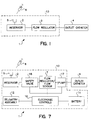
- FIG. 1 is a block diagram of an implantable drug infusion device according to the present invention.
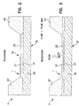
- FIG. 2 is a side view of a flow regulator according to the present invention in which the system pressure is low and the regulator membrane is not deflected.
- FIG. 3 is a side view of a flow regulator according to the present invention in which the system pressure is high and the membrane is deflected.
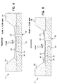
- FIG. 4 is a side view of a further embodiment of a flow regulator.
- FIGS. 5A to 5C were omitted from this application.
- FIG. 6 depicts the flow versus pressure for one embodiment of the present invention showing, in particular, the linear flow between the two pressures which may be permitted using this present invention.
- FIG. 7 is a block diagram of an implantable drug infusion device which features an integrated self-test mechanism on the flow regulator.
- FIG. 8 is a side view of a flow regulator which features an integrated self-test mechanism on the flow regulator.
- FIG. 9 depicts the change in resistance of the piezo-resistors used in the flow sensors versus reservoir pressure.
- Fig. 10 is a flow chart depicting steps employed in a self-test feature according to one embodiment of the present invention.
- FIGS. are not necessarily to scale.
- Figs. 5A, B and C are not shown in this application, but are explained below after the description of Fig. 4.
- FIG. 1 is a block diagram of an implantable drug infusion device and in particular of a passive system to deliver drugs and other therapeutic agents.
- a system 1 comprises a reservoir 2, flow regulator 3 and outlet catheter 4.
- the reservoir is a pressurizable reservoir to hold drugs and other therapeutic agents.
- Reservoir may be of a standard design, such as that used in the above mentioned Medtronic IsoMedTM implantable drug infusion system.
- Flow regulator 3 is coupled to the reservoir and the outlet catheter. Flow regulator controls the flow of material which may be transmitted from the reservoir to the outlet catheter and in particular permits the flow rate to be independent of reservoir pressure within a given pressure range.
- System may be refilled through injection port 5 through the use of a needle 6 as is well known.
- a hermetic closure 13 Surrounding all components of the implantable pump other than the outlet catheter is a hermetic closure 13 as is well known in the art.
- FIG. 2 is a side view of a flow regulator according to the present invention.
- the reservoir pressure is low.
- flow regulator comprises a membrane 21, 22 cantilevered from shoulders 23 and 24 respectively.
- membrane is circular, although other shapes may also be used, e.g. rectangular.
- the membrane is further disposed above a substrate 30 such that cavity 31 is defined.
- Outflow tract is coupled, in turn, to outlet catheter (although not shown in this view).
- Outlet catheter may be of any model desired and suited to the patient's requirements.
- the membrane may be either in the position shown or deflected any amount as permitted by substrate 30.
- shoulders and membrane are silicon and substrate is PyrexTMglass, although other materials may also be used such as titanium or tantalum.
- the areas of substrate and membranes in contact with any drug or fluid are further preferably coated with diamond or diamond-like carbon so as to inhibit any interactions between the drug or fluid and the materials. Such coatings may be selected according to the particular drug or fluid to be infused.
- FIG. 3 is a side view of a flow regulator according to the present invention in which the system pressure is high. As seen in this embodiment, the pressure of the fluid causes the membrane to be deflected and strike against substrate 30. In such a manner the fluid pathway (flow lumen 25 into cavity 31 and thereafter through outflow tract 32) is blocked by the membrane itself and all fluid flow is thus stopped.
- FIG. 4 is an additional embodiment of the present invention and, in particular, the preferred embodiment of flow regulator which features a variable flow restrictor channel 33.
- flow regulator features a variable flow restrictor channel which provides a pathway through which flow may continue even though the membrane is disposed against a surface in substrate 30.
- flow proceeds through lumen 25 into the variable flow restrictor channel 33 to the outlet 32. Because membrane strikes the top of substrate all flow is forced to go to the "beginning" of the variable flow restrictor channel. As more pressure is applied to the membrane by the fluid, the membrane is deflected to a greater degree, a greater contact area is made between the membrane and the substrate, and the fluid is forced to flow through a longer pathway through the variable flow restrictor channel.
- the length of the flow channel is directly proportional to the flow resistance.
- the increase in contact area due to pressure proportionally lengthens the distance in which the fluid flows exclusively within the flow channel.
- the flow through the restrictor channel is directly proportional to the pressure applied to the fluid within that channel.
- the restrictor channel is essentially square in shape and has a depth roughly equal to the width.
- other cross sectional shapes of restrictor channel may also be used, such as circular, or other shapes, triangular, etc.
- the channel has a width of 15 mm and depth of 10 mm which permits an essentially constant flow rate of 500 ml over a pressure range of approximately 14 to 56 kPa (2 to 8 psi) above ambient pressure
- the cross sectional area and shape of the restrictor channel is constant in the preferred embodiment, either the shape or area or both may be varied along the various portions in order to provide other flow characteristics besides those of the preferred embodiment.
- FIG. 6 is a graph showing the flow rate versus pressure of the preferred embodiment. As seen, due to the usage of the deflected leaflets in conjunction with the variable flow restrictor channel the flow rate may be caused to be constant over a pressure range.
- P1 is 14 kPa (2 psi)
- P2 is 56 kPa (8psi)
- F1 is 500 ml.
- FIG. 7 is a block diagram of an alternative embodiment of the present invention.
- a system 1 comprises a reservoir 2, flow regulator/flow sensor 7, electronic controls 10, battery 11, telemetry assembly 12 and outlet catheter 4.
- Flow regulator/flow sensor 7 is coupled to the reservoir across safety valve 16 and further coupled to the outlet catheter across pump 17.
- Flow regulator/flow sensor regulates the flow of material which may be transmitted from the reservoir to the outlet catheter by pump in a manner to the flow regulator already described above, i.e. it regulates flow such that flow rate is independent of reservoir pressure within a given pressure range.
- the flow regulator also functions as a flow sensor to permit the flow rate to be sensed such that the device can track how much drug is delivered.
- this component also permits the device to test itself so as to check and monitor the actual flow rate.
- the system may be refilled through injection port 5 through the use of a needle 6 as is well known.
- a hermetic closure 13 Surrounding all components of the implantable pump other than the outlet catheter is a hermetic closure 13 as is well known in the art.
- Electronic controls 10, battery 11, telemetry assembly 12 and pump 17 are all constructed in any manner well known in the art.
- Electronic controls are powered by battery 11 and may receive remote operation instructions via telemetry assembly 12, as is well known in the art.
- Safety valve is preferably of a design as shown in the co-pending application of Haller et al. "Implantable Infusion Device Having Safety Valve" (P-7356) filed this same day.
- FIG. 8 is a side view of a flow regulator/flow sensor used in the system of FIG. 7 As seen, this embodiment is essentially the same as that shown in FIG. 4. That is, flow regulator comprises membrane 21 cantilevered from shoulders 23 and 24 respectively disposed above a variable flow restrictor channel within substrate 30. As already discussed above, channel provides a pathway through which flow may continue even though the membrane is disposed against the surface of substrate 30.
- the flow regulator/flow sensor further features one or more piezo-resistive elements 40, 41 integral with the membrane such that deformation or bending of the leaflets is detected by the elements. Such elements are coupled to the electronic controls, which process the signals and extract information as to element deformation and thus flow through the valve. Although piezo-resistive elements are used, other types of elements may also be used, such as capacitive or inductive.
- FIG. 9 is a graph showing the change in resistance to flow versus pressure of the preferred embodiment. As seen, due to the usage of the deflected membrane in conjunction with the variable flow restrictor channel the change in resistance to flow increases in proportion to the pressure.
- FIG. 10 is a flow chart depicting the steps used of a self-test feature made possible through the one or more piezo-resistive elements 40, 41 integral with the membrane.
- this feature is used to quantify membrane deflection. This is important because, the membranes may, over time, take a set, that is exhibit a permanent deflection.
- the self test permits the membrane position to be precisely measured. Such information may be then used to assess device operation, e.g. the actual flow rate of fluid through the regulator. amount of refill required by the reservoir or device malfunction.
- this self test procedure is performed at device implant or follow-up by the physician.
- a first amount of energy is applied across one or more piezo-resistive elements 40, 41.
- a parameter indicated through the first amount of energy is sensed.
- Such parameters may include resistance, impedance or capacitance, for example. Because in the preferred embodiment the elements are piezo-resistive, then the parameter preferably sensed would be the electrical resistance in the elements. The exact type of parameter is not crucial to the self test feature, nor is whether the elements are piezo resistive or piezo capacitive, etc.
- a second amount of energy is applied across one or more piezo-resistive elements 40, 41 while a known pressure is generated in the reservoir.
- a second parameter indicated through the second amount of energy is sensed.
- the sensed second parameter is calibrated against the preceding known pressure and the quantity of membrane deflection is determined. This, in turn, indicates flow.
- the system runs a self diagnosis to determine, among other things, whether the sensed flow is within a predetermined range, if not, then the device closes a valve and shuts down. Otherwise the device uses the new data to correct the sensed deflection against the known pressure and create a new baseline for future measurements.
Landscapes
- Health & Medical Sciences (AREA)
- Engineering & Computer Science (AREA)
- Heart & Thoracic Surgery (AREA)
- Hematology (AREA)
- Veterinary Medicine (AREA)
- Vascular Medicine (AREA)
- Anesthesiology (AREA)
- Biomedical Technology (AREA)
- Public Health (AREA)
- General Health & Medical Sciences (AREA)
- Life Sciences & Earth Sciences (AREA)
- Animal Behavior & Ethology (AREA)
- Automation & Control Theory (AREA)
- Physics & Mathematics (AREA)
- General Physics & Mathematics (AREA)
- Infusion, Injection, And Reservoir Apparatuses (AREA)
Claims (16)
- Dispositif de perfusion de médicament implantable, comprenant :une enceinte hermétique ;un réservoir à fluide (2) positionné à l'intérieur de l'enceinte hermétique, le réservoir à fluide ayant un orifice de sortie de fluide ;des moyens (4) pour fournir un fluide dans le corps d'un patient ; etun régulateur de débit (3) couplé à l'orifice de sortie de fluide, le régulateur de débit étant également couplé aux moyens pour fournir un fluide dans le corps d'un patient, le régulateur de débit ayant un trajet de fluide entre l'orifice de sortie de fluide et les moyens pour fournir un fluide dans le corps d'un patient, le régulateur de débit comprenant une membrane (21, 22) et une couche inférieure (30), la membrane ayant un trou (25), grâce à quoi le trajet de fluide (31) est défini depuis le dessus de la membrane, à travers le trou, et le long de la couche inférieure (30), le régulateur de débit étant adapté à maintenir un débit de fluide constant à l'intérieur du trajet de fluide quand le fluide dans le réservoir se trouve à une pression à l'intérieur d'une plage de pression donnée ; et grâce à quoi le débit à travers le trou amène la membrane à se défléchir vers la couche inférieure en restreignant ainsi le trajet de fluide.
- Dispositif de perfusion de médicament implantable selon la revendication 1, dans lequel la membrane est en porte-à-faux depuis un épaulement (23, 24) au-dessus de la couche inférieure.
- Dispositif de perfusion de médicament implantable selon l'une ou l'autre des revendications 1 et 2, comprenant en outre des moyens (40, 41) pour déterminer une quelconque déflexion de la membrane.
- Dispositif de perfusion de médicament implantable selon la revendication 3, comprenant en outre des moyens pour calibrer la déflexion détectée de la membrane avec le débit du fluide qui s'écoule à travers le trajet de fluide.
- Dispositif de perfusion de médicament implantable selon l'une quelconque des revendications précédentes, dans lequel la couche inférieure (30) comporte un canal (32) à l'intérieur, la membrane étant en porte-à-faux depuis un épaulement (23, 24) au-dessus de la couche inférieure, grâce à quoi le débit à travers le trou amène la membrane à se défléchir et à engager la couche inférieure, permettant ainsi au trajet de fluide d'exister uniquement à l'intérieur du canal.
- Dispositif de perfusion de médicament implantable selon la revendication 5, comprenant en outre des moyens pour faire varier la longueur du canal d'écoulement.
- Dispositif de perfusion de médicament implantable selon l'une quelconque des revendications précédentes, la membrane ayant un ou plusieurs élément(s) (40, 41) indiquant la déflexion de la membrane, le dispositif comprenant encore :des moyens (10) pour appliquer une première quantité d'énergie à travers ledit un ou lesdits plusieurs élément(s) ;des moyens (7) pour détecter un paramètre indiqué via la première quantité d'énergie appliquée à travers ledit un ou lesdits plusieurs élément(s) ;des moyens (17) pour engendrer une pression connue dans le réservoir ; des moyens (10) pour appliquer une seconde quantité d'énergie à travers ledit un ou lesdits plusieurs élément(s) tandis qu'une pression connue est engendrée dans le réservoir ;des moyens (7) pour détecter un second paramètre indiqué via la seconde quantité d'énergie ;des moyens (7) pour calibrer le second paramètre détecté en fonction de la pression connue précédente et déterminer la valeur de la déflexion de la membrane.
- Dispositif de perfusion de médicament implantable selon l'une quelconque des revendications précédentes, comprenant en outre :des moyens pour déterminer une déflexion quelconque de la membrane provoquée par une pression du fluide dans le réservoir, et pour ajuster la déflexion déterminée et compenser des changements quelconques de la forme de la membrane pour donner ainsi une mesure du débit du fluide à travers le régulateur de débit.
- Régulateur de débit adapté à être incorporé dans un dispositif de perfusion de médicament implantable tel que défini dans la revendication 1, comprenant :une membrane (21, 22) ayant un trou (25) ;une couche inférieure (30) ;un trajet de fluide (31) ;la membrane étant positionnée au-dessus de la couche inférieure, le trajet de fluide étant défini depuis le dessus de la membrane, à travers le trou (25), et le long de la couche inférieure sur le côté tourné vers la membrane, grâce à quoi le débit à travers le trou amène la membrane à se défléchir et à s'engager contre une partie au moins de la couche inférieure en bloquant ainsi le trajet de fluide.
- Régulateur de débit selon la revendication 9, dans lequel le côté de la couche inférieure tourné vers la membrane comprend en outre au moins un canal qui constitue une partie du trajet de fluide, la première extrémité du canal étant en connexion avec un orifice de sortie, grâce à quoi le débit à travers le trou amène la membrane à se défléchir et à s'engager contre une partie au moins de la couche inférieure, forçant ainsi le fluide dans cette partie à s'écouler uniquement dans le canal.
- Régulateur de débit selon la revendication 10, dans lequel la forme et la longueur du canal sont ainsi conçues qu'une augmentation de pression engendre une augmentation de la zone de contact entre la membrane et la couche inférieure, définissant de ce fait un segment additionnel du canal dans lequel le fluide est confiné, ladite configuration permettant un ajustement approprié des caractéristiques débit/pression.
- Régulateur de débit selon la revendication 11, dans lequel la section du canal est constante.
- Régulateur de débit selon la revendication 11, dans lequel la forme et la longueur du canal sont ainsi conçues que la résistance au fluide est proportionnelle à la pression, impliquant de ce fait un débit indépendant de la pression.
- Régulateur de débit selon l'une ou l'autre des revendications 12 et 13, dans lequel le canal est une gorge de forme spiralée.
- Régulateur de débit selon l'une quelconque des revendications 9 à 14, dans lequel la membrane inclut en outre des moyens pour détecter la déflexion de la membrane.
- Régulateur de débit selon l'une quelconque des revendications 9 à 15, dans lequel le trajet de fluide est obstrué quand la membrane a atteint un degré prédéterminé de déflexion.
Applications Claiming Priority (3)
| Application Number | Priority Date | Filing Date | Title |
|---|---|---|---|
| US09/017,194 US6203523B1 (en) | 1998-02-02 | 1998-02-02 | Implantable drug infusion device having a flow regulator |
| US17194 | 1998-02-02 | ||
| PCT/US1999/002136 WO1999038552A1 (fr) | 1998-02-02 | 1999-02-01 | Dispositif de perfusion de medicament implantable comprenant un regulateur de debit |
Publications (2)
| Publication Number | Publication Date |
|---|---|
| EP1053035A1 EP1053035A1 (fr) | 2000-11-22 |
| EP1053035B1 true EP1053035B1 (fr) | 2004-09-15 |
Family
ID=21781244
Family Applications (1)
| Application Number | Title | Priority Date | Filing Date |
|---|---|---|---|
| EP99904522A Expired - Lifetime EP1053035B1 (fr) | 1998-02-02 | 1999-02-01 | Dispositif de perfusion de medicament implantable comprenant un regulateur de debit |
Country Status (5)
| Country | Link |
|---|---|
| US (2) | US6203523B1 (fr) |
| EP (1) | EP1053035B1 (fr) |
| AU (1) | AU2490599A (fr) |
| DE (1) | DE69920174T2 (fr) |
| WO (1) | WO1999038552A1 (fr) |
Cited By (1)
| Publication number | Priority date | Publication date | Assignee | Title |
|---|---|---|---|---|
| KR20190061318A (ko) * | 2017-11-27 | 2019-06-05 | 재단법인 대구경북첨단의료산업진흥재단 | 약물 주입 장치 |
Families Citing this family (107)
| Publication number | Priority date | Publication date | Assignee | Title |
|---|---|---|---|---|
| US6203523B1 (en) | 1998-02-02 | 2001-03-20 | Medtronic Inc | Implantable drug infusion device having a flow regulator |
| US6305381B1 (en) | 1998-02-02 | 2001-10-23 | Medtronic Inc. | System for locating implantable medical device |
| AU2570999A (en) * | 1998-02-02 | 1999-08-16 | Medtronic, Inc. | Implantable drug infusion device having a safety valve |
| EP1154691A4 (fr) * | 1999-01-05 | 2004-07-07 | Massachusetts Eye & Ear Infirm | Administration ciblee de medicament a liberation regulee vers la retine et la choroide a travers la sclerotique |
| US6638263B1 (en) | 1999-10-12 | 2003-10-28 | Durect Corporation | Regulation of drug delivery through flow diversion |
| US6589205B1 (en) * | 1999-12-17 | 2003-07-08 | Advanced Bionica Corporation | Externally-controllable constant-flow medication delivery system |
| US6592519B1 (en) * | 2000-04-28 | 2003-07-15 | Medtronic, Inc. | Smart microfluidic device with universal coating |
| EP1387671A1 (fr) | 2001-05-03 | 2004-02-11 | MASSACHUSETTS EYE & EAR INFIRMARY | Dispositif d'administration de medicament implantable et utilisation associee |
| US7876294B2 (en) * | 2002-03-05 | 2011-01-25 | Nec Corporation | Image display and its control method |
| WO2003092665A2 (fr) * | 2002-05-02 | 2003-11-13 | Massachusetts Eye And Ear Infirmary | Systemes oculaires de distribution de medicament et utilisation associee |
| US20030236489A1 (en) | 2002-06-21 | 2003-12-25 | Baxter International, Inc. | Method and apparatus for closed-loop flow control system |
| US7338433B2 (en) | 2002-08-13 | 2008-03-04 | Allergan, Inc. | Remotely adjustable gastric banding method |
| BR0306183A (pt) | 2002-08-28 | 2004-10-19 | Inamed Medical Products Corp | Dispositivo de enfaixamento gástrico resistente à fadiga |
| US6966325B2 (en) * | 2002-09-20 | 2005-11-22 | Advanced Neuromodulation Systems, Inc. | Method for manipulating dosage control apparatus |
| US7150741B2 (en) * | 2002-09-20 | 2006-12-19 | Advanced Neuromodulation Systems, Inc. | Programmable dose control module |
| US20040068224A1 (en) * | 2002-10-02 | 2004-04-08 | Couvillon Lucien Alfred | Electroactive polymer actuated medication infusion pumps |
| US20060167435A1 (en) * | 2003-02-18 | 2006-07-27 | Adamis Anthony P | Transscleral drug delivery device and related methods |
| WO2004087237A2 (fr) * | 2003-03-27 | 2004-10-14 | Medical Research Products-A, Inc. | Dispositif implantable de distribution de medicament faisant intervenir un regulateur de pression |
| JP4722850B2 (ja) * | 2003-09-15 | 2011-07-13 | アラーガン、インコーポレイテッド | 植込み式デバイス締付けシステムおよび使用方法 |
| US8317770B2 (en) * | 2006-04-06 | 2012-11-27 | Medtronic, Inc. | Systems and methods of identifying catheter malfunctions using pressure sensing |
| US9033920B2 (en) * | 2003-10-02 | 2015-05-19 | Medtronic, Inc. | Determining catheter status |
| US8323244B2 (en) * | 2007-03-30 | 2012-12-04 | Medtronic, Inc. | Catheter malfunction determinations using physiologic pressure |
| US7320676B2 (en) * | 2003-10-02 | 2008-01-22 | Medtronic, Inc. | Pressure sensing in implantable medical devices |
| US9138537B2 (en) | 2003-10-02 | 2015-09-22 | Medtronic, Inc. | Determining catheter status |
| US7022116B2 (en) * | 2003-10-23 | 2006-04-04 | Medtronic, Inc. | Method for monitoring bolus delivery |
| AU2005208721B2 (en) | 2004-01-23 | 2010-09-23 | Boston Scientific Scimed, Inc. | Releasably-securable one-piece adjustable gastric band |
| PL1670362T3 (pl) * | 2004-01-23 | 2011-05-31 | Apollo Endosurgery Inc | Układ mocujący wszczepiane urządzenie i sposoby jego stosowania |
| US7867194B2 (en) | 2004-01-29 | 2011-01-11 | The Charles Stark Draper Laboratory, Inc. | Drug delivery apparatus |
| DK1725193T3 (da) * | 2004-03-08 | 2009-11-30 | Allergan Medical S A | Lukkesystem til rörformede organer |
| ATE517652T1 (de) * | 2004-03-18 | 2011-08-15 | Allergan Inc | Vorrichtung zur volumeneinstellung intragastraler ballons |
| US7217251B2 (en) * | 2004-04-22 | 2007-05-15 | Medtronic, Inc. | Pressure relief methods in a medical catheter system |
| US7513884B2 (en) * | 2004-04-22 | 2009-04-07 | Medtronic, Inc. | Branching catheter systems with diagnostic components |
| US7766885B2 (en) * | 2004-06-07 | 2010-08-03 | Medtronic, Inc. | Drug delivery system |
| US8251981B2 (en) * | 2004-06-07 | 2012-08-28 | Medtronic, Inc. | Regulator |
| US8246569B1 (en) | 2004-08-17 | 2012-08-21 | California Institute Of Technology | Implantable intraocular pressure drain |
| US7231829B2 (en) * | 2005-03-31 | 2007-06-19 | Medtronic, Inc. | Monolithic integrated circuit/pressure sensor on pacing lead |
| US8251888B2 (en) | 2005-04-13 | 2012-08-28 | Mitchell Steven Roslin | Artificial gastric valve |
| US7637892B2 (en) * | 2005-05-10 | 2009-12-29 | Palyon Medical (Bvi) Limited | Variable flow infusion pump system |
| US8114055B2 (en) | 2005-05-10 | 2012-02-14 | Palyon Medical (Bvi) Limited | Implantable pump with infinitely variable resistor |
| US8211060B2 (en) | 2005-05-10 | 2012-07-03 | Palyon Medical (Bvi) Limited | Reduced size implantable pump |
| US8915893B2 (en) | 2005-05-10 | 2014-12-23 | Palyon Medical (Bvi) Limited | Variable flow infusion pump system |
| US20060276744A1 (en) * | 2005-05-20 | 2006-12-07 | Falk Theodore J | Configuration for drug delivery systems |
| US20070106271A1 (en) | 2005-11-09 | 2007-05-10 | Searete Llc, A Limited Liability Corporation | Remote control of substance delivery system |
| US8273071B2 (en) | 2006-01-18 | 2012-09-25 | The Invention Science Fund I, Llc | Remote controller for substance delivery system |
| US8083710B2 (en) | 2006-03-09 | 2011-12-27 | The Invention Science Fund I, Llc | Acoustically controlled substance delivery device |
| US20070106277A1 (en) * | 2005-11-09 | 2007-05-10 | Searete Llc, A Limited Liability Corporation Of The State Of Delaware | Remote controller for substance delivery system |
| US9474712B2 (en) * | 2005-11-09 | 2016-10-25 | Gearbox, Llc | In situ reaction device |
| US8992511B2 (en) * | 2005-11-09 | 2015-03-31 | The Invention Science Fund I, Llc | Acoustically controlled substance delivery device |
| US8936590B2 (en) * | 2005-11-09 | 2015-01-20 | The Invention Science Fund I, Llc | Acoustically controlled reaction device |
| US8273075B2 (en) * | 2005-12-13 | 2012-09-25 | The Invention Science Fund I, Llc | Osmotic pump with remotely controlled osmotic flow rate |
| US20070129678A1 (en) * | 2005-12-06 | 2007-06-07 | Medtronic, Inc. | Regulator |
| US9616223B2 (en) | 2005-12-30 | 2017-04-11 | Medtronic, Inc. | Media-exposed interconnects for transducers |
| US8043206B2 (en) | 2006-01-04 | 2011-10-25 | Allergan, Inc. | Self-regulating gastric band with pressure data processing |
| US7798954B2 (en) | 2006-01-04 | 2010-09-21 | Allergan, Inc. | Hydraulic gastric band with collapsible reservoir |
| EP2319558B1 (fr) | 2006-03-14 | 2014-05-21 | University Of Southern California | Dispositif Mems de livraison d'agents therapeutiques |
| US8444609B2 (en) | 2006-04-28 | 2013-05-21 | Medtronic, Inc. | Implantable therapeutic substance delivery system with catheter access port block and method of use |
| US8100871B2 (en) | 2006-04-28 | 2012-01-24 | Medtronic, Inc. | Implantable therapeutic substance delivery system with catheter access port control and method of use |
| US20070260174A1 (en) * | 2006-05-05 | 2007-11-08 | Searete Llc | Detecting a failure to maintain a regimen |
| US20080097249A1 (en) * | 2006-10-20 | 2008-04-24 | Ellipse Technologies, Inc. | External sensing system for gastric restriction devices |
| US8092386B1 (en) | 2006-12-22 | 2012-01-10 | Pacesetter, Inc. | Method and implantable system for blood-glucose concentration monitoring |
| US9046192B2 (en) | 2007-01-31 | 2015-06-02 | The Charles Stark Draper Laboratory, Inc. | Membrane-based fluid control in microfluidic devices |
| US9044537B2 (en) | 2007-03-30 | 2015-06-02 | Medtronic, Inc. | Devices and methods for detecting catheter complications |
| US20090112155A1 (en) * | 2007-10-30 | 2009-04-30 | Lifescan, Inc. | Micro Diaphragm Pump |
| JP5542691B2 (ja) | 2007-12-20 | 2014-07-09 | ユニバーシティ オブ サザン カリフォルニア | 治療薬を送達するための装置および方法 |
| ES2577502T3 (es) | 2008-01-03 | 2016-07-15 | University Of Southern California | Dispositivos implantables de administración de fármacos y aparato para recargar los dispositivos |
| US20100324504A1 (en) * | 2008-02-09 | 2010-12-23 | Eric Chappel | Passive flow regulator for infusion of medicaments |
| US9333297B2 (en) | 2008-05-08 | 2016-05-10 | Minipumps, Llc | Drug-delivery pump with intelligent control |
| EP2320989B1 (fr) | 2008-05-08 | 2015-03-11 | MiniPumps, LLC | Pompes implantables et canules à cet effet |
| US8231608B2 (en) | 2008-05-08 | 2012-07-31 | Minipumps, Llc | Drug-delivery pumps and methods of manufacture |
| CN102202706A (zh) | 2008-05-08 | 2011-09-28 | 迷你泵有限责任公司 | 可植入药物传送装置与用于填充该装置的设备和方法 |
| EP2153855A1 (fr) * | 2008-08-16 | 2010-02-17 | Debiotech S.A. | Régulateur d'écoulement de fluides passifs pour l'administration de médicaments à débit constant et dispositif de perfusion de médicaments correspondant |
| US8317677B2 (en) * | 2008-10-06 | 2012-11-27 | Allergan, Inc. | Mechanical gastric band with cushions |
| US20100185049A1 (en) * | 2008-10-22 | 2010-07-22 | Allergan, Inc. | Dome and screw valves for remotely adjustable gastric banding systems |
| WO2010090858A2 (fr) * | 2009-01-21 | 2010-08-12 | Medtronic, Inc. | Systèmes cathéters comportant des réducteurs de débit |
| US8126736B2 (en) * | 2009-01-23 | 2012-02-28 | Warsaw Orthopedic, Inc. | Methods and systems for diagnosing, treating, or tracking spinal disorders |
| US8685093B2 (en) * | 2009-01-23 | 2014-04-01 | Warsaw Orthopedic, Inc. | Methods and systems for diagnosing, treating, or tracking spinal disorders |
| US8630692B2 (en) | 2009-04-30 | 2014-01-14 | Pacesetter, Inc. | Method and implantable system for blood-glucose concentration monitoring using parallel methodologies |
| WO2010127248A2 (fr) * | 2009-05-01 | 2010-11-04 | Allergan, Inc. | Bande gastrique laparoscopique avec agents actifs |
| US20110184229A1 (en) * | 2009-05-01 | 2011-07-28 | Allergan, Inc. | Laparoscopic gastric band with active agents |
| JP5758388B2 (ja) | 2009-08-18 | 2015-08-05 | ミニパンプス, エルエルシー | 適応制御を有する電解質薬物送達ポンプ |
| US20110137112A1 (en) * | 2009-08-28 | 2011-06-09 | Allergan, Inc. | Gastric band with electric stimulation |
| WO2011031400A2 (fr) * | 2009-08-28 | 2011-03-17 | Allergan, Inc. | Bande gastrique avec stimulation électrique |
| EP2359886A1 (fr) | 2010-02-12 | 2011-08-24 | Debiotech S.A. | Régulateur de débit passif et micromécanique |
| US8758221B2 (en) * | 2010-02-24 | 2014-06-24 | Apollo Endosurgery, Inc. | Source reservoir with potential energy for remotely adjustable gastric banding system |
| US8840541B2 (en) | 2010-02-25 | 2014-09-23 | Apollo Endosurgery, Inc. | Pressure sensing gastric banding system |
| US20110270024A1 (en) | 2010-04-29 | 2011-11-03 | Allergan, Inc. | Self-adjusting gastric band having various compliant components |
| US9028394B2 (en) | 2010-04-29 | 2015-05-12 | Apollo Endosurgery, Inc. | Self-adjusting mechanical gastric band |
| US9044298B2 (en) | 2010-04-29 | 2015-06-02 | Apollo Endosurgery, Inc. | Self-adjusting gastric band |
| US20110270025A1 (en) | 2010-04-30 | 2011-11-03 | Allergan, Inc. | Remotely powered remotely adjustable gastric band system |
| US8517915B2 (en) | 2010-06-10 | 2013-08-27 | Allergan, Inc. | Remotely adjustable gastric banding system |
| US20120059216A1 (en) | 2010-09-07 | 2012-03-08 | Allergan, Inc. | Remotely adjustable gastric banding system |
| US8961393B2 (en) | 2010-11-15 | 2015-02-24 | Apollo Endosurgery, Inc. | Gastric band devices and drive systems |
| CA2825757C (fr) | 2011-02-02 | 2019-09-03 | The Charles Stark Draper Laboratory, Inc. | Appareil d'administration de medicaments |
| US9919099B2 (en) | 2011-03-14 | 2018-03-20 | Minipumps, Llc | Implantable drug pumps and refill devices therefor |
| US10286146B2 (en) | 2011-03-14 | 2019-05-14 | Minipumps, Llc | Implantable drug pumps and refill devices therefor |
| US9603997B2 (en) | 2011-03-14 | 2017-03-28 | Minipumps, Llc | Implantable drug pumps and refill devices therefor |
| US8876694B2 (en) | 2011-12-07 | 2014-11-04 | Apollo Endosurgery, Inc. | Tube connector with a guiding tip |
| US8961394B2 (en) | 2011-12-20 | 2015-02-24 | Apollo Endosurgery, Inc. | Self-sealing fluid joint for use with a gastric band |
| US8568360B2 (en) | 2011-12-28 | 2013-10-29 | Palyon Medical (Bvi) Limited | Programmable implantable pump design |
| US9381039B2 (en) | 2012-03-21 | 2016-07-05 | Medtronic, Inc. | Filling methods and apparatus for implanted medical therapy delivery devices |
| DE102012205262B4 (de) | 2012-03-30 | 2024-09-26 | Ford Global Technologies, Llc | Variabler Flusswiderstand |
| EP2754935A1 (fr) | 2013-01-10 | 2014-07-16 | Debiotech S.A. | Régulateur d'écoulement passif réglable |
| US9539382B2 (en) | 2013-03-12 | 2017-01-10 | Medtronic, Inc. | Stepped catheters with flow restrictors and infusion systems using the same |
| US10533669B2 (en) * | 2016-12-01 | 2020-01-14 | Baker Hughes, A Ge Company, Llc | Bi-directional flow control valve |
| US12115348B2 (en) | 2018-11-20 | 2024-10-15 | Cochlear Limited | Selectable drug delivery rate device |
| US12290660B2 (en) | 2019-01-08 | 2025-05-06 | Cochlear Limited | Heating elements for thermally-driven phase transition implantable micropump |
| CN113786554B (zh) * | 2021-09-27 | 2023-07-18 | 时新(上海)产品设计有限公司 | 适用微剂量输注的安全阀组件、微剂量分泌泵及胰岛素泵 |
Family Cites Families (22)
| Publication number | Priority date | Publication date | Assignee | Title |
|---|---|---|---|---|
| FR1299719A (fr) * | 1961-06-16 | 1962-07-27 | Citroen Sa Andre | Régulateur de débits notamment pour circuit hydraulique |
| US3731681A (en) * | 1970-05-18 | 1973-05-08 | Univ Minnesota | Implantable indusion pump |
| IL50771A (en) * | 1976-10-27 | 1988-08-31 | Bron Dan | Fluid flow-rate control device |
| US4129042A (en) | 1977-11-18 | 1978-12-12 | Signetics Corporation | Semiconductor transducer packaged assembly |
| US4299220A (en) * | 1979-05-03 | 1981-11-10 | The Regents Of The University Of Minnesota | Implantable drug infusion regulator |
| US4447224A (en) * | 1982-09-20 | 1984-05-08 | Infusaid Corporation | Variable flow implantable infusion apparatus |
| IL69431A (en) * | 1983-08-04 | 1987-12-31 | Omikron Scient Ltd | Liquid delivery system particularly useful as an implantable micro-pump for delivering insulin or other drugs |
| US4666429A (en) * | 1986-02-26 | 1987-05-19 | Intelligent Medicine, Inc. | Infusion device having improved valving apparatus |
| AU635262B2 (en) * | 1989-05-11 | 1993-03-18 | Bespak Plc | Pump apparatus for biomedical use |
| IL90950A (en) * | 1989-07-12 | 1992-08-18 | Bron Dan | Low-output flow regulator |
| US5061242A (en) * | 1989-07-18 | 1991-10-29 | Infusaid, Inc. | Adjustable implantable drug infusion system |
| KR910012538A (ko) | 1989-12-27 | 1991-08-08 | 야마무라 가쯔미 | 마이크로 펌프 및 그 제조 방법 |
| DE4103706A1 (de) | 1990-07-18 | 1992-01-30 | Bosch Gmbh Robert | Druckgeber zur druckerfassung im brennraum von brennkraftmaschinen |
| EP0498863B1 (fr) | 1990-08-31 | 1995-07-26 | Westonbridge International Limited | Soupape equipee d'un detecteur de position et micropompe integree a ladite soupape |
| US5189777A (en) | 1990-12-07 | 1993-03-02 | Wisconsin Alumni Research Foundation | Method of producing micromachined differential pressure transducers |
| US5163920A (en) * | 1991-01-30 | 1992-11-17 | Infusaid Inc. | Flow regulator damper element |
| US5328460A (en) * | 1991-06-21 | 1994-07-12 | Pacesetter Infusion, Ltd. | Implantable medication infusion pump including self-contained acoustic fault detection apparatus |
| US5377524A (en) | 1992-06-22 | 1995-01-03 | The Regents Of The University Of Michigan | Self-testing capacitive pressure transducer and method |
| US5281210A (en) * | 1992-09-18 | 1994-01-25 | Infusaid, Inc. | Accumulator for implantable pump |
| EP0618450A1 (fr) | 1993-03-30 | 1994-10-05 | Siemens Aktiengesellschaft | Capteur d'accélération |
| WO1995009987A1 (fr) | 1993-10-04 | 1995-04-13 | Research International, Inc. | Regulateurs de debit micro-usines |
| US6203523B1 (en) | 1998-02-02 | 2001-03-20 | Medtronic Inc | Implantable drug infusion device having a flow regulator |
-
1998
- 1998-02-02 US US09/017,194 patent/US6203523B1/en not_active Expired - Lifetime
-
1999
- 1999-02-01 AU AU24905/99A patent/AU2490599A/en not_active Abandoned
- 1999-02-01 WO PCT/US1999/002136 patent/WO1999038552A1/fr not_active Ceased
- 1999-02-01 DE DE69920174T patent/DE69920174T2/de not_active Expired - Lifetime
- 1999-02-01 EP EP99904522A patent/EP1053035B1/fr not_active Expired - Lifetime
-
2000
- 2000-11-15 US US09/712,237 patent/US6878135B1/en not_active Expired - Lifetime
Cited By (1)
| Publication number | Priority date | Publication date | Assignee | Title |
|---|---|---|---|---|
| KR20190061318A (ko) * | 2017-11-27 | 2019-06-05 | 재단법인 대구경북첨단의료산업진흥재단 | 약물 주입 장치 |
Also Published As
| Publication number | Publication date |
|---|---|
| EP1053035A1 (fr) | 2000-11-22 |
| US6203523B1 (en) | 2001-03-20 |
| WO1999038552A1 (fr) | 1999-08-05 |
| DE69920174T2 (de) | 2005-09-29 |
| US6878135B1 (en) | 2005-04-12 |
| DE69920174D1 (de) | 2004-10-21 |
| AU2490599A (en) | 1999-08-16 |
Similar Documents
| Publication | Publication Date | Title |
|---|---|---|
| EP1053035B1 (fr) | Dispositif de perfusion de medicament implantable comprenant un regulateur de debit | |
| JP7174089B2 (ja) | 液剤を投薬する計量システムを有するポンプ・エンジン | |
| US4447224A (en) | Variable flow implantable infusion apparatus | |
| US7637897B2 (en) | Implantable pump with integrated refill detection | |
| US6620151B2 (en) | Non-constant pressure infusion pump | |
| US20200054822A1 (en) | System and method for controlling administration of medical fluid | |
| US6485465B2 (en) | Methods, apparatuses, and uses for infusion pump fluid pressure and force detection | |
| US8961466B2 (en) | Programmable implantable pump design | |
| EP2280750B1 (fr) | Dispositif de perfusion commandé par un détecteur d'écoulement | |
| EP2648606B1 (fr) | Appareil de perfusion doté d'un indicateur d'écoulement | |
| KR20090093990A (ko) | 변동 유량 주입 펌프 시스템 | |
| JP2002541573A (ja) | モノリシック高性能小形流量調節ユニット | |
| AU2002236842A1 (en) | Non-constant pressure infusion pump | |
| KR101952322B1 (ko) | 수액세트용 유량조절장치 | |
| EP3405232B1 (fr) | Dispositifs de perfusion ambulatoire et procédés associés | |
| AU2015268574B2 (en) | Infusion apparatus with flow indicator | |
| US20080077079A1 (en) | Liquid Dosing Arrangement |
Legal Events
| Date | Code | Title | Description |
|---|---|---|---|
| PUAI | Public reference made under article 153(3) epc to a published international application that has entered the european phase |
Free format text: ORIGINAL CODE: 0009012 |
|
| 17P | Request for examination filed |
Effective date: 20000830 |
|
| AK | Designated contracting states |
Kind code of ref document: A1 Designated state(s): CH DE ES FR GB IE IT LI NL SE |
|
| RBV | Designated contracting states (corrected) |
Designated state(s): CH DE ES FR GB IE IT LI NL SE |
|
| 17Q | First examination report despatched |
Effective date: 20030227 |
|
| GRAP | Despatch of communication of intention to grant a patent |
Free format text: ORIGINAL CODE: EPIDOSNIGR1 |
|
| GRAS | Grant fee paid |
Free format text: ORIGINAL CODE: EPIDOSNIGR3 |
|
| GRAA | (expected) grant |
Free format text: ORIGINAL CODE: 0009210 |
|
| RAP1 | Party data changed (applicant data changed or rights of an application transferred) |
Owner name: MEDTRONIC, INC. |
|
| AK | Designated contracting states |
Kind code of ref document: B1 Designated state(s): CH DE ES FR GB IE IT LI NL SE |
|
| PG25 | Lapsed in a contracting state [announced via postgrant information from national office to epo] |
Ref country code: NL Free format text: LAPSE BECAUSE OF FAILURE TO SUBMIT A TRANSLATION OF THE DESCRIPTION OR TO PAY THE FEE WITHIN THE PRESCRIBED TIME-LIMIT Effective date: 20040915 Ref country code: LI Free format text: LAPSE BECAUSE OF FAILURE TO SUBMIT A TRANSLATION OF THE DESCRIPTION OR TO PAY THE FEE WITHIN THE PRESCRIBED TIME-LIMIT Effective date: 20040915 |
|
| REG | Reference to a national code |
Ref country code: GB Ref legal event code: FG4D Ref country code: CH Ref legal event code: EP |
|
| REG | Reference to a national code |
Ref country code: IE Ref legal event code: FG4D |
|
| REF | Corresponds to: |
Ref document number: 69920174 Country of ref document: DE Date of ref document: 20041021 Kind code of ref document: P |
|
| PG25 | Lapsed in a contracting state [announced via postgrant information from national office to epo] |
Ref country code: SE Free format text: LAPSE BECAUSE OF FAILURE TO SUBMIT A TRANSLATION OF THE DESCRIPTION OR TO PAY THE FEE WITHIN THE PRESCRIBED TIME-LIMIT Effective date: 20041215 |
|
| REG | Reference to a national code |
Ref country code: CH Ref legal event code: PL |
|
| NLV1 | Nl: lapsed or annulled due to failure to fulfill the requirements of art. 29p and 29m of the patents act | ||
| REG | Reference to a national code |
Ref country code: CH Ref legal event code: NV Representative=s name: A. BRAUN, BRAUN, HERITIER, ESCHMANN AG PATENTANWAE Ref country code: CH Ref legal event code: AEN Free format text: DAS PATENT IST AUF GRUND DES WEITERBEHANDLUNGSANTRAGS VOM 15.06.2005 REAKTIVIERT WORDEN. |
|
| PLBE | No opposition filed within time limit |
Free format text: ORIGINAL CODE: 0009261 |
|
| STAA | Information on the status of an ep patent application or granted ep patent |
Free format text: STATUS: NO OPPOSITION FILED WITHIN TIME LIMIT |
|
| PGFP | Annual fee paid to national office [announced via postgrant information from national office to epo] |
Ref country code: IE Payment date: 20050728 Year of fee payment: 7 |
|
| ET | Fr: translation filed | ||
| 26N | No opposition filed |
Effective date: 20050616 |
|
| NLXE | Nl: other communications concerning ep-patents (part 3 heading xe) |
Free format text: A REQUEST FOR RESTORATION TO THE PRIOR STATE (ARTICLE 23 OF THE PATENTS ACT 1995) HAS BEEN FILED ON 20050726. |
|
| PG25 | Lapsed in a contracting state [announced via postgrant information from national office to epo] |
Ref country code: IE Free format text: LAPSE BECAUSE OF NON-PAYMENT OF DUE FEES Effective date: 20060201 |
|
| REG | Reference to a national code |
Ref country code: IE Ref legal event code: MM4A |
|
| NLXE | Nl: other communications concerning ep-patents (part 3 heading xe) |
Free format text: THE REQUEST FOR RESTORATION TO THE PRIOR STATE AS PROVIDED FOR IN ARTICLE 23 OF THE PATENTS ACT 1995 (SEE PUBLICATION IN HEADING XE OF THE PATENT BULLETIN OF 20051003/10) HAS BEEN REJECTED. |
|
| REG | Reference to a national code |
Ref country code: CH Ref legal event code: PFA Owner name: MEDTRONIC, INC. Free format text: MEDTRONIC, INC.#710 MEDTRONIC PARKWAY#MINNEAPOLIS, MINNESOTA 55432-5604 (US) -TRANSFER TO- MEDTRONIC, INC.#710 MEDTRONIC PARKWAY#MINNEAPOLIS, MINNESOTA 55432-5604 (US) |
|
| PG25 | Lapsed in a contracting state [announced via postgrant information from national office to epo] |
Ref country code: ES Free format text: LAPSE BECAUSE OF NON-PAYMENT OF DUE FEES Effective date: 20050228 |
|
| PGFP | Annual fee paid to national office [announced via postgrant information from national office to epo] |
Ref country code: IT Payment date: 20090214 Year of fee payment: 11 |
|
| PGFP | Annual fee paid to national office [announced via postgrant information from national office to epo] |
Ref country code: GB Payment date: 20100107 Year of fee payment: 12 |
|
| PG25 | Lapsed in a contracting state [announced via postgrant information from national office to epo] |
Ref country code: IT Free format text: LAPSE BECAUSE OF NON-PAYMENT OF DUE FEES Effective date: 20100201 |
|
| GBPC | Gb: european patent ceased through non-payment of renewal fee |
Effective date: 20110201 |
|
| PG25 | Lapsed in a contracting state [announced via postgrant information from national office to epo] |
Ref country code: GB Free format text: LAPSE BECAUSE OF NON-PAYMENT OF DUE FEES Effective date: 20110201 |
|
| REG | Reference to a national code |
Ref country code: CH Ref legal event code: PCAR Free format text: NEW ADDRESS: HOLBEINSTRASSE 36-38, 4051 BASEL (CH) |
|
| REG | Reference to a national code |
Ref country code: FR Ref legal event code: PLFP Year of fee payment: 18 |
|
| REG | Reference to a national code |
Ref country code: FR Ref legal event code: PLFP Year of fee payment: 19 |
|
| REG | Reference to a national code |
Ref country code: FR Ref legal event code: PLFP Year of fee payment: 20 |
|
| PGFP | Annual fee paid to national office [announced via postgrant information from national office to epo] |
Ref country code: CH Payment date: 20180227 Year of fee payment: 20 Ref country code: DE Payment date: 20180227 Year of fee payment: 20 |
|
| PGFP | Annual fee paid to national office [announced via postgrant information from national office to epo] |
Ref country code: FR Payment date: 20180227 Year of fee payment: 20 |
|
| REG | Reference to a national code |
Ref country code: DE Ref legal event code: R071 Ref document number: 69920174 Country of ref document: DE |
|
| REG | Reference to a national code |
Ref country code: CH Ref legal event code: PL |