EP1053200B1 - Rouleau-guide - Google Patents
Rouleau-guide Download PDFInfo
- Publication number
- EP1053200B1 EP1053200B1 EP99915467A EP99915467A EP1053200B1 EP 1053200 B1 EP1053200 B1 EP 1053200B1 EP 99915467 A EP99915467 A EP 99915467A EP 99915467 A EP99915467 A EP 99915467A EP 1053200 B1 EP1053200 B1 EP 1053200B1
- Authority
- EP
- European Patent Office
- Prior art keywords
- guide roll
- expansion elements
- web
- expansion
- elements
- Prior art date
- Legal status (The legal status is an assumption and is not a legal conclusion. Google has not performed a legal analysis and makes no representation as to the accuracy of the status listed.)
- Expired - Lifetime
Links
- 230000004888 barrier function Effects 0.000 claims description 10
- 239000012858 resilient material Substances 0.000 claims 1
- 238000011144 upstream manufacturing Methods 0.000 claims 1
- 239000012530 fluid Substances 0.000 description 4
- 239000011324 bead Substances 0.000 description 3
- 238000012937 correction Methods 0.000 description 3
- 239000013013 elastic material Substances 0.000 description 3
- 238000010586 diagram Methods 0.000 description 2
- 210000002445 nipple Anatomy 0.000 description 2
- 239000004033 plastic Substances 0.000 description 2
- 229920003023 plastic Polymers 0.000 description 2
- 238000007789 sealing Methods 0.000 description 2
- 238000009423 ventilation Methods 0.000 description 2
- 244000059549 Borneo rubber Species 0.000 description 1
- 229910000906 Bronze Inorganic materials 0.000 description 1
- 239000006004 Quartz sand Substances 0.000 description 1
- VYPSYNLAJGMNEJ-UHFFFAOYSA-N Silicium dioxide Chemical compound O=[Si]=O VYPSYNLAJGMNEJ-UHFFFAOYSA-N 0.000 description 1
- 239000004809 Teflon Substances 0.000 description 1
- 229920006362 Teflon® Polymers 0.000 description 1
- 230000002146 bilateral effect Effects 0.000 description 1
- 239000010974 bronze Substances 0.000 description 1
- KUNSUQLRTQLHQQ-UHFFFAOYSA-N copper tin Chemical compound [Cu].[Sn] KUNSUQLRTQLHQQ-UHFFFAOYSA-N 0.000 description 1
- 239000010431 corundum Substances 0.000 description 1
- 229910052593 corundum Inorganic materials 0.000 description 1
- 229920001971 elastomer Polymers 0.000 description 1
- 239000000463 material Substances 0.000 description 1
- 229920002635 polyurethane Polymers 0.000 description 1
- 239000004814 polyurethane Substances 0.000 description 1
- 239000011148 porous material Substances 0.000 description 1
- 239000005871 repellent Substances 0.000 description 1
- 230000002940 repellent Effects 0.000 description 1
- 230000003746 surface roughness Effects 0.000 description 1
- 230000037303 wrinkles Effects 0.000 description 1
Images


Classifications
-
- B—PERFORMING OPERATIONS; TRANSPORTING
- B65—CONVEYING; PACKING; STORING; HANDLING THIN OR FILAMENTARY MATERIAL
- B65H—HANDLING THIN OR FILAMENTARY MATERIAL, e.g. SHEETS, WEBS, CABLES
- B65H27/00—Special constructions, e.g. surface features, of feed or guide rollers for webs
-
- B—PERFORMING OPERATIONS; TRANSPORTING
- B65—CONVEYING; PACKING; STORING; HANDLING THIN OR FILAMENTARY MATERIAL
- B65H—HANDLING THIN OR FILAMENTARY MATERIAL, e.g. SHEETS, WEBS, CABLES
- B65H23/00—Registering, tensioning, smoothing or guiding webs
- B65H23/02—Registering, tensioning, smoothing or guiding webs transversely
- B65H23/022—Registering, tensioning, smoothing or guiding webs transversely by tentering devices
- B65H23/025—Registering, tensioning, smoothing or guiding webs transversely by tentering devices by rollers
- B65H23/0251—Registering, tensioning, smoothing or guiding webs transversely by tentering devices by rollers with a straight axis
-
- B—PERFORMING OPERATIONS; TRANSPORTING
- B65—CONVEYING; PACKING; STORING; HANDLING THIN OR FILAMENTARY MATERIAL
- B65H—HANDLING THIN OR FILAMENTARY MATERIAL, e.g. SHEETS, WEBS, CABLES
- B65H23/00—Registering, tensioning, smoothing or guiding webs
- B65H23/02—Registering, tensioning, smoothing or guiding webs transversely
- B65H23/032—Controlling transverse register of web
- B65H23/038—Controlling transverse register of web by rollers
-
- B—PERFORMING OPERATIONS; TRANSPORTING
- B65—CONVEYING; PACKING; STORING; HANDLING THIN OR FILAMENTARY MATERIAL
- B65H—HANDLING THIN OR FILAMENTARY MATERIAL, e.g. SHEETS, WEBS, CABLES
- B65H2404/00—Parts for transporting or guiding the handled material
- B65H2404/10—Rollers
- B65H2404/11—Details of cross-section or profile
- B65H2404/112—Means for varying cross-section
- B65H2404/1121—Means for varying cross-section for changing diameter
-
- B—PERFORMING OPERATIONS; TRANSPORTING
- B65—CONVEYING; PACKING; STORING; HANDLING THIN OR FILAMENTARY MATERIAL
- B65H—HANDLING THIN OR FILAMENTARY MATERIAL, e.g. SHEETS, WEBS, CABLES
- B65H2404/00—Parts for transporting or guiding the handled material
- B65H2404/10—Rollers
- B65H2404/11—Details of cross-section or profile
- B65H2404/112—Means for varying cross-section
- B65H2404/1121—Means for varying cross-section for changing diameter
- B65H2404/11211—Means for varying cross-section for changing diameter by inflation
-
- B—PERFORMING OPERATIONS; TRANSPORTING
- B65—CONVEYING; PACKING; STORING; HANDLING THIN OR FILAMENTARY MATERIAL
- B65H—HANDLING THIN OR FILAMENTARY MATERIAL, e.g. SHEETS, WEBS, CABLES
- B65H2404/00—Parts for transporting or guiding the handled material
- B65H2404/10—Rollers
- B65H2404/13—Details of longitudinal profile
- B65H2404/132—Details of longitudinal profile arrangement of segments along axis
- B65H2404/1321—Segments juxtaposed along axis
-
- B—PERFORMING OPERATIONS; TRANSPORTING
- B65—CONVEYING; PACKING; STORING; HANDLING THIN OR FILAMENTARY MATERIAL
- B65H—HANDLING THIN OR FILAMENTARY MATERIAL, e.g. SHEETS, WEBS, CABLES
- B65H2404/00—Parts for transporting or guiding the handled material
- B65H2404/10—Rollers
- B65H2404/13—Details of longitudinal profile
- B65H2404/137—Means for varying longitudinal profiles
Definitions
- the invention relates to a guide roller with a Device to compensate for running disorders Tracks according to the preamble of claim 1.
- GB-PS 939 351 paper guide rollers are known which can be tilted when the paper web moves out are.
- DE 26 13 629 A1 is a device for Side register adjustment of printing machines known, in which two web guide rollers are linear on one side are adjustable.
- the US 37 26 588 A discloses a transport roller for Lanes according to the preamble of claim 1. To change the course of the lane is Diameter of the roller can be enlarged in two areas. A position of the web on this roller is not closer described.
- the invention has for its object a guide roller to accomplish.
- the invention has made it possible both edges of the running web closed at the same time stretch, thereby removing longitudinal folds from the web can be.
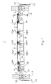
- a guide roller 1, e.g. B. paper guide roller 1 is with their Shaft journal 2; 3 z. B. in camps 4; 6, e.g. B. Ball bearings, each in a side frame 7; 8 are attached.
- the guide roller 1 has one Device for compensating for running disorders from Lanes 9, e.g. B. paper webs. This facility has at least two in the region of the ends 11; 12 of the Guide roller 1 located, changeable in diameter, outer, d. H. Expanding elements 13 close to the shaft journal; 14 on.
- Expanding elements 13; 14 are more of each other and closed the expansion elements 13 near the shaft journal; 14 spaced annular expansion elements 15; 16; 17th arranged (Fig. 1).
- expansion elements 13 to 17 are in the range of Side edges of the web 9 arranged so that the Expanding elements on the entire edge area of the web 9 Act.
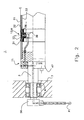
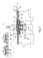
- Each expansion element 13 to 17 consists of an in a first annular groove 19 of a jacket 21, the guide roller 1, d. H. the lateral surface of the guide roller 1 arranged Inner ring 22, which is designed to be permeable to pressure medium is (Fig. 3 and 4) and serves as a support element.
- the Inner ring 22 preferably has two from the outside in the Ring groove 19 insertable half rings made of air-permeable, porous material, e.g. B. sintered bronze. On his Outside 23 is the inner ring 22 with a rubber-elastic material, e.g. B. rubber or elastic Plastic, such as polyurethane existing outer ring 24 covered.
- At least the left and right Edge regions 26; 27 of the outer ring 24 are in one second and third profiled annular groove 28; 29 of Jacket 21 attached, e.g. B. in that Underside of the outer ring 24 near the side edges arranged annular beads 30 in the annular groove 28; 29 intervention.
- These breathable half rings of Inner ring 22 distribute the compressed air evenly below the expansion element 13 to 17. After switching off the Compressed air prevents those that act as support elements Half rings that the web edges the outer ring 24 under one Press level C of the jacket 21 of the guide roller 1. In order to disturbances in the course of the web 9 are avoided.
- the expansion elements 13 to 17 close directly, i. H. almost without interruption to the lateral surface 21 of the Guide roller on.
- the guide roller 1 each has a support ring 36.
- This support ring 36 has an outward, d. H. in Direction of the jacket 21 of the guide roller 1 open Ring groove 37 as a pressure medium distributor, which in turn a number of holes in the jacket 21 38 or Slots are connected to the annular groove 19.
- the support ring 36 is on the jacket 21 opposite side, d. H. its inside with a Pressure fluid connection 39 provided.
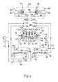
- Each support ring 36 has a pressure medium connection 39, e.g. B. angle tube piece, each of which pneumatic line 41 to 45 with one at the Guide roller 1 located left-hand distributor head 47th or right-hand distributor head 48 is connected.
- a pressure medium connection 39 e.g. B. angle tube piece, each of which pneumatic line 41 to 45 with one at the Guide roller 1 located left-hand distributor head 47th or right-hand distributor head 48 is connected.
- the others Expanding elements 13 to 17 are over Double check valves 49; 51; 52 optionally via the left distributor head 47 or the right distributor head 48 can be supplied with pressure medium.
- the distributor head 47; 48 is no closer about designated lines with a pressure medium distributor 53; 54, a rotary lead-in 56; 57, a pressure regulator, e.g. B. Proportional pressure regulator valve 58; 59 and one Pressure medium accumulator or a port P1; P2 for Pressure fluid accumulator connected.
- pressure indicator 63; 64 can for the actuation of the expansion elements 13 to 17 required pressure of the print medium - e.g. B. Compressed air or oil - be checked.
- each of the Expansion elements 13 to 17 by an expansion element 67 to be replaced (Fig. 6).
- This expansion element 67 consists of an in an annular groove 19 of the jacket 21 Guide roller 1 located, elastic, with a Pressure medium, e.g. B. Compressed air fillable hose 68 elastic material, e.g. B. plastic or rubber.
- the Hose 68 is endless and ring-shaped lies with its lower, d. H. the coat 21 facing side 69 on the bottom surface of an annular groove 19 of the jacket 21 of the guide roller 1.
- the hose 68 has 71 on both sides; 72, d. H. in the left or right edge area 73; 74, e.g. B. from same material existing, ring beads 30, which in second and third ring grooves 28; 29 of the jacket 21 intervene and hold the hose 68 tight.
- the lower side 69 of hose 68 carries at least one Nipple 76 which in a corresponding bore 77 of the engages under the annular groove 19 located jacket 21 and thus an air-permeable connection to the Pressure fluid distributor or the annular groove 37 produces.
- the wall of the hose 68 in below acts here Connection with the support ring 36 as a support element.
- Either the inner ring 22 of the first embodiment as also the lower wall of the hose 68 of the second Embodiment act in conjunction with the Support ring 36 as support elements. Through this Support elements ensures that the expansion elements 14 to 17; 67 in its rest position A from the web 9 not be pressed below level C of the jacket 21.
- the expansion element 67 has A in its rest position a diameter on the same level C with the Coat 21 lies. In working position B increases the diameter of the expansion element 67 accordingly (Fig. 6).
- a setpoint input 78; 79 of Proportional pressure control valve 58; 59 is about one electrical line 83; 84 with setpoint outputs 104; 106 of a proportional controller 88 is connected.
- an actual value output 81; 82 of the Proportional pressure control valve 58; 59 about electrical Lines 86; 87 with an actual value input 107; 108 of Proportional controller 88 in connection.
- the proportional controller 88 is via actual value inputs 109; 111 and electrical lines 85; 89 on Actual value outputs 91; 92 of light barriers 94; 96 one Photoelectric web edge scanner 93 connected.
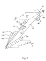
- the light barriers 94; 96 each have a transmitter and a receiver on the side frame fixed Mounts 97; 98 according to the width of the web are adjustable (Fig. 4; Fig. 7).
- the Proportional controller 88 and the light barriers 94; 96 are each with an electrical line 95 to one Not shown voltage source connected.
- the guide roller 1 can, in the running direction E of the web 1 seen that on the light barriers 94; 96 existing Web edge scanning device 93 may be arranged downstream.
- a Hopper feed roller 99 of a folder takes other lanes 101; 102; 103, each over Diameter-variable guide rolls, not shown a longitudinal fold former, also not shown are feedable.
- the guide rollers are at least in one Angle of at least 5 °, preferably more than 30 ° from track 66; 101; 102; 103 entwined.
- a deflection of the path 66 is caused by the light barriers 94; 96 monitors which query the web edges. Becomes an existing balance between the determined Measured values disturbed, d. H. runs the web 66 z. B. after left in the direction of light barrier 94, so there is Proportional controller 88 signals to the left Proportional pressure control valve 58 from.
- the Proportional pressure control valve 58 changes sensitively the air pressure in the expansion element 13, which is a Working position B assumes (Fig. 4). That repeats itself so many times until the balance between those of the Light barriers 94; 96 measured values determined again is made.
- the function of the guide roller 1 with the device for compensating for running disturbances in webs is as follows: The by means of the distribution heads 47; 48 preselected expansion elements, e.g. B. the respective outer expansion elements 13; 14 (Fig. 5) for widening the edges of a full-width web 66 z. B. supplied with compressed air.
- the compressed air comes from the compressed air storage port P1; P2 via the proportional pressure control valve 58; 59 and the rotary inlet 56; 57 in the pressure medium distributor 53; 54.
- the pressure medium distributor 53 is on the left Distributor head 47 connected for compressed air.
- the left one Distribution head 47 is in the selection position I and is thus via the pneumatic line 41 with the left outer expansion element 13 connected, which fills is and occupies a working position B (Fig. 5).
- the pressure medium distributor 54 is on the right Distributor head 48 connected.
- the right header 48 is also in selection position I and is therefore over the pneumatic line 42 with the right outer Expanding element 14 in connection.
- the expanding elements 13; 14 - see Fig. 3 using the example Expanding element 16 - are each over the Pressure medium connection 39 and the annular groove 37, the bores 38, the air-permeable ring 22 filled with compressed air, which in the space between the outer ring 24 and the air-permeable ring 22 arrives so that this filled with air occupies a working position B.
- the Working position B are the expansion elements 13; 14 in such a position in which the outside 31 of the enlarged outer ring 24 or after the other embodiment, the outside 31 of diameter-enlarged hose 68 outside the Level C of the guide roller 1 is.
- the path lies 9; 66 both on the expansion elements 13; 14 or 13; 15 as well as on the between the expansion elements 13; 14 or 13; 15 lying surface 21 of the guide roller 1.
- the outer ring 24 made of elastic material or the hose 68 can have other properties have such.
- Such properties can in the first case, for. B. by adding Teflon and in the second case by an addition of quartz sand or corundum can be achieved.
Landscapes
- Registering, Tensioning, Guiding Webs, And Rollers Therefor (AREA)
- Replacement Of Web Rolls (AREA)
Claims (9)
- Rouleau-guide comportant un dispositif pour compenser des perturbations du défilement dans le cas de bandes (9; 66), avec au moins deux éléments d'élargissement (13 à 17; 67) actionnés par un fluide sous pression, à diamètre modifiable, caractérisé en ce que les éléments d'élargissement (13 à 17; 67) sont disposés dans la zone des bords latéraux de la bande (9; 66) et sans interruption sur une surface d'enveloppe (21) du rouleau de guidage (1), en ce qu'au moins deux éléments d'élargissement (13 à 17; 67) sont sollicités par une pression de base, de manièe que leur rayon soit supérieur à un ryon de la surface d'enveloppe (21) du rouleau de guidage (1), entre les deux éléments d'élargissement (13 à 17; 67), et en ce qu'une deuxième pression est susceptible d'être superposée à la pression de base d'au moins un élément d'élargissement (13 à 17; 67).
- Rouleau-guide selon la revendication 1, caractérisé en ce qu'au moins trois éléments d'élargissement (13 à 17; 67) sont disposés et en ce que, pour assurer le guidage d'une bande de demi-largeur (9; 66), le troisième élément d'élargissement (15) est disposé centralement par rapport aux deux autres éléments d'élargissement (13; 14).
- Rouleau-guide selon la revendication 1, caractérisé en ce qu'au moins cinq éléments d'élargissement (13; 14; 67), présentant à peu prés le même espacement en direction radiale sont disposés pour assurer le guidage d'une bande (9; 66) de quart ou de trois quarts de largeur;
- Rouleau-guide selon la revendication 1, caractérisé en ce que les éléments d'élargissement (13 à 17; 67) sont actionnables indépendamment les uns des autres.
- Rouleau-guide selon la revendication 1, caractérisé en ce qu'une bague extérieure (24) des éléments d'élargissement (13 à 17; 67) est constituée d'un matériau ayant l'élasticité du caoutchouc.
- Rouleau-guide selon la revendication 1, caractérisé en ce que, en au moins un état de fonctionnement, des éléments d'appui (36) sont disposés en agissant sur une surface intérieure des éléments d'élargissement (13 à 17; 67).
- Rouleau-guide selon la revendication 1, caractérisé en ce que les éléments d'élargissement (13 à 17; 67) sont reliés à un dispositif de détection de bord de bande (93) photoélectrique, par l'intermédiaire de soupapes de régulation de pression à caractéristique proportionnelle (58; 59) électro-pneumatique et d'un régulateur proportionnel (88) électro-pneumatique.
- Rouleau-guide selon la revendication 7, caractérisé en ce que le dispositif de détection de bord de bande (93) présente chaque fois une barrière photoélectrique (94; 96).
- Rouleau-guide selon la revendication 1, caractérisé en ce que le rouleau-guide (1) et disposé directement avant un rouleau d'introduction en cône d'un appareil de pliage.
Applications Claiming Priority (5)
| Application Number | Priority Date | Filing Date | Title |
|---|---|---|---|
| DE19805215 | 1998-02-10 | ||
| DE1998105215 DE19805215A1 (de) | 1998-02-10 | 1998-02-10 | Einrichtung zum Kompensieren von Laufstörungen bei Papierbahnen |
| DE1998105214 DE19805214A1 (de) | 1998-02-10 | 1998-02-10 | Einrichtung zur Korrektur der Seitenlage einer Papierbahn |
| DE19805214 | 1998-02-10 | ||
| PCT/DE1999/000347 WO1999040005A1 (fr) | 1998-02-10 | 1999-02-10 | Rouleau-guide |
Publications (2)
| Publication Number | Publication Date |
|---|---|
| EP1053200A1 EP1053200A1 (fr) | 2000-11-22 |
| EP1053200B1 true EP1053200B1 (fr) | 2001-11-28 |
Family
ID=26043740
Family Applications (2)
| Application Number | Title | Priority Date | Filing Date |
|---|---|---|---|
| EP99915467A Expired - Lifetime EP1053200B1 (fr) | 1998-02-10 | 1999-02-10 | Rouleau-guide |
| EP99915468A Expired - Lifetime EP1056671B1 (fr) | 1998-02-10 | 1999-02-10 | Rouleau-guide |
Family Applications After (1)
| Application Number | Title | Priority Date | Filing Date |
|---|---|---|---|
| EP99915468A Expired - Lifetime EP1056671B1 (fr) | 1998-02-10 | 1999-02-10 | Rouleau-guide |
Country Status (3)
| Country | Link |
|---|---|
| EP (2) | EP1053200B1 (fr) |
| DE (2) | DE59900464D1 (fr) |
| WO (2) | WO1999040005A1 (fr) |
Families Citing this family (5)
| Publication number | Priority date | Publication date | Assignee | Title |
|---|---|---|---|---|
| DE19955099B4 (de) | 1999-11-16 | 2010-02-11 | Maschinenfabrik Wifag | Rotationskörpergebilde für eine Bahnbreitenkorrektur |
| DE10215938C1 (de) * | 2002-04-11 | 2003-09-04 | Koenig & Bauer Ag | Zugvorrichtung für eine Materialbahn |
| DE10340569A1 (de) * | 2003-09-01 | 2005-04-07 | Koenig & Bauer Ag | Verfahren zur Reduktion von Passerfehlern auf einer in einer bahnverarbeitenden Vorrichtung und ein Druckwerk |
| DE102009000353B4 (de) | 2009-01-21 | 2016-04-28 | Koenig & Bauer Ag | Zugwalze |
| CN118458465B (zh) * | 2024-07-12 | 2024-09-20 | 徐州创新包装新材料有限公司 | 一种编织袋生产用输送纠偏装置及纠偏控制方法 |
Family Cites Families (4)
| Publication number | Priority date | Publication date | Assignee | Title |
|---|---|---|---|---|
| GB1066423A (en) * | 1965-04-28 | 1967-04-26 | Mount Hope Machinery Ltd | Fluid bearing table roll |
| US3726588A (en) * | 1971-12-30 | 1973-04-10 | Xerox Corp | Web tracking system |
| CH662619A5 (de) * | 1983-09-28 | 1987-10-15 | Escher Wyss Ag | Durchbiegungseinstellwalze. |
| DE9211162U1 (de) * | 1992-08-20 | 1994-01-27 | Eduard Küsters Maschinenfabrik GmbH & Co KG, 47805 Krefeld | Walze |
-
1999
- 1999-02-10 EP EP99915467A patent/EP1053200B1/fr not_active Expired - Lifetime
- 1999-02-10 DE DE59900464T patent/DE59900464D1/de not_active Expired - Fee Related
- 1999-02-10 WO PCT/DE1999/000347 patent/WO1999040005A1/fr not_active Ceased
- 1999-02-10 WO PCT/DE1999/000348 patent/WO1999040006A1/fr not_active Ceased
- 1999-02-10 EP EP99915468A patent/EP1056671B1/fr not_active Expired - Lifetime
- 1999-02-10 DE DE59900466T patent/DE59900466D1/de not_active Expired - Fee Related
Also Published As
| Publication number | Publication date |
|---|---|
| WO1999040005A1 (fr) | 1999-08-12 |
| WO1999040006A1 (fr) | 1999-08-12 |
| DE59900464D1 (de) | 2002-01-10 |
| EP1056671B1 (fr) | 2001-11-28 |
| DE59900466D1 (de) | 2002-01-10 |
| EP1056671A1 (fr) | 2000-12-06 |
| EP1053200A1 (fr) | 2000-11-22 |
Similar Documents
| Publication | Publication Date | Title |
|---|---|---|
| EP1106554B1 (fr) | Plieuse mobile et arrangement de triangle plieur | |
| DE4033642A1 (de) | Leitvorrichtung zum fuehren, aus- und/oder umlenken einer materialbahn | |
| DE3630570C2 (de) | Verfahren und Vorrichtung in einem Papiermaschinen-Zylindertrockner mit Zweisiebführung | |
| EP1101721B1 (fr) | Corps rotatif pour la correction de la largeur d'une bande | |
| WO1992013787A1 (fr) | Dispositif d'enroulement d'une bande de film en matiere plastique | |
| EP1112951B1 (fr) | Dispositif de guidage sans contact d'une bande de matériau | |
| EP0857821A2 (fr) | Dispositif d'aspiration | |
| EP1056671B1 (fr) | Rouleau-guide | |
| DE4026021C2 (de) | Pressenpartie einer Papiermaschine | |
| DE1574418B1 (de) | Fuehrungsvorrichtung fuer laufende Materialbahnen | |
| EP1591392B1 (fr) | Aménagement de rouleaux élargisseurs pour un guidage de bandes sans plis | |
| DE4416289C2 (de) | Vorrichtung zum Fördern eines geschuppten Bogenstromes | |
| DE19502240C2 (de) | Verfahren und Vorrichtung zum Einziehen einer Bedruckstoffbahn im Rollenrotationsdruck | |
| DE10337248A1 (de) | Bahnspreizverfahren und Bahnspreizvorrichtung | |
| WO2000059811A1 (fr) | Mecanisme d'aiguillage pour systeme de transport, notamment pour transporteur a rouleaux | |
| DE202018101098U1 (de) | Bahnleitvorrichtung | |
| EP1941096A1 (fr) | Rouleau deplisseur | |
| EP1788153A2 (fr) | Dispositif pour le traitement d'une bande de matériau | |
| EP2138436B1 (fr) | Dispositif de centrage, de déplissage et/ou d'alignement d'une bande de marchandises déplacée et procédé correspondant | |
| EP0936164B1 (fr) | Vanne à roue cellulaire avec palier additionel | |
| WO2004085155A1 (fr) | Cylindre et dispositif de guidage d'une bande de materiau | |
| DE3806466C2 (fr) | ||
| EP1492719B1 (fr) | Dispositif de traction pour bande de materiau | |
| DE19805214A1 (de) | Einrichtung zur Korrektur der Seitenlage einer Papierbahn | |
| DE2018608C3 (de) | Vorrichtung zur Steuerung der Kantenlage einer bewegten Material bahn |
Legal Events
| Date | Code | Title | Description |
|---|---|---|---|
| PUAI | Public reference made under article 153(3) epc to a published international application that has entered the european phase |
Free format text: ORIGINAL CODE: 0009012 |
|
| 17P | Request for examination filed |
Effective date: 20000831 |
|
| AK | Designated contracting states |
Kind code of ref document: A1 Designated state(s): CH DE FR LI |
|
| GRAG | Despatch of communication of intention to grant |
Free format text: ORIGINAL CODE: EPIDOS AGRA |
|
| GRAG | Despatch of communication of intention to grant |
Free format text: ORIGINAL CODE: EPIDOS AGRA |
|
| GRAH | Despatch of communication of intention to grant a patent |
Free format text: ORIGINAL CODE: EPIDOS IGRA |
|
| 17Q | First examination report despatched |
Effective date: 20010328 |
|
| GRAH | Despatch of communication of intention to grant a patent |
Free format text: ORIGINAL CODE: EPIDOS IGRA |
|
| GRAA | (expected) grant |
Free format text: ORIGINAL CODE: 0009210 |
|
| AK | Designated contracting states |
Kind code of ref document: B1 Designated state(s): CH DE FR LI |
|
| REG | Reference to a national code |
Ref country code: CH Ref legal event code: EP |
|
| REF | Corresponds to: |
Ref document number: 59900464 Country of ref document: DE Date of ref document: 20020110 |
|
| ET | Fr: translation filed | ||
| PLBE | No opposition filed within time limit |
Free format text: ORIGINAL CODE: 0009261 |
|
| STAA | Information on the status of an ep patent application or granted ep patent |
Free format text: STATUS: NO OPPOSITION FILED WITHIN TIME LIMIT |
|
| 26N | No opposition filed | ||
| PGFP | Annual fee paid to national office [announced via postgrant information from national office to epo] |
Ref country code: CH Payment date: 20070213 Year of fee payment: 9 |
|
| PGFP | Annual fee paid to national office [announced via postgrant information from national office to epo] |
Ref country code: DE Payment date: 20070329 Year of fee payment: 9 |
|
| PGFP | Annual fee paid to national office [announced via postgrant information from national office to epo] |
Ref country code: FR Payment date: 20070209 Year of fee payment: 9 |
|
| REG | Reference to a national code |
Ref country code: CH Ref legal event code: PL |
|
| PG25 | Lapsed in a contracting state [announced via postgrant information from national office to epo] |
Ref country code: LI Free format text: LAPSE BECAUSE OF NON-PAYMENT OF DUE FEES Effective date: 20080229 Ref country code: CH Free format text: LAPSE BECAUSE OF NON-PAYMENT OF DUE FEES Effective date: 20080229 |
|
| REG | Reference to a national code |
Ref country code: FR Ref legal event code: ST Effective date: 20081031 |
|
| PG25 | Lapsed in a contracting state [announced via postgrant information from national office to epo] |
Ref country code: DE Free format text: LAPSE BECAUSE OF NON-PAYMENT OF DUE FEES Effective date: 20080902 |
|
| PG25 | Lapsed in a contracting state [announced via postgrant information from national office to epo] |
Ref country code: FR Free format text: LAPSE BECAUSE OF NON-PAYMENT OF DUE FEES Effective date: 20080229 |