EP1053573B1 - Elektrischer sockelkontakt, insbesondere für explosive atmosphäre, und dessen herstellungsverfahren - Google Patents
Elektrischer sockelkontakt, insbesondere für explosive atmosphäre, und dessen herstellungsverfahren Download PDFInfo
- Publication number
- EP1053573B1 EP1053573B1 EP99956088A EP99956088A EP1053573B1 EP 1053573 B1 EP1053573 B1 EP 1053573B1 EP 99956088 A EP99956088 A EP 99956088A EP 99956088 A EP99956088 A EP 99956088A EP 1053573 B1 EP1053573 B1 EP 1053573B1
- Authority
- EP
- European Patent Office
- Prior art keywords
- insulating block
- disc
- contact
- connecting socket
- socket according
- Prior art date
- Legal status (The legal status is an assumption and is not a legal conclusion. Google has not performed a legal analysis and makes no representation as to the accuracy of the status listed.)
- Expired - Lifetime
Links
Images


Classifications
-
- H—ELECTRICITY
- H01—ELECTRIC ELEMENTS
- H01R—ELECTRICALLY-CONDUCTIVE CONNECTIONS; STRUCTURAL ASSOCIATIONS OF A PLURALITY OF MUTUALLY-INSULATED ELECTRICAL CONNECTING ELEMENTS; COUPLING DEVICES; CURRENT COLLECTORS
- H01R13/00—Details of coupling devices of the kinds covered by groups H01R12/70 or H01R24/00 - H01R33/00
- H01R13/44—Means for preventing access to live contacts
- H01R13/447—Shutter or cover plate
- H01R13/453—Shutter or cover plate opened by engagement of counterpart
- H01R13/4532—Rotating shutter
-
- H—ELECTRICITY
- H01—ELECTRIC ELEMENTS
- H01R—ELECTRICALLY-CONDUCTIVE CONNECTIONS; STRUCTURAL ASSOCIATIONS OF A PLURALITY OF MUTUALLY-INSULATED ELECTRICAL CONNECTING ELEMENTS; COUPLING DEVICES; CURRENT COLLECTORS
- H01R13/00—Details of coupling devices of the kinds covered by groups H01R12/70 or H01R24/00 - H01R33/00
- H01R13/46—Bases; Cases
- H01R13/52—Dustproof, splashproof, drip-proof, waterproof, or flameproof cases
- H01R13/527—Flameproof cases
Definitions
- the invention relates to an electrical connection base, particularly for an atmosphere explosive or explosive, in the form of, for example, a socket current or a mobile extension socket, and its manufacturing method.
- connection base as described in document GB-2125234 A, which, to protect the contacts of the base in the absence of any connection with a plug, is equipped with a safety disk provided with as many peripheral openings that the insulating block of the base is provided with peripheral contact housings, and which is rotatably mounted on said insulating block by a central opening with which it is provided and whose inner surface cooperates with the lateral surface of a central protuberance of the block insulation forming a rotation hub, so that the peripheral openings of the discs can be brought to will by rotation of the latter in relation to housing corresponding insulating block.
- this part is vulnerable and the slightest deterioration can the effectiveness of said explosion-proof joint surface.
- connection base provided with of a security disk as mentioned above, but which is particularly remarkable in that at least some of the surfaces in contact of the safety disc and the insulating block as well as the respectively internal surfaces of at least the peripheral openings of the safety disc and outer corresponding pins of the plug form explosion-proof joint surfaces so that at least the peripheral dwellings contact of the insulating block constitute at least one explosion-proof envelope.
- the central protuberance or hub of the insulating block may be in a embodiment, pierced for the passage of a central pin of the plug for cooperate with a contact arranged in a central housing of the insulating block.
- the safety disc and the insulating block have surfaces planar frontal surfaces which apply to each other and at least a part of which an explosion-proof joint surface and / or explosion-proof joint surfaces between the safety disc and the insulating block consist at least in part of the least part of the lateral surface of rotation of the hub of the insulating block and the surface inside the central opening of the disc.
- the security disk has an extension peripheral ring which covers a part of the insulating block, at least a part of the overlapping zones of said insulating block and said extension constituting lateral rotational surfaces forming an explosion-proof joint.
- the lateral surfaces of rotation of the insulating block and the safety disk formed on the one hand by the hub and the a journey disk and, on the other hand, by the overlapping zones of the insulating block and the extension of the disc are cylindrical surfaces of revolution.
- At least the peripheral units of contact are, for example, closed at the base of the corresponding contacts by elements forming in said housing explosion-proof joint surfaces.
- the hub of the insulating block has a flared end in hollow which ensures the translation in solidarity of the disk and the insulating block.
- the contacts of the base are end pressure contacts each provided with a contact head, a braid and a helical spring disposed in the corresponding contact housing.
- the invention further suggests a particular non-compulsory molding method, which is remarkable in that the insulating block is overmoulded in or on the disk of safety, itself realized previously and serving as insert, the withdrawal of the material the block after molding ensuring the gap, or play, necessary and adjusted between surfaces in contact with the parts for the rotation of the disk on said block and for constituting the explosion-proof joint (s).
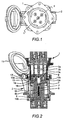
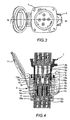
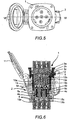
- the electric socket shown therefore comprises a plug 1 and a base 2.
- Plug 1 is provided with contact pins such as pins 3a, 3b, 3c visible on the sectional views, and the base 2 has antagonistic contacts 4a, 4b, 4c.
- Contacts 4a, 4b, 4c of the base are arranged in housings 5a, 5b, 5c formed in an insulating block 6 and they are here as a non-limiting example under form of end pressure contacts, generally constituted each classically and as represented by a contact head 7, a conductive braid 7 'and a spring helicoidal pressure 8 (references 7, 7 'and 8 being listed only in Figure 2 for the central contact 4b).
- the plug 1 here has five pins and of course there are so many antagonistic contacts in the base 2 but we can not see only three in Figures 4 and 6 and one in Figure 2.
- the base 2 is provided with a central housing 5b for a central contact 4b constituting the earth contact intended to cooperate with a central contact pin 3b of the plug, the other contacts 4a, 4c, 3a, 3c of the base and the plug being called peripheral and constituting the phase contacts or the neutral.
- the base is provided with a disc 9 rotatably mounted on the insulating block 6, the disc 9 being provided with as much 10a, 10b 10c that the plug and the base are provided with contacts since said openings are intended to be traversed by the contact pins of the plug as it will be described below.
- the base is provided with a cover of protection 11 intended to be folded when the plug is not connected, and a hook 12 (FIGS. 4 and 6) to lock either the cover or the plug in the base in connection position ( Figures 5 and 6).
- the insulating block 6 is provided with a central protrusion 13 pierced in its center, which forms a rotation hub for the safety disc 9 which cooperates with said hub by the inner surface of its central opening 10b.
- Said central opening 10b of the disk 9 and the central protuberance or hub 13 of the insulating block 6 constitute lateral surfaces of rotation which are, in addition, as shown in this example, at least partly cylindrical of revolution.
- the safety disk 9 is more provided with a peripheral annular extension 14 which covers a part of the insulating block 6, the overlapping zones of the extension 14 and the insulating block 6 constituting cylindrical rotating surfaces of revolution, coaxial with surfaces mentioned above.
- the security disk 9 hides the peripheral contacts 4a, 4c of the base 2, while the pins 3a, 3b, 3c of the plug may be introduced into openings 10a, 10b 10c of the safety disk (FIGS. and 2).
- the plug is rotated which causes the rotation of the security disk until it discovers the peripheral contacts 4a and 4c of the base (FIGS. and 4).
- the protrusion 13 of the insulating block 6 is further provided here with a portion flared hollow 13 '( Figure 1) which secures in translation the safety disc 9 and said insulating block 6, said portion 13 'may also have slots (clearly visible Figure 10) creating sectors that provide flexibility.
- the protuberance 13 does not does not present the flared portion 13 ', the fixing of the disc 9 being provided by a clip reported.
- the inner surface of the aperture 10b of the disk and the surface the outer surface of the hub 13 constitute lateral surfaces of rotation on a certain length, as well as the overlapping areas of the extension 14 of the disc on block 6, while the peripheral pins 3a, 3c of the plug pass through a certain length the calibrated openings 10a, 10c of the disc 9.
- the contact housing 5a, 5c (and even here 5b) are closed to their ends opposite the contact heads by any means and in particular by means of elements constituting the crimping feet of the base contacts as shown in 15a, 15b and 15c.
- these elements form in said dwellings 15a, 15b, 15c of the explosion-proof joint surfaces.
- the French and European standards define an explosion-proof envelope as a mode of protection in which parts that can ignite an explosive atmosphere are enclosed in an envelope which resists the pressure developed during an internal explosion of a mixture explosive and which prevents the transmission of the explosion to the surrounding explosive atmosphere of the envelope.
- An explosion-proof joint is where the corresponding surfaces of two elements of an envelope or the common part of envelopes come together and prevent the transmission of an internal explosion to the surrounding explosive atmosphere of the envelope, its length being the shortest path between the inside and the outside of the envelope.
- the gap of an explosion-proof joint is of course the gap between the faces of said seal.
- the gap is the difference between the diameter of the bore and the body cylindrical.
- the base according to the invention can therefore be explosion-proof because of the constitution a common flameproof enclosure for all peripheral contacts by simple constitution of explosion-proof joints.
- the example shown relates to a base and a connection plug for a three-phase current
- the invention also plans to build an explosion-proof flat gasket between the insulation block 6 and the disc 9.
- the insulating block 6 and the disc 9 have flat frontal surfaces that apply to one another.
- the gap between said surfaces combined with the distance between two peripheral housings or equivalently between two peripheral openings 10a, 10c of the safety disk, such as the distance diagrammatically shown in d in FIG. 9, makes it possible to constitute, if desired, a explosion-proof flat gasket referenced 16 in the sectional figures, which can thus create an explosion-proof envelope for each peripheral housing 5b, 5c of contact so that the absence of certain pins and thus openings of the disk unsealed is not detrimental.
- the embodiment described above has two cylindrical seals explosion-proof (hub 13 and extension 14), in addition to those made by the pins themselves, and possibly an explosion-proof flat gasket 16 which makes it possible to carry out an explosion-proof enclosure for each peripheral electrical contact:
- the explosion-proof flat gasket 16 made then makes it possible not to be in the obligation to have an explosion-proof cylindrical seal formed by said protuberance.
- the invention also proposes, without this being mandatory, an original process molding.
- the disk is first made which can be seen in FIGS. 2, 4, 6 and more particularly on the Figures 9 and 10, for example by molding, in particular in a thermosetting material.
- FIG. 9 represents the safety disc 9, actually in the form of a cap because of its peripheral annular extension 14, FIG. result obtained from block 6 and disk 9 after overmolding, or after assembly of molded parts separately.
Landscapes
- Connector Housings Or Holding Contact Members (AREA)
Claims (10)
- Elektrische Anschluss-Steckdose (2), insbesondere für eine explosible Atmosphäre, die mit elektrischen Kontakten (4a,4c) versehenn ist, die in Kontakt-Umfangsausnehmungen (5a, 5c) eines Isolierblockes (6) angebracht und für das Zusammenwirken mit entsprechenden Kontaktstiften (3a, 3c) eines Steckers vorgesehen sind, während eine Sicherheitsscheibe (9), welche mit wenigstens genauso viel Umfangsdurchbrechungen (10a, 10c) wie der Isolierblock (6) mit Kontakt-Umfangsausnehmungen (5a, 5c) versehen ist, rotierbar an dem vorerwähnten Isolierblock mittels einer an ihr vorhandenen zentralen Durchbrechung (10b) angebracht ist, wobei deren Innenfläche mit der lateralen Fläche eines zentralen Fortsatzes (13) des Isolierblockes (6) zusammenwirkt und der Fortsatz eine Rotationsnabe bildet derart, dass die Umfangsdurchbrechungen (10a, 10c) nach Wunsch mittels Rotation der letzteren in Bezug auf die entsprechenden Ausnehmungen (5a, 5c) des Isolierblockes (6) eingestellt werden können, dadurch gekennzeichnet, dass wenigstens einige der einander berührenden Flächen der Sicherheitsscheibe (9) und des Isolierblockes (6) so wie die inneren Flächen wenigstens der Umfangsdurchbrechungen (10a, 10c) der Sicherheitsscheibe (9) bzw. die äusseren Flächen der entsprechenden Kontaktstifte (3a, 3c) des Steckers Flächen der explosionsgeschützten Verbindungsstelle bilden derart, dass wenigstens die Kontakt-Umfangsausnehmungen (5a, 5c) des Isolierblockes wenigstens ein explosionsgeschütztes Gehäuse bilden.
- Anschluss-Steckdose nach Anspruch 1, dadurch gekennzeichnet, dass der zentrale Fortsatz bzw. die Nabe (13) des Isolierblockes durchbrochen ist für den Durchgang eines zentralen Kontaktstiftes (3b) des Steckers, der in der Lage ist, mit einem Kontakt (4b), welcher in einer zentralen Ausnehmung (5b) des Isolierblockes (6) angeordnet ist, zusammen zu wirken.
- Anschluss-Steckdose nach den Ansprüchen 1 und 2, dadurch gekennzeichnet, dass die Sicherheitsscheibe (9) und der Isolierblock (6) mit ebenen Stirnflächen versehen sind, die an einander anliegen und von denen wenigstens ein Teil eine Fläche der explosionsgeschützten Verbindungsstelle (16) bildet.
- Anschluss-Steckdose nach einem der Ansprüche 1 - 3, dadurch gekennzeichnet, dass die Flächen der explosionsgeschützten Verbindungsstelle zwischen der Sicherheitsscheibe (9) und dem Isolierblock (6) wenigstens teilweise durch wenigstens einen Teil der seitlichen Rotationsfläche der Nabe (13) des Isolierblockes (6) und der inneren Fläche der zentralen Durchbrechung (10b) der Scheibe gebildet sind.
- Anschluss-Steckdose nach einem der Ansprüche 1 - 4, dadurch gekennzeichnet, dass die Sicherheitsscheibe (9) eine ringförmige Umfangsverlängerung (14) aufweist, welche einen Teil des Isolierblockes (6) überdeckt, wobei wenigstens ein Teil der überdeckten Bereiche des vorerwähnten Isolierblockes (6) und der vorerwähnten Verlängerung (14) seitliche Rotationsflächen darstellen, welche eine explosionsgeschützte Verbindungsstelle bilden.
- Anschluss-Steckdose nach Anspruch 5, dadurch gekennzeichnet, dass die seitlichen Rotationsflächen des Isolierblockes (6) und der Sicherheitsscheibe (9), die einerseits durch die Nabe (13) und die zentrale Durchbrechung (10b) der Scheibe und andererseits durch die abgedeckten Bereiche des Isolierblockes (6) und der Verlängerung (14) der Scheibe gebildet werden, zylindrische Rotationsflächen sind.
- Anschluss-Steckdose nach einem der Ansprüche 1 - 6, dadurch gekennzeichnet, dass wenigstens die Umfangsausnehmungen (5a, 5c) an der Unterseite der entsprechenden Kontakte (4a, 4c) durch Elemente (15a, 15c) geschlossen sind, welche in den vorerwähnten Ausnehmungen explosionsgeschützte Verbindungsstellen-Flächen bilden.
- Anschluss-Steckdose gemäss einem der Ansprüche 1 - 7, dadurch gekennzeichnet, dass die Nabe (13) des Isolierblockes (6) ein äusserstes Ende (13') aufweist, welches sich konisch erweitert und hohl ist und eine Sicherheit gegen Verschiebung der Scheibe (9) und des Isolierblockes (6) gewährleistet.
- Anschluss-Steckdose gemäss einem der Ansprüche 1 - 8, dadurch gekennzeichnet, dass die Kontakte (4a, 4b, 4c) der Steckdose als End-Druckkontakte ausgebildet sind, von denen jeder mit einem Kontaktkopf (7), einer Litze (7')und einer Schraubenfeder (8) versehen ist, die in der jeweiligen Ausnehmung (5a, 5b, 5c) für den Kontakt angeordnet sind.
- Elektrische Anschluss-Steckdose gemäss einem der Ansprüche 1 - 9, dadurch gekennzeichnet, dass der Isolierblock (6) in oder auf der Sicherheitsscheibe (9) geformt wird, die selbst vorher hergestellt worden ist und als Einsatz dient, wobei das Schwinden des Materials des Blockes (6) nach der Formung den kleinen Zwischenraum oder das Spiel gewährleistet, welcher bzw. welches zwischen den in Kontakt befindlichen Flächen der Teile für die Rotation der Scheibe (9) auf dem vorerwähnten Block (6) und zur Bildung der explosionsgesicherten Verbindungsstelle(n) erforderlich und eingestellt ist.
Applications Claiming Priority (3)
| Application Number | Priority Date | Filing Date | Title |
|---|---|---|---|
| FR9815329A FR2786932B1 (fr) | 1998-12-04 | 1998-12-04 | Socle de connexion electrique, notamment pour atmosphere explosible, et son procede de fabrication |
| FR9815329 | 1998-12-04 | ||
| PCT/FR1999/002844 WO2000035054A1 (fr) | 1998-12-04 | 1999-11-19 | Socle de connexion electrique, notamment pour atmosphere explosible, et son procede de fabrication |
Publications (2)
| Publication Number | Publication Date |
|---|---|
| EP1053573A1 EP1053573A1 (de) | 2000-11-22 |
| EP1053573B1 true EP1053573B1 (de) | 2004-12-15 |
Family
ID=9533585
Family Applications (1)
| Application Number | Title | Priority Date | Filing Date |
|---|---|---|---|
| EP99956088A Expired - Lifetime EP1053573B1 (de) | 1998-12-04 | 1999-11-19 | Elektrischer sockelkontakt, insbesondere für explosive atmosphäre, und dessen herstellungsverfahren |
Country Status (5)
| Country | Link |
|---|---|
| EP (1) | EP1053573B1 (de) |
| AU (1) | AU753861B2 (de) |
| DE (1) | DE69922636T2 (de) |
| FR (1) | FR2786932B1 (de) |
| WO (1) | WO2000035054A1 (de) |
Families Citing this family (1)
| Publication number | Priority date | Publication date | Assignee | Title |
|---|---|---|---|---|
| GB0208954D0 (en) * | 2002-04-19 | 2002-05-29 | Hawke Cable Glands Ltd | An electrical connector |
Family Cites Families (5)
| Publication number | Priority date | Publication date | Assignee | Title |
|---|---|---|---|---|
| US2697212A (en) * | 1953-01-12 | 1954-12-14 | Sarl Arlux | Explosion-proof electrical connecting device |
| FR1301448A (fr) * | 1961-07-08 | 1962-08-17 | Expl Des Procedes Marechal D | Perfectionnements aux dispositifs de connexions électriques |
| US3330920A (en) * | 1965-12-02 | 1967-07-11 | Arthur I Appleton | Explosion-proof plug and receptacle with switch means |
| DE3221111C2 (de) * | 1982-06-04 | 1986-01-02 | Brown, Boveri & Cie Ag, 6800 Mannheim | Explosions- oder schlagwettergeschützte elektrische Kupplungssteckvorrichtung |
| FR2686461A1 (fr) * | 1992-01-16 | 1993-07-23 | Besso Rene | Dispositif de raccordement electrique etanche. |
-
1998
- 1998-12-04 FR FR9815329A patent/FR2786932B1/fr not_active Expired - Fee Related
-
1999
- 1999-11-19 DE DE69922636T patent/DE69922636T2/de not_active Expired - Lifetime
- 1999-11-19 EP EP99956088A patent/EP1053573B1/de not_active Expired - Lifetime
- 1999-11-19 AU AU12774/00A patent/AU753861B2/en not_active Expired
- 1999-11-19 WO PCT/FR1999/002844 patent/WO2000035054A1/fr not_active Ceased
Also Published As
| Publication number | Publication date |
|---|---|
| EP1053573A1 (de) | 2000-11-22 |
| FR2786932B1 (fr) | 2000-12-29 |
| AU1277400A (en) | 2000-06-26 |
| DE69922636T2 (de) | 2005-05-25 |
| FR2786932A1 (fr) | 2000-06-09 |
| DE69922636D1 (de) | 2005-01-20 |
| WO2000035054A1 (fr) | 2000-06-15 |
| AU753861B2 (en) | 2002-10-31 |
Similar Documents
| Publication | Publication Date | Title |
|---|---|---|
| EP0464767B1 (de) | Aus zwei über ein Gelenk und elektrisch verbundenen Elementen bestehendes Gerät | |
| EP0528735B1 (de) | Selektive Vorrichtung für elektrische Verbindung, welche mit einer Sicherheitsscheibe und einer komplementären Scheibe ausgerüstet ist | |
| WO1989001248A1 (fr) | Connecteur a semelle retractable prevu pour la protection des sorties de contact | |
| FR2680434A1 (fr) | Joint d'etancheite, notamment d'etancheite electromagnetique. | |
| US6382990B1 (en) | Electric connection base plate in particular for explosible environment and method for making same | |
| FR2703841A1 (fr) | Connecteur électrique pourvu d'une pluralité de modules de connexion. | |
| EP1102362B1 (de) | Elektrische Steckdose mit Dichtungsbalg | |
| EP1053573B1 (de) | Elektrischer sockelkontakt, insbesondere für explosive atmosphäre, und dessen herstellungsverfahren | |
| FR3025947A1 (fr) | Corps isolant pour connecteur debrochable | |
| EP0606181B1 (de) | Transformator, insbesondere Messwandler, zum Beispiel zur Erkennung von Fehlern in elektrischen Kabeln | |
| EP0091867B1 (de) | Elektrische Verbindereinrichtung mit einem abnehmbaren modulartigen kapazitiven Filtergehäuse | |
| FR2523366A1 (fr) | Support de fusible | |
| EP1139060B1 (de) | Pyrotechnischer Zünder mit einem elektrischen oder elektronischen Bauelement und/oder mit einem Steckverbinder | |
| EP2456014B1 (de) | Verbindungsklemme zwischen einer elektrischen umlaufenden Maschine eines Kraftfahrzeugs und einem Stromkreiskabel des besagten Fahrzeugs | |
| EP0891627B1 (de) | Modulare elektrische schalteranordung | |
| FR2797353A1 (fr) | Connecteur electrique utlisant des organes penetrant dans l'isolation | |
| FR2898735A1 (fr) | Element de connexion electrique etanche | |
| EP0530076B1 (de) | Abgeschirmter elektrischer Verbinder | |
| FR2783099A1 (fr) | Ensemble de connexion hermetique | |
| FR2679378A1 (fr) | Fusible electrique pour courants forts. | |
| EP2176475B9 (de) | Verfahren zur herstellung eines stators für ein drehendes kraftfahrzeugschloss und schlossstator | |
| EP0669696A1 (de) | Modulare Speise- und Steuereinheit für einen Wechselstromgenerator eines Fahrzeugs | |
| MXPA00007159A (en) | Electric connection base plate in particular for explosible environment and method for making same | |
| EP0768691B1 (de) | Elektrischer Drehschalter mit Mehrstellung für Diebstahlschutz für Kraftfahrzeuge | |
| FR3146036A1 (fr) | Dispositif de protection contre les surtensions |
Legal Events
| Date | Code | Title | Description |
|---|---|---|---|
| PUAI | Public reference made under article 153(3) epc to a published international application that has entered the european phase |
Free format text: ORIGINAL CODE: 0009012 |
|
| AK | Designated contracting states |
Kind code of ref document: A1 Designated state(s): AT BE CH CY DE DK ES FI FR GB GR IE IT LI LU MC NL PT SE |
|
| 17P | Request for examination filed |
Effective date: 20001114 |
|
| 17Q | First examination report despatched |
Effective date: 20031009 |
|
| RBV | Designated contracting states (corrected) |
Designated state(s): DE FR GB IT |
|
| GRAP | Despatch of communication of intention to grant a patent |
Free format text: ORIGINAL CODE: EPIDOSNIGR1 |
|
| GRAS | Grant fee paid |
Free format text: ORIGINAL CODE: EPIDOSNIGR3 |
|
| GRAA | (expected) grant |
Free format text: ORIGINAL CODE: 0009210 |
|
| AK | Designated contracting states |
Kind code of ref document: B1 Designated state(s): DE FR GB IT |
|
| REG | Reference to a national code |
Ref country code: GB Ref legal event code: FG4D Free format text: NOT ENGLISH |
|
| GBT | Gb: translation of ep patent filed (gb section 77(6)(a)/1977) |
Effective date: 20041215 |
|
| REG | Reference to a national code |
Ref country code: IE Ref legal event code: FG4D Free format text: FRENCH |
|
| REF | Corresponds to: |
Ref document number: 69922636 Country of ref document: DE Date of ref document: 20050120 Kind code of ref document: P |
|
| PLBE | No opposition filed within time limit |
Free format text: ORIGINAL CODE: 0009261 |
|
| STAA | Information on the status of an ep patent application or granted ep patent |
Free format text: STATUS: NO OPPOSITION FILED WITHIN TIME LIMIT |
|
| 26N | No opposition filed |
Effective date: 20050916 |
|
| REG | Reference to a national code |
Ref country code: FR Ref legal event code: CL |
|
| REG | Reference to a national code |
Ref country code: DE Ref legal event code: R088 Ref document number: 69922636 Country of ref document: DE |
|
| REG | Reference to a national code |
Ref country code: FR Ref legal event code: CL Name of requester: MARECHAL ELECTRIC, FR Effective date: 20130311 |
|
| REG | Reference to a national code |
Ref country code: DE Ref legal event code: R082 Ref document number: 69922636 Country of ref document: DE Representative=s name: CBDL PATENTANWAELTE, DE |
|
| REG | Reference to a national code |
Ref country code: FR Ref legal event code: PLFP Year of fee payment: 17 |
|
| REG | Reference to a national code |
Ref country code: FR Ref legal event code: PLFP Year of fee payment: 18 |
|
| REG | Reference to a national code |
Ref country code: FR Ref legal event code: PLFP Year of fee payment: 19 |
|
| PGFP | Annual fee paid to national office [announced via postgrant information from national office to epo] |
Ref country code: DE Payment date: 20181112 Year of fee payment: 20 |
|
| PGFP | Annual fee paid to national office [announced via postgrant information from national office to epo] |
Ref country code: FR Payment date: 20181122 Year of fee payment: 20 Ref country code: GB Payment date: 20181116 Year of fee payment: 20 Ref country code: IT Payment date: 20181113 Year of fee payment: 20 |
|
| REG | Reference to a national code |
Ref country code: DE Ref legal event code: R071 Ref document number: 69922636 Country of ref document: DE |
|
| REG | Reference to a national code |
Ref country code: GB Ref legal event code: PE20 Expiry date: 20191118 |
|
| PG25 | Lapsed in a contracting state [announced via postgrant information from national office to epo] |
Ref country code: GB Free format text: LAPSE BECAUSE OF EXPIRATION OF PROTECTION Effective date: 20191118 |