EP1053593B1 - Filtre a resonateurs a ondes acoustiques de surface - Google Patents
Filtre a resonateurs a ondes acoustiques de surface Download PDFInfo
- Publication number
- EP1053593B1 EP1053593B1 EP99901689A EP99901689A EP1053593B1 EP 1053593 B1 EP1053593 B1 EP 1053593B1 EP 99901689 A EP99901689 A EP 99901689A EP 99901689 A EP99901689 A EP 99901689A EP 1053593 B1 EP1053593 B1 EP 1053593B1
- Authority
- EP
- European Patent Office
- Prior art keywords
- acoustic
- resonators
- electrodes
- wave filter
- filter according
- Prior art date
- Legal status (The legal status is an assumption and is not a legal conclusion. Google has not performed a legal analysis and makes no representation as to the accuracy of the status listed.)
- Expired - Lifetime
Links
Images


Classifications
-
- H—ELECTRICITY
- H03—ELECTRONIC CIRCUITRY
- H03H—IMPEDANCE NETWORKS, e.g. RESONANT CIRCUITS; RESONATORS
- H03H9/00—Networks comprising electromechanical or electro-acoustic elements; Electromechanical resonators
- H03H9/0023—Networks for transforming balanced signals into unbalanced signals and vice versa, e.g. baluns, or networks having balanced input and output
- H03H9/0028—Networks for transforming balanced signals into unbalanced signals and vice versa, e.g. baluns, or networks having balanced input and output using surface acoustic wave devices
-
- H—ELECTRICITY
- H03—ELECTRONIC CIRCUITRY
- H03H—IMPEDANCE NETWORKS, e.g. RESONANT CIRCUITS; RESONATORS
- H03H9/00—Networks comprising electromechanical or electro-acoustic elements; Electromechanical resonators
- H03H9/02—Details
- H03H9/125—Driving means, e.g. electrodes, coils
- H03H9/145—Driving means, e.g. electrodes, coils for networks using surface acoustic waves
- H03H9/14544—Transducers of particular shape or position
- H03H9/14564—Shifted fingers transducers
-
- H—ELECTRICITY
- H03—ELECTRONIC CIRCUITRY
- H03H—IMPEDANCE NETWORKS, e.g. RESONANT CIRCUITS; RESONATORS
- H03H9/00—Networks comprising electromechanical or electro-acoustic elements; Electromechanical resonators
- H03H9/02—Details
- H03H9/125—Driving means, e.g. electrodes, coils
- H03H9/145—Driving means, e.g. electrodes, coils for networks using surface acoustic waves
- H03H9/14517—Means for weighting
- H03H9/14529—Distributed tap
- H03H9/14532—Series weighting; Transverse weighting
-
- H—ELECTRICITY
- H03—ELECTRONIC CIRCUITRY
- H03H—IMPEDANCE NETWORKS, e.g. RESONANT CIRCUITS; RESONATORS
- H03H9/00—Networks comprising electromechanical or electro-acoustic elements; Electromechanical resonators
- H03H9/02—Details
- H03H9/125—Driving means, e.g. electrodes, coils
- H03H9/145—Driving means, e.g. electrodes, coils for networks using surface acoustic waves
- H03H9/14544—Transducers of particular shape or position
- H03H9/14547—Fan shaped; Tilted; Shifted; Slanted; Tapered; Arched; Stepped finger transducers
-
- H—ELECTRICITY
- H03—ELECTRONIC CIRCUITRY
- H03H—IMPEDANCE NETWORKS, e.g. RESONANT CIRCUITS; RESONATORS
- H03H9/00—Networks comprising electromechanical or electro-acoustic elements; Electromechanical resonators
- H03H9/02—Details
- H03H9/125—Driving means, e.g. electrodes, coils
- H03H9/145—Driving means, e.g. electrodes, coils for networks using surface acoustic waves
- H03H9/14544—Transducers of particular shape or position
- H03H9/1455—Transducers of particular shape or position constituted of N parallel or series transducers
Definitions
- the field of the invention is that of wave filters surface acoustics with very selective performance in frequency, i.e. relatively small bandwidths, with large rejection qualities.
- surface waves here is meant not only Rayleigh waves but also any type of wave that can interact with combs of electrodes on the surface of a crystal or at the interface between a crystal and one or more layers of any material. Waves so-called surface pseudo acoustics, transverse surface waves, or SSBW type surface waves can thus be considered as surface waves and the invention applies to this type of wave as well as to any other type of wave satisfying the preceding conditions.
- filters with resonators conventionally made up of transducers included in a cavity formed by two periodic networks, as illustrated in figure 1. More specifically, they are multipole filters obtained by coupling several resonators. We are indeed trying to couple the greater number of resonators since the number of resonators. coupled together generally determines the form factor of the filter, i.e. the ratio between the filter rejection band and its pass band. The increase in the number of resonators makes it possible to approach a aspect ratio 1.
- a configuration of a two-pole surface acoustic wave filter comprising a first pair of IDT 1 resonators with a center frequency f 1 , a second pair of IDT 2 resonators with a center frequency f 2 , the assembly of the two pairs being mounted in an “electric equivalent” bridge structure as illustrated in FIG. 2.
- This type of configuration is described in US Pat. No. 5,508,667.
- the invention proposes a filter structure allowing to overcome the need for coupling inductance in which a single equivalent bridge structure can include a large number of poles, by putting different resonators in parallel in each arm of the bridge.
- the setting in parallel resonators requires connection wires or tracks on the substrate to make the bridges.
- a preferred mode of the invention consists in not physically doing the parallel resonators but rather to use in different bridge arms, surface wave devices behaving like several resonators connected in parallel.
- the surface acoustic wave filter can advantageously include in at least one of the arms of the bridge electric, a single surface wave device with admittance equivalent to paralleling a subset of resonators.
- the filter according to the invention can be characterized in that at least one arm has a structure equivalent to several resonators mounted in parallel, said structure comprising two networks of interdigitated electrodes constituting the transduction part of the resonators, said networks being connected to two buses of different polarities and comprising m acoustic channels inserted between the two buses, the i th acoustic channel having a pitch p i of electrodes, over a length of electrodes w i and 1 ⁇ i ⁇ m.
- the i th acoustic channel may comprise on each side of the transduction part two reflective arrays.
- the acoustic wave filter of surface may include in at least one of the arms of the electric bridge, a structure equivalent to at least two resonators mounted in parallel, said structure comprising two networks of interdigitated electrodes, said networks being connected to a first bus and to a second bus of polarities different, so as to define a transducer having a central axis Z parallel to the electrodes, said networks comprising part of their electrodes positioned symmetrically with respect to the central axis, the transducer also including positioned electrodes symmetrically with respect to the central axis and connected to buses different polarities, so as to excite longitudinal modes symmetrical and asymmetric longitudinal modes.
- Networks electrodes may or may not be inserted between reflective arrays
- the wave filter acoustic surface includes in at least one of the arms of the bridge electric, a DART type resonator with transduction cells sandwiched between reflection cells.
- the DART type resonator can include resonant cavities.
- the distance between the center transduction cell of a transduction cell and the reflection center of the reflection cell adjacent to said transduction cell can preferentially be of the order of (3 ⁇ d) ⁇ / 8 + k ⁇ / 2, with ⁇ length wave corresponding to the center frequency of the filter, d less than 1 and k whole.
- the acoustic wave filter of surface is characterized in that it comprises the placing in series of several sets of resonators, including at least one set of resonators corresponds to those of the invention.
- FIG. 3 The general configuration of a surface acoustic wave filter according to the invention is shown diagrammatically in FIG. 3. It comprises an equivalent bridge-shaped structure composed of four arms, each arm comprising a set of resonators mounted in parallel and connected to a input (E +, E-) and to an output (S +, S-).
- the central frequencies of the resonators f 1 , f 2 ... f N corresponding to the poles of the filter, as well as the "couplings" of the different resonators are chosen to obtain the desired filtering function.
- the coefficient a (proportional to the series capacity of the resonator) determines the “coupling” of the resonance mode considered at the access electric. It will hereinafter be referred to as mode coupling.
- a resonator is therefore characterized by an admittance comprising a damped resonance or not and therefore having a pole on a frequency close to the real axis.
- each of the arms has two resonators mounted in parallel.
- This layout has the advantage of being symmetrical even with regard to the parasitic capacities with respect to the bottom of the case.
- the surfaces of the reflector arrays R i are the same for the two ports + and -.
- the ground is not connected to the filters, since all the networks are connected to one of the input / output ports, which makes it possible to better overcome any imbalances in the electrical circuits of source and charge.
- the invention proposes to replace the implementation parallel of several resonators by the realization of resonators equivalent to this paralleling and using only two bus connection and no longer four in the case of paralleling two resonators (two inputs, two outputs).
- FIG. 5a illustrates an installation possible for mounting two resonators mounted in parallel
- FIG. 5b illustrates an equivalent layout in which the first upper acoustic channel is produced using interdigitated electrodes at step p 1 , the second lower acoustic channel is produced using interdigitated electrodes at step p 2 .
- the two channels are electrically connected by metallizations m 1 , symbolically represented in the figures.
- the steps p 1 and p 2 govern the resonant frequencies of the resonator equivalent to the two resonators mounted in parallel.
- the dimensions w 1 and w 2 condition the coupling of these resonators so as to obtain the characteristics of the filter which it is sought to manufacture.
- Figures 5a and 5b show only the transducer part of the resonators.
- the resonators generally comprise two reflective arrays framing a transducer.
- the reflecting arrays are omitted in the figure, but can be added on each of the channels.
- the networks of each of the channels can be connected to each other or not.
- the invention also proposes another structure illustrated in FIG. 6.
- the central channel which generates a symmetrical excitation with respect to the horizontal axis and is therefore only coupled that waves of symmetrical shapes transversely is inserted between two upper and lower channels corresponding overall to one of the acoustic channels shown in Figure 5b.
- the two resonance frequencies sought, for reconstruct two resonators mounted in parallel can also be obtained thanks to the speed difference of the symmetrical transverse modes and antisymmetric.
- a resonator is a transducer placed between two reflecting arrays.
- the coupling of a mode depends on the integral of the transducer weighting on the amplitude of the mode in the cavity.
- FIG. 8 illustrates an example of a resonator in which it is possible to excite both the symmetrical longitudinal modes and the modes longitudinal asymmetric.
- P r represents the pitch of the constituent elements of networks 1 and 2.
- P t represents the pitch of the electrodes of the transducer.
- ⁇ represents the distance between the transducer and a network.
- the transducer has an asymmetry with respect to the Z axis centered at the level of the transducer.
- the resonance cavity will have several resonance frequencies corresponding to different longitudinal distributions of the energy in the cavity.
- the weighting of the transducer can be broken down into two parts. The symmetric part (with respect to the z axis) of the weighting will excite the symmetrical longitudinal modes while the asymmetric part (with respect to the z axis) will excite the longitudinal asymmetric modes.
- the integral of the symmetrical (or antisymmetric) part of the weighting on the amplitude of the symmetric (antisymmetric) modes will be linked to the coupling of the symmetric (antisymmetric) modes.
- the transducer shown in Figure 8 is neither entirely symmetrical, nor entirely antisymmetrical and allows the excitation of both symmetrical modes and antisymmetric modes so as to reconstruct coupling between modes, and thus equivalence with two resonators mounted in parallel.
- the wave filter surface acoustic includes DART transducers
- transducer This type of transducer, described in the patent application published 2,702,899, is achieved by inserting in a transducer so-called transduction cells and so-called reflection cells and in positioning the cells together so as to have re-phased waves emitted with waves reflected in the useful direction and have phase opposition in the other direction.
- the distance between transduction center and reflection center must be 3 ⁇ / 8 so that the phases are correct.
- a DART can be considered as a transducer in which are distributed electrodes designed so that inside the transducer there is a transduction function, and a reflection function and such that the transducer has a preferred direction. It was shown in the application of published patent 2,702,899 that it was advantageous to produce cavities resonant inside the DART, a resonant cavity being made of changing the sign of the reflection function.
- Figures 10 and 11 show the evolution of the conductances and susceptibility when distance: transduction center / reflection center varies from 3 ⁇ / 8-0.05 ⁇ to 3 ⁇ / 8 + 0.05 ⁇ . We see that we are still in presence of the same two modes but that their relative importance varies depending on the distance. On the other hand, when we change the sign of the offset, the same conductance is obtained except for symmetry. In the case of a filter with 4 poles, it is generally interesting on an arm of the electric bridge to use modes such that their couplings are approximately in a ratio 2.
- the filter according to the invention can comprise, in one of his arms a DART using an offset of -0.025 ⁇ and on the other arm a DART using an offset of +0.025 ⁇ . So as to have four distinct resonant frequencies, we shifted in frequency by about 250 kHz down the transducer using an offset of -0.025 ⁇ .
- the figure 12 shows the transfer function obtained for the tuned filter electrically.
- a 3-pole filter can be obtained using a one mode resonator in one of the arms and a dual-mode resonators in the other arm.
- the two-mode resonators used in the example is an unweighted DART with a reflection distance 3 ⁇ / 8 transduction.
- the DART has 400 wavelengths long.
- the chosen metallization thickness is 0.35 ⁇ m and a reflector of width 3 ⁇ / 8 is used per wavelength.
- the center frequency is 109.8 MHz.
- Figure 13 shows the admittance of DART with its two modes at the entrance and exit of the stop lane.
- For the other arm of the bridge electric we chose to use a DART of the same length (and therefore same static capacity) and resonating at the center frequency.
- Figure 14 shows the admittance of the unweighted DART, included in the other arm of the bridge electric. This was achieved by inserting a sign change from the reflection function in the center of the transducer. We then have a mode unique resonance.
- the resonators used do not have reflective arrays and are therefore reduced to simple transducers with two electrodes per wavelength.
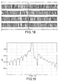
- the layout is of the type illustrated in FIG. 18.
- the lengths of the transducers are 264 periods (ie a length of approximately 4.75 mm).
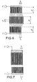
- FIG. 7 The structure of FIG. 7 has been chosen for the resonators.
- Figure 18 illustrates the representative layout of the bridge electric realized with in two arms the first resonator and in two other arms the second resonator.
- the two E + inputs are connected in parallel by a wire and not a track.
- the filter is designed to operate with an impedance of 4,000 ⁇ with an inductor in parallel. Its transfer function is illustrated in figure 19.
Landscapes
- Physics & Mathematics (AREA)
- Acoustics & Sound (AREA)
- Surface Acoustic Wave Elements And Circuit Networks Thereof (AREA)
Description
- les résonateurs sont couplés électriquement pour former un pont électrique à 4 bras ;
- 2 bras comportant deux sous-ensembles identiques E1 et E3 de N1 résonateurs chacun montés en parallèle ;
- 2 bras comportant deux sous-ensembles identiques E2 et E4 de N2 résonateurs chacun montés en parallèle ;
- avec N1 + N2 = N ;
- le produit de la capacité statique totale du sous-ensemble E1 par la capacité statique totale du sous-ensemble E3 étant sensiblement équivalent au produit de la capacité statique totale du sous-ensemble E2 par la capacité statique totale du sous-ensemble E4, de manière à équilibrer le pont électrique.
- la figure 1 schématise un résonateur avec un transducteur inséré entre des réseaux réflecteurs ;
- la figure 2 illustre une configuration de filtre selon l'art connu, monté dans une structure de pont ;
- la figure 3 schématise une configuration générale de filtre à ondes acoustiques de surface selon l'invention ;
- la figure 4 illustre une implantation de filtre à ondes acoustiques de surface de l'art antérieur, à deux pôles ;
- la figure 5a schématise une implantation de filtre à ondes acoustiques de surface comprenant deux résonateurs montés en parallèle ;
- la figure 5b illustre un premier exemple d'implantation de résonateur équivalent à deux résonateurs montés en parallèle représentés en figure 5a ;
- la figure 6 illustre un deuxième exemple d'implantation de résonateur équivalent à deux résonateurs montés en parallèle, utilisant trois voies acoustiques ;
- la figure 7 illustre un troisième exemple d'implantation de résonateur équivalent à deux résonateurs montés en parallèle, utilisant deux voies acoustiques, mais décalés d'un pas pi ;
- la figure 8 illustre un quatrième exemple d'implantation de résonateur équivalent à deux résonateurs montés en parallèle, utilisant l'excitation de modes symétriques et de modes antisymétriques longitudinalement ;
- la figure 9 illustre l'admittance d'un exemple de transducteur de type DART, dans lequel le centre d'une cellule de transduction est séparé du centre d'une cellule de réflexion adjacente, d'une distance 3λ/8 ;
- la figure 10 illustre l'évolution de la conductance du même transducteur de type DART, dans lequel le centre d'une cellule de transduction est séparé du centre d'une cellule de réflexion adjacente, d'une distance variant de (3 - 0,4) λ /8 à (3 + 0,4) λ/8 ;
- la figure 11 illustre l'évolution de la susceptance du même transducteur de type DART, dans lequel le centre d'une cellule de transduction est séparé du centre d'une cellule de réflexion adjacente, d'une distance variant de (3 - 0,4) λ/8 à (3+0,4) λ/8 ;
- la figure 12 illustre la fonction de transfert pour un exemple de filtre selon l'invention, à 4 pôles, utilisant des DART ;
- la figure 13 illustre l'admittance d'un bras de pont électrique, comprenant un DART à deux modes utilisés dans un exemple de filtre selon l'invention, à 3 pôles ;
- la figure 14 illustre l'admittance du deuxième bras de pont électrique, comprenant un DART non pondéré, dans un exemple de filtre selon l'invention à 3 pôles ;
- la figure 15 illustre la fonction de transfert du même exemple de filtre selon l'invention, à 3 pôles, comprenant un résonateur à un mode dans un bras et un résonateur à deux modes dans l'autre bras ;
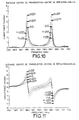
- la figure 16 illustre les conductances de deux résonateurs utilisés dans un exemple de filtre à 87 MHz selon l'invention utilisant des résonateurs du type illustré en figure 6 ;
- la figure 17 illustre les susceptances de deux résonateurs utilisés dans un exemple de filtre à 87 MHz selon l'invention utilisant des résonateurs du type illustré en figure 6 ;
- la figure 18 illustre l'implantation du filtre dont les caractéristiques sont données en figures 15, 16 et 17 ;
- la figure 19 illustre la fonction de transfert du filtre à 87 MHz réalisé selon l'invention.


Claims (15)
- Filtre à ondes acoustiques de surface à N pôles, N étant un nombre supérieur ou égal à 3, et comportant un ensemble de résonateurs, caractérisé en ce que :les résonateurs sont couplés électriquement pour former un pont électrique à 4 bras ;2 bras comportant un premier et un troisième sous-ensembles identiques (E1 et E3) de N1 résonateurs montés en parallèle ;2 bras comportant un deuxième et un quatrième sous-ensembles identiques (E2 et E4) de N2 résonateurs montés en parallèle ;avec N1 + N2 =N ;le produit de la capacité statique du premier sous-ensemble (E1) par la capacité statique du troisième sous-ensemble (E3) étant sensiblement équivalent au produit de la capacité statique du deuxième sous-ensemble (E2) par la capacité statique du quatrième sous-ensemble (E4), de manière à équilibrer le pont électrique.
- Filtre à ondes acoustiques de surface selon la revendication 1, caractérisé en ce que N est pair et N1 = N2 = N / 2.
- Filtre à ondes acoustiques de surface selon la revendication 1, caractérisé en ce que N est impair et N1 = (N -1) / 2 et N2 = (N + 1) / 2.
- Filtre à ondes acoustiques de surface selon l'une des revendications 1 à 3, caractérisé en ce qu'au moins un bras comporte un unique dispositif à ondes de surface ayant une admittance équivalente à la mise en parallèle d'un sous-ensemble de résonateurs.
- Filtre à ondes acoustiques de surface selon l'une des revendications 1 à 4, caractérisé en ce qu'au moins un bras comporte une structure équivalente à plusieurs résonateurs montés en parallèle, ladite structure comportant deux réseaux d'électrodes interdigitées constitutifs de la partie transduction des résonateurs, lesdits réseaux étant connectés à deux bus de polarités différentes et comprenant m voies acoustiques insérées entre les deux bus, la ième voie acoustique possédant un pas pi d'électrodes, sur une longueur d'électrodes wi et 1 ≤ i ≤ m.
- Filtre à ondes acoustiques de surface selon la revendication 5, caractérisé en ce que la ième voie acoustique comporte de chaque côté de la partie transduction deux réseaux réflecteurs.
- Filtre à ondes acoustiques de surface selon l'une des revendications 5 ou 6, caractérisé en ce que les deux voies acoustiques consécutives sont reliées entre elles par des métallisations mi, connectant les électrodes séparées d'un pas pi aux électrodes séparées d'un pas pi+1.
- Filtre à ondes acoustiques de surface selon l'une des revendications 5 à 7, caractérisé en ce qu'au moins un bras comprend une structure équivalente à deux résonateurs montés en parallèle et ladite structure comporte une voie acoustique supérieure et une voie acoustique inférieure de pas d'électrodes p1 et de longueur d'électrodes w1, une voie acoustique centrale de pas d'électrodes p2 et de longueur d'électrodes w2, les électrodes du réseau d'électrodes connecté au premier bus de la voie acoustique supérieure, étant alignées avec les électrodes du réseau d'électrodes connectés au second bus de la voie acoustique inférieure.
- Filtres à ondes acoustiques de surface selon l'une des revendications 5 à 7, caractérisé en ce que pas les pas p1 et p2 sont égaux et en ce que la structure comprend deux voies acoustiques, les électrodes de chacun des réseaux d'électrodes étant décalées d'une distance p1 entre les deux voies acoustiques.
- Filtre à ondes acoustiques de surface selon l'une des revendications 1 à 3, caractérisé en ce qu'au moins un des bras comporte une structure équivalente à au moins deux résonateurs montés en parallèle, ladite structure comportant deux réseaux d'électrodes interdigitées, lesdits réseaux étant connectés à un premier et second bus de polarités différentes, de manière à définir un transducteur présentant un axe central (Z) parallèle aux électrodes, ledit transducteur comportant des électrodes positionnées symétriquement par rapport à l'axe central et reliées au premier bus et comportant des électrodes positionnées symétriquement par rapport à l'axe central et reliées au second bus de polarité opposée, de manière à exciter des modes longitudinaux symétriques et des modes longitudinaux antisymétriques.
- Filtre à ondes acoustiques de surface selon la revendication 10, caractérisé en ce que le transducteur est inséré entre deux réseaux réflecteurs.
- Filtre à ondes acoustiques de surface selon l'une des revendications 1 à 4. caractérisé en ce qu'au moins un des bras comprend un résonateur de type DART, avec des cellules transduction intercalées entre des cellules de réflexion.
- Filtre à ondes acoustiques de surface selon la revendication 12, caractérisé en ce que le résonateur de type DART comprend des cavités résonantes.
- Filtre à ondes acoustiques de surface selon l'une des revendications 12 ou 13, caractérisé en ce que le nombre de pôles est pair et en ce que la distance entre le centre de transduction d'une cellule de transduction et le centre de réflexion d'une cellule de réflexion adjacente à ladite cellule de transduction est de l'ordre de (3 ± d) λ/8 + kλ/2 avec λ longueur d'onde correspondant à la fréquence centrale du filtre, d inférieur à 1 et k entier.
- Filtre à ondes acoustiques de surface caractérisé en ce qu'il comprend la mise en série de plusieurs ensembles de résonateurs, dont au moins un ensemble de résonateurs répond à l'une des revendications 1 à 14.
Applications Claiming Priority (3)
| Application Number | Priority Date | Filing Date | Title |
|---|---|---|---|
| FR9801419 | 1998-02-06 | ||
| FR9801419A FR2774826B1 (fr) | 1998-02-06 | 1998-02-06 | Filtre a resonateurs a ondes acoustiques de surface |
| PCT/FR1999/000214 WO1999040678A1 (fr) | 1998-02-06 | 1999-02-02 | Filtre a resonateurs a ondes acoustiques de surface |
Publications (2)
| Publication Number | Publication Date |
|---|---|
| EP1053593A1 EP1053593A1 (fr) | 2000-11-22 |
| EP1053593B1 true EP1053593B1 (fr) | 2002-05-08 |
Family
ID=9522684
Family Applications (1)
| Application Number | Title | Priority Date | Filing Date |
|---|---|---|---|
| EP99901689A Expired - Lifetime EP1053593B1 (fr) | 1998-02-06 | 1999-02-02 | Filtre a resonateurs a ondes acoustiques de surface |
Country Status (9)
| Country | Link |
|---|---|
| US (1) | US6344705B1 (fr) |
| EP (1) | EP1053593B1 (fr) |
| JP (1) | JP2002503049A (fr) |
| KR (1) | KR20010040543A (fr) |
| CN (1) | CN1144361C (fr) |
| CA (1) | CA2319690A1 (fr) |
| DE (1) | DE69901426T2 (fr) |
| FR (1) | FR2774826B1 (fr) |
| WO (1) | WO1999040678A1 (fr) |
Families Citing this family (21)
| Publication number | Priority date | Publication date | Assignee | Title |
|---|---|---|---|---|
| DE10026074B4 (de) * | 2000-05-25 | 2010-02-18 | Epcos Ag | Rekursives OFW-Filter mit geringer Chiplänge |
| JP3863712B2 (ja) * | 2000-09-06 | 2006-12-27 | 株式会社日立製作所 | 弾性表面波共振器 |
| JP3445261B2 (ja) | 2000-09-13 | 2003-09-08 | 松下電器産業株式会社 | 弾性表面波フィルタ及びこれを用いた通信機器 |
| JP3824498B2 (ja) * | 2000-09-28 | 2006-09-20 | 富士通株式会社 | 弾性表面波フィルタ |
| US6924715B2 (en) * | 2002-02-12 | 2005-08-02 | Nortel Networks Limited | Band reject filters |
| JP4079658B2 (ja) * | 2002-03-05 | 2008-04-23 | 株式会社リコー | 2値化ウォブル信号を生成する回路、ライトクロック生成回路、2値化ウォブル信号を生成する方法、ライトクロック生成方法及び光ディスク装置 |
| FR2837636B1 (fr) * | 2002-03-19 | 2004-09-24 | Thales Sa | Dispositif a ondes acoustiques d'interface en tantalate de lithium |
| JP3963824B2 (ja) * | 2002-11-22 | 2007-08-22 | 富士通メディアデバイス株式会社 | フィルタ素子、それを有するフィルタ装置、分波器及び高周波回路 |
| DE10319554B4 (de) * | 2003-04-30 | 2018-05-09 | Snaptrack, Inc. | Mit akustischen Volumenwellen arbeitendes Bauelement mit gekoppelten Resonatoren |
| FR2864618B1 (fr) * | 2003-12-24 | 2006-03-03 | Temex Sa | Capteur de temperature ou de temperature et de pression interrogeable a distance |
| JP4586404B2 (ja) * | 2004-04-28 | 2010-11-24 | ソニー株式会社 | フィルタ装置及び送受信機 |
| JP4800026B2 (ja) * | 2005-12-16 | 2011-10-26 | 三星電子株式会社 | 複素係数トランスバーサルフィルタおよび周波数変換器 |
| DE202006007423U1 (de) * | 2006-05-09 | 2007-09-13 | EKATO Rühr- und Mischtechnik GmbH | Rührorgan |
| JP5237138B2 (ja) * | 2009-01-27 | 2013-07-17 | 太陽誘電株式会社 | フィルタ、デュープレクサ、通信モジュール |
| JP6160120B2 (ja) * | 2013-02-28 | 2017-07-12 | セイコーエプソン株式会社 | 超音波トランスデューサーデバイス、超音波測定装置、ヘッドユニット、プローブ及び超音波画像装置 |
| JP6135184B2 (ja) * | 2013-02-28 | 2017-05-31 | セイコーエプソン株式会社 | 超音波トランスデューサーデバイス、ヘッドユニット、プローブ及び超音波画像装置 |
| US10574203B2 (en) * | 2015-07-28 | 2020-02-25 | Qorvo Us, Inc. | Bonded wafers and surface acoustic wave devices using same |
| US10084427B2 (en) | 2016-01-28 | 2018-09-25 | Qorvo Us, Inc. | Surface acoustic wave device having a piezoelectric layer on a quartz substrate and methods of manufacturing thereof |
| US10128814B2 (en) | 2016-01-28 | 2018-11-13 | Qorvo Us, Inc. | Guided surface acoustic wave device providing spurious mode rejection |
| US11206007B2 (en) | 2017-10-23 | 2021-12-21 | Qorvo Us, Inc. | Quartz orientation for guided SAW devices |
| US12438520B2 (en) * | 2021-09-01 | 2025-10-07 | Rf360 Singapore Pte. Ltd. | Electroacoustic filter with low phase delay for multiplexed signals |
Family Cites Families (19)
| Publication number | Priority date | Publication date | Assignee | Title |
|---|---|---|---|---|
| US3435259A (en) * | 1965-05-13 | 1969-03-25 | Us Army | Filter circuit |
| FR2250102B1 (fr) | 1973-10-31 | 1976-10-01 | Thomson Csf | |
| FR2266394B1 (fr) | 1974-03-26 | 1981-02-27 | Thomson Csf | |
| FR2326094A1 (fr) | 1975-09-26 | 1977-04-22 | Thomson Csf | Dispositif de lecture bidimensionnelle d'image optique, utilisant des ondes elastiques de surface |
| FR2365138A1 (fr) | 1976-09-17 | 1978-04-14 | Thomson Csf | Systeme de codage par modulation d'un signal lumineux |
| JPS6352509A (ja) * | 1986-08-22 | 1988-03-05 | Clarion Co Ltd | コンボルバ最適バイアス回路 |
| GB2197559B (en) * | 1986-08-22 | 1990-03-28 | Clarion Co Ltd | Bias voltage circuit for a convolver |
| FR2628265B1 (fr) | 1987-03-06 | 1990-12-21 | Thomson Csf | Antenne directive a transducteurs multiples notamment pour sonar |
| FR2612711A1 (fr) | 1987-03-19 | 1988-09-23 | Thomson Csf | Procede de correction d'un dispositif a ondes de surface, notamment pour un filtre dispersif |
| US5264751A (en) | 1989-10-20 | 1993-11-23 | Thomson-Csf | Unilateral surface wave transducer |
| US5028895A (en) * | 1990-05-29 | 1991-07-02 | Motorola, Inc. | Notch filter for reducing clock signal feedthrough effects in an acoustic charge transport device |
| FR2682833B1 (fr) | 1991-10-18 | 1993-12-03 | Thomson Csf | Filtre a ondes de surface et a trajet acoustique replie. |
| US5703427A (en) | 1993-03-19 | 1997-12-30 | Thomson-Csf | Surface-wave distributed acoustic reflection transducer and filter including such a transducer |
| GB2280806B (en) * | 1993-08-04 | 1997-10-08 | Advanced Saw Prod Sa | Saw filter |
| US5847626A (en) * | 1994-02-22 | 1998-12-08 | Matsushita Electric Industrial Co., Ltd. | Balanced-type surface acoustic wave lattice filter |
| FR2739232B1 (fr) | 1995-09-26 | 1997-10-24 | Thomson Csf | Filtre a ondes acoustiques de surface utilisant le couplage de trois voies acoustiques |
| FR2740908B1 (fr) | 1995-11-07 | 1997-11-28 | Thomson Csf | Transducteur a ondes acoustiques de surface attaque en differentiel |
| GB2312109B (en) * | 1996-03-29 | 2000-08-02 | Advanced Saw Prod Sa | Acoustic wave filter |
| FR2762458B1 (fr) | 1997-04-18 | 1999-07-09 | Thomson Csf | Dispositif a ondes acoustiques de surface a couplage par proximite a entrees/sorties differentielles |
-
1998
- 1998-02-06 FR FR9801419A patent/FR2774826B1/fr not_active Expired - Fee Related
-
1999
- 1999-02-02 KR KR1020007008408A patent/KR20010040543A/ko not_active Ceased
- 1999-02-02 WO PCT/FR1999/000214 patent/WO1999040678A1/fr not_active Ceased
- 1999-02-02 JP JP2000530978A patent/JP2002503049A/ja active Pending
- 1999-02-02 CN CNB998025666A patent/CN1144361C/zh not_active Expired - Fee Related
- 1999-02-02 EP EP99901689A patent/EP1053593B1/fr not_active Expired - Lifetime
- 1999-02-02 CA CA002319690A patent/CA2319690A1/fr not_active Abandoned
- 1999-02-02 US US09/601,321 patent/US6344705B1/en not_active Expired - Fee Related
- 1999-02-02 DE DE69901426T patent/DE69901426T2/de not_active Expired - Lifetime
Also Published As
| Publication number | Publication date |
|---|---|
| FR2774826A1 (fr) | 1999-08-13 |
| FR2774826B1 (fr) | 2000-05-05 |
| DE69901426T2 (de) | 2003-01-16 |
| DE69901426D1 (de) | 2002-06-13 |
| US6344705B1 (en) | 2002-02-05 |
| HK1035969A1 (en) | 2001-12-14 |
| CA2319690A1 (fr) | 1999-08-12 |
| EP1053593A1 (fr) | 2000-11-22 |
| KR20010040543A (ko) | 2001-05-15 |
| JP2002503049A (ja) | 2002-01-29 |
| CN1144361C (zh) | 2004-03-31 |
| CN1289478A (zh) | 2001-03-28 |
| WO1999040678A1 (fr) | 1999-08-12 |
Similar Documents
| Publication | Publication Date | Title |
|---|---|---|
| EP1053593B1 (fr) | Filtre a resonateurs a ondes acoustiques de surface | |
| CA2121477C (fr) | Filtre a ondes de surface et a trajet acoustique replie | |
| EP3996275B1 (fr) | Dispositif électromécanique à fréquence de résonance ajustable | |
| EP0872954B1 (fr) | Dispositif à ondes acoustiques de surface à couplage par proximité à entrées/sorties différentielles | |
| FR2834593A1 (fr) | Resonateur piezoelectrique et filtre piezoelectrique, duplexeur et appareil de communication l'incluant | |
| FR2821997A1 (fr) | Filtre a ondes acoustiques de surface | |
| FR2739232A1 (fr) | Filtre a ondes acoustiques de surface utilisant le couplage de trois voies acoustiques | |
| EP4409743A1 (fr) | Filtre à ondes élastiques de surface et à cavités résonantes | |
| EP0660981A1 (fr) | Transducteur d'ondes unidirectionnel. | |
| EP2901551B1 (fr) | Dispositif acoustique comprenant un cristal phononique reglable a base d'elements piezoelectriques | |
| EP2509221B1 (fr) | Dispositif utilisant un filtre à base de résonateurs | |
| EP0982859B1 (fr) | Filtre acoustique à deux canaux différents à compensation de réjection | |
| WO1993013595A1 (fr) | Filtre a ondes de surface | |
| FR2818051A1 (fr) | Flitres a ondes acoustiques de surface a symetrie optimisee | |
| WO2004055981A2 (fr) | Filtre dms a faibles pertes d'insertion et symetrie optimisee | |
| FR3162108A1 (fr) | Dispositif à ondes élastiques | |
| EP0646296B2 (fr) | Transducteur a ondes de surface a reflexion acoustique distribuee et filtre comportant un tel transducteur | |
| EP0576340B1 (fr) | Filtre à ondes de surface à réseaux réfléchissants | |
| WO2004006432A2 (fr) | Filtre a ondes acoustiques de surface a double mode symetrique optimise | |
| FR2621431A1 (fr) | Filtre a ondes de surface utilisant des transducteurs en forme de peignes comportant des doigts ponderes par variation de la longueur de recouvrement de ces doigts |
Legal Events
| Date | Code | Title | Description |
|---|---|---|---|
| PUAI | Public reference made under article 153(3) epc to a published international application that has entered the european phase |
Free format text: ORIGINAL CODE: 0009012 |
|
| 17P | Request for examination filed |
Effective date: 20000329 |
|
| AK | Designated contracting states |
Kind code of ref document: A1 Designated state(s): DE FI FR GB IT SE |
|
| GRAG | Despatch of communication of intention to grant |
Free format text: ORIGINAL CODE: EPIDOS AGRA |
|
| 17Q | First examination report despatched |
Effective date: 20010312 |
|
| GRAG | Despatch of communication of intention to grant |
Free format text: ORIGINAL CODE: EPIDOS AGRA |
|
| GRAH | Despatch of communication of intention to grant a patent |
Free format text: ORIGINAL CODE: EPIDOS IGRA |
|
| GRAH | Despatch of communication of intention to grant a patent |
Free format text: ORIGINAL CODE: EPIDOS IGRA |
|
| RAP1 | Party data changed (applicant data changed or rights of an application transferred) |
Owner name: THALES |
|
| REG | Reference to a national code |
Ref country code: GB Ref legal event code: IF02 |
|
| GRAA | (expected) grant |
Free format text: ORIGINAL CODE: 0009210 |
|
| AK | Designated contracting states |
Kind code of ref document: B1 Designated state(s): DE FI FR GB IT SE |
|
| REF | Corresponds to: |
Ref document number: 69901426 Country of ref document: DE Date of ref document: 20020613 |
|
| GBT | Gb: translation of ep patent filed (gb section 77(6)(a)/1977) |
Effective date: 20020720 |
|
| PLBE | No opposition filed within time limit |
Free format text: ORIGINAL CODE: 0009261 |
|
| STAA | Information on the status of an ep patent application or granted ep patent |
Free format text: STATUS: NO OPPOSITION FILED WITHIN TIME LIMIT |
|
| 26N | No opposition filed |
Effective date: 20030211 |
|
| PGFP | Annual fee paid to national office [announced via postgrant information from national office to epo] |
Ref country code: GB Payment date: 20050202 Year of fee payment: 7 |
|
| PGFP | Annual fee paid to national office [announced via postgrant information from national office to epo] |
Ref country code: SE Payment date: 20050204 Year of fee payment: 7 |
|
| PGFP | Annual fee paid to national office [announced via postgrant information from national office to epo] |
Ref country code: FI Payment date: 20050214 Year of fee payment: 7 |
|
| PG25 | Lapsed in a contracting state [announced via postgrant information from national office to epo] |
Ref country code: GB Free format text: LAPSE BECAUSE OF NON-PAYMENT OF DUE FEES Effective date: 20060202 Ref country code: FI Free format text: LAPSE BECAUSE OF NON-PAYMENT OF DUE FEES Effective date: 20060202 |
|
| PG25 | Lapsed in a contracting state [announced via postgrant information from national office to epo] |
Ref country code: SE Free format text: LAPSE BECAUSE OF NON-PAYMENT OF DUE FEES Effective date: 20060203 |
|
| PGFP | Annual fee paid to national office [announced via postgrant information from national office to epo] |
Ref country code: IT Payment date: 20060228 Year of fee payment: 8 |
|
| EUG | Se: european patent has lapsed | ||
| GBPC | Gb: european patent ceased through non-payment of renewal fee |
Effective date: 20060202 |
|
| PG25 | Lapsed in a contracting state [announced via postgrant information from national office to epo] |
Ref country code: IT Free format text: LAPSE BECAUSE OF NON-PAYMENT OF DUE FEES Effective date: 20070202 |
|
| PGFP | Annual fee paid to national office [announced via postgrant information from national office to epo] |
Ref country code: FR Payment date: 20090217 Year of fee payment: 11 |
|
| REG | Reference to a national code |
Ref country code: FR Ref legal event code: ST Effective date: 20101029 |
|
| PG25 | Lapsed in a contracting state [announced via postgrant information from national office to epo] |
Ref country code: FR Free format text: LAPSE BECAUSE OF NON-PAYMENT OF DUE FEES Effective date: 20100301 |
|
| REG | Reference to a national code |
Ref country code: DE Ref legal event code: R082 Ref document number: 69901426 Country of ref document: DE Representative=s name: BARDEHLE PAGENBERG PARTNERSCHAFT MBB PATENTANW, DE Ref country code: DE Ref legal event code: R081 Ref document number: 69901426 Country of ref document: DE Owner name: SNAPTRACK, INC., SAN DIEGO, US Free format text: FORMER OWNER: EPCOS AG, 81669 MUENCHEN, DE |
|
| PGFP | Annual fee paid to national office [announced via postgrant information from national office to epo] |
Ref country code: DE Payment date: 20180207 Year of fee payment: 20 |
|
| REG | Reference to a national code |
Ref country code: DE Ref legal event code: R071 Ref document number: 69901426 Country of ref document: DE |