EP1053670A1 - Böschungsmäher - Google Patents
Böschungsmäher Download PDFInfo
- Publication number
- EP1053670A1 EP1053670A1 EP00440121A EP00440121A EP1053670A1 EP 1053670 A1 EP1053670 A1 EP 1053670A1 EP 00440121 A EP00440121 A EP 00440121A EP 00440121 A EP00440121 A EP 00440121A EP 1053670 A1 EP1053670 A1 EP 1053670A1
- Authority
- EP
- European Patent Office
- Prior art keywords
- cylinder
- orifice
- rod
- hydraulic cylinder
- hydraulic
- Prior art date
- Legal status (The legal status is an assumption and is not a legal conclusion. Google has not performed a legal analysis and makes no representation as to the accuracy of the status listed.)
- Granted
Links
- 230000000694 effects Effects 0.000 description 6
- 230000005484 gravity Effects 0.000 description 3
- 244000025254 Cannabis sativa Species 0.000 description 2
- 238000013459 approach Methods 0.000 description 2
- 230000001681 protective effect Effects 0.000 description 2
- 230000007547 defect Effects 0.000 description 1
- 230000001687 destabilization Effects 0.000 description 1
- 238000006073 displacement reaction Methods 0.000 description 1
- 230000007257 malfunction Effects 0.000 description 1
- 238000012544 monitoring process Methods 0.000 description 1
- 239000011435 rock Substances 0.000 description 1
- 238000006467 substitution reaction Methods 0.000 description 1
- 238000009966 trimming Methods 0.000 description 1
Images


Classifications
-
- A—HUMAN NECESSITIES
- A01—AGRICULTURE; FORESTRY; ANIMAL HUSBANDRY; HUNTING; TRAPPING; FISHING
- A01D—HARVESTING; MOWING
- A01D34/00—Mowers; Mowing apparatus of harvesters
- A01D34/835—Mowers; Mowing apparatus of harvesters specially adapted for particular purposes
- A01D34/86—Mowers; Mowing apparatus of harvesters specially adapted for particular purposes for use on sloping ground, e.g. on embankments or in ditches
- A01D34/866—Mounting means
Definitions
- the present invention relates to a mowing machine comprising a frame capable of being hooked to a tractor and carrying a tool arm which is made of at least one inner part which is articulated by means of an axis substantially horizontal on a support of the frame and at least one external part which is articulated on said inner part by means of an axis substantially horizontal and carrying a cutting tool.
- the inner part of the arm can be moved around its axis of articulation by means of a first hydraulic cylinder which is located between said inner part and the support of the frame and which has a cylinder in which a rod moves with a piston.
- Mowing machines of this type are mainly intended for cutting grass and brush, for example on meadows, borders of roads, ditches and embankments or cutting hedges or tree branches.
- the first hydraulic cylinder is single acting type.
- This cylinder allows to move the tool arm around the axis of articulation of the inner part of the arm, in order to adjust the position of the tool cutting.
- the movement of said arm upwards is carried out by means of the jack hydraulic. Its downward movement is effected by its own weight.
- Such an arrangement allows in particular the cutting tool to match the uneven ground without operator intervention.
- the weight of the tool, with the large offset when the arm is extended, causes the assembly to exert a force sufficient to keep the tool in the position chosen by the operator.
- the object of the present invention is to remedy the aforementioned drawbacks of known machines, using simple means and operating in a way relatively safe.
- an important characteristic of the invention consists in that the cylinder of the first hydraulic cylinder has near one of its ends a first oil inlet and outlet port which is connected by means of a hose to a hydraulic distributor and near its other end a second orifice which is also connected to the hydraulic distributor by means of a hose and a third port which is connected to a reservoir and which is closed automatically by the piston or rod of this first hydraulic cylinder when said rod is close from the position where it has extended to the maximum from the cylinder.
- the hydraulic cylinder works in simple mode effect on most of its course, in order to facilitate the monitoring of uneven ground.
- the oil which is located on the side of the cylinder which contains the third port freely leaves towards the tank and has no effect on the piston.
- this hydraulic cylinder automatically switches to double-acting mode, by following the obturation of the third orifice, when the center of gravity of the arm and the tool approaches the vertical plane passing through the axis of articulation of said arm on the frame support.
- This hydraulic cylinder then prevents the arm from tipping around of said axis of articulation. The operator thus keeps control of the arm position of the cutting tool.
- the machine according to the invention comprises a frame (1) which can be hooked to the lifting device of a tractor (2).
- the frame (1) has a substantially vertical axis (3) on which is articulated a support (4).
- a substantially horizontal hydraulic cylinder (5) is connected to said support (4) and allows to move it around the axis (3).
- On this support (4) is articulated a tool-carrying arm (6) which is made in at least two parts (7 and 8) in form of beams and which are foldable relative to each other.
- the part inner (7) is articulated with its lower end on the support (4) at by means of a substantially horizontal axis (9).
- This inner part (7) is movable around said axis (9) by means of a first hydraulic cylinder (10).
- the outer part (8) of the tool holder arm (6) is articulated on the inner part (7) using a substantially horizontal axis (13).
- This outer part (8) can be moved around the axis (13) by means of a second hydraulic cylinder (14).
- the latter is articulated on legs (15) of the inner part (7) and lugs (16) provided on said outer part (8).
- a cutting tool (17) is articulated by means of an axis (18) on the free end of the second part (8) of the arm (6).
- This cutting tool (17) notably consists a rotor which is equipped with knives or flails on its periphery and which can be rotated by a hydraulic motor.
- This rotor is partially surrounded by a protective cover (19) which is provided with lateral pads (20 and 21) which can slide on the ground.
- This cutting tool (17) is movable around its axis articulation (18) using a third hydraulic cylinder (22) which is articulated on lugs (23) of said tool (17) and on lugs (24) of the outer part (8) of the arm (6).
- the aforementioned hydraulic cylinders (5, 10, 14 and 22) are connected to a hydraulic unit which can be on the machine or on the tractor (2). Their movements are controlled by the operator by means of distributors hydraulics that it can operate from the tractor (2).
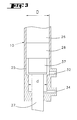
- the first cylinder hydraulic (10) has a cylinder (25) with a bore (26) in which moves a rod (27) with a piston (28).
- Said cylinder (25) comprises, close to its upper end which is articulated to the tool-carrying arm (6), a first orifice (29) oil inlet and outlet.
- This orifice (29) is connected via a hose (30) to a hydraulic distributor (31) which controls the inlet and outlet of the oil from the part of the cylinder (25) which is located between its upper end and the piston (28).
- This cylinder (25) has near its lower end a second orifice (32).
- This is also connected via a hose (33) to the hydraulic distributor (31) which thus controls the arrival and the exit of the oil from the part of the cylinder (25) which is located between its lower end and the piston (28).
- This cylinder (25) has a third near the second orifice (32) orifice (34) which is connected to a reservoir (35) by means of a pipe (36).
- This third orifice (34) can be closed automatically by the piston (28) or the rod (27) of the first hydraulic cylinder (10) when said rod (27) is close to the position where it has extended as far as possible from the cylinder (25).
- the rod (27) has a shoulder (37).
- the internal bore (26) of the cylinder (25) present in the part where the third orifice (34) a diameter (d) which is slightly less than the diameter (D) of the part of said bore (26) which has the first and second orifices (29 and 32).
- the reduced diameter (d) corresponds to the diameter of the shoulder (37).
- the piston (28) and the rod (27) are made so that said piston (28) is located between the first port (29) and the second port (32).
- the oil arriving by the first orifice (29) causes a displacement of the piston (28) and the rod (27) so that the cylinder (10) lengthens.
- the oil arriving in the cylinder (25) through the second port (32) exits through the third port (34) when this one is open. It then has no effect on the piston (28) and the rod (27).
- the first hydraulic cylinder (10) works in single-acting mode.
- the access to the third orifice (34) is closed by the shoulder (37)
- the oil arriving in the cylinder (10) through the second orifice (32) moves the piston (28) and the rod (27) so that the cylinder (10) shortens. This one then works in double effect mode.
- the cutting tool (17) can be moved away from or closer to the tractor (2) and be moved in height by means of the parts (7 and 8) which make up the arm (6).
- These parts (7 and 8) are themselves movable around their axes articulation (9 and 13) using the first and second hydraulic cylinders (10 and 14).
- the third hydraulic cylinder (22) allows to orient the cutting tool (17) around its axis of articulation (18).
- the rotor of the cutting tool (17) is then rotated by the motor hydraulic.
- the tool (17) slides on the surface of the ground by means of the pads (20 and 21). he can advantageously follow the differences in level thanks to the fact that in this position the first hydraulic cylinder (10) is in single acting mode, which allows the part inside (7) of the arm (6) to pivot freely up and down.
- the cutting tool (17) can also be lifted by means of the arm (6) for the trimming of hedges or tree branches (see Figure 1).
- the first hydraulic cylinder (10) is controlled by means of the distributor (31) so that it lengthens while the second hydraulic cylinder (14) is controlled so that it shortens.
- the first hydraulic cylinder (10) is in single effect mode for most of its travel.
- the cutting tool (17) then remains in the chosen position under the effect of its own weight.
- the shoulder (37) of the rod (27) is introduced into the portion of the bore (26) of the cylinder (25), the diameter is reduced and closes the oil access to the third orifice (34).
- the operator can then control, from the distributor (31), the movements of the rod (27) of the first hydraulic cylinder (10) in both directions. He keeps the control of the position of the arm (6) and of the cutting tool (17) even when their center of gravity passes beyond a vertical plane (P) passing through the axis articulation (9) of the arm (6) on the support (4) of the frame (1). In this way, he can prevent the arm (6) from tilting suddenly into its extreme position. He can too gently bring it back down from its extreme position.
- the inner part (7) of the arm (6) can be directed towards the top using the first hydraulic cylinder (10) and the second part (8) can be folded down, around its axis (13), by means of the second cylinder hydraulic (14). The overall size of the assembly is then reduced.
Landscapes
- Life Sciences & Earth Sciences (AREA)
- Environmental Sciences (AREA)
- Harvester Elements (AREA)
- Lifting Devices For Agricultural Implements (AREA)
Applications Claiming Priority (2)
| Application Number | Priority Date | Filing Date | Title |
|---|---|---|---|
| FR9906549A FR2793647B1 (fr) | 1999-05-20 | 1999-05-20 | Machine de fauchage avec un bras porte-outil deplacable hydrauliquement |
| FR9906549 | 1999-05-20 |
Publications (2)
| Publication Number | Publication Date |
|---|---|
| EP1053670A1 true EP1053670A1 (de) | 2000-11-22 |
| EP1053670B1 EP1053670B1 (de) | 2004-01-14 |
Family
ID=9545932
Family Applications (1)
| Application Number | Title | Priority Date | Filing Date |
|---|---|---|---|
| EP00440121A Expired - Lifetime EP1053670B1 (de) | 1999-05-20 | 2000-05-03 | Böschungsmäher |
Country Status (4)
| Country | Link |
|---|---|
| EP (1) | EP1053670B1 (de) |
| AT (1) | ATE257642T1 (de) |
| DE (1) | DE60007685T2 (de) |
| FR (1) | FR2793647B1 (de) |
Cited By (3)
| Publication number | Priority date | Publication date | Assignee | Title |
|---|---|---|---|---|
| FR2869195A1 (fr) * | 2004-04-22 | 2005-10-28 | Signalisation Moderne Autorout | Machine pour effectuer des travaux de fauchage/ debroussaillage et d'elagage |
| GB2435802A (en) * | 2006-03-07 | 2007-09-12 | Kuhn Audureau Sa | A hedge and grass cutter |
| EP2733364A1 (de) * | 2012-11-16 | 2014-05-21 | Kuhn S.A. | Doppelt wirkende Zylinder mit einer zusätzlichen Öffnung und Landwirtschaftliche Maschine mit einem solchen Zylinder |
Citations (4)
| Publication number | Priority date | Publication date | Assignee | Title |
|---|---|---|---|---|
| DE3218525A1 (de) * | 1982-05-17 | 1983-11-17 | Gerhard Dücker KG Landmaschinenfabrik, 4424 Stadtlohn | Boeschungsmaehgeraet |
| FR2612363A1 (fr) * | 1987-03-21 | 1988-09-23 | Mcconnel F W Ltd | Dispositif de coupe de vegetation |
| DE19611281A1 (de) * | 1996-03-22 | 1997-09-25 | Fiedler Maschinenbau Und Techn | Auflagedruckregelung für ein am Erdboden arbeitendes landwirtschaftliches Arbeitswerkzeug |
| FR2779903A1 (fr) * | 1998-06-17 | 1999-12-24 | Noremat | Dispositif securise pour la coupe des vegetaux |
-
1999
- 1999-05-20 FR FR9906549A patent/FR2793647B1/fr not_active Expired - Fee Related
-
2000
- 2000-05-03 DE DE2000607685 patent/DE60007685T2/de not_active Expired - Lifetime
- 2000-05-03 EP EP00440121A patent/EP1053670B1/de not_active Expired - Lifetime
- 2000-05-03 AT AT00440121T patent/ATE257642T1/de not_active IP Right Cessation
Patent Citations (4)
| Publication number | Priority date | Publication date | Assignee | Title |
|---|---|---|---|---|
| DE3218525A1 (de) * | 1982-05-17 | 1983-11-17 | Gerhard Dücker KG Landmaschinenfabrik, 4424 Stadtlohn | Boeschungsmaehgeraet |
| FR2612363A1 (fr) * | 1987-03-21 | 1988-09-23 | Mcconnel F W Ltd | Dispositif de coupe de vegetation |
| DE19611281A1 (de) * | 1996-03-22 | 1997-09-25 | Fiedler Maschinenbau Und Techn | Auflagedruckregelung für ein am Erdboden arbeitendes landwirtschaftliches Arbeitswerkzeug |
| FR2779903A1 (fr) * | 1998-06-17 | 1999-12-24 | Noremat | Dispositif securise pour la coupe des vegetaux |
Cited By (5)
| Publication number | Priority date | Publication date | Assignee | Title |
|---|---|---|---|---|
| FR2869195A1 (fr) * | 2004-04-22 | 2005-10-28 | Signalisation Moderne Autorout | Machine pour effectuer des travaux de fauchage/ debroussaillage et d'elagage |
| GB2435802A (en) * | 2006-03-07 | 2007-09-12 | Kuhn Audureau Sa | A hedge and grass cutter |
| GB2435802B (en) * | 2006-03-07 | 2010-11-24 | Kuhn Audureau Sa | A hedge and grass cutter |
| EP2733364A1 (de) * | 2012-11-16 | 2014-05-21 | Kuhn S.A. | Doppelt wirkende Zylinder mit einer zusätzlichen Öffnung und Landwirtschaftliche Maschine mit einem solchen Zylinder |
| FR2998341A1 (fr) * | 2012-11-16 | 2014-05-23 | Kuhn Sa | Verin a double effet avec un orifice additionnel et machine agricole presentant un tel verin |
Also Published As
| Publication number | Publication date |
|---|---|
| FR2793647B1 (fr) | 2001-07-27 |
| FR2793647A1 (fr) | 2000-11-24 |
| EP1053670B1 (de) | 2004-01-14 |
| DE60007685T2 (de) | 2005-01-13 |
| ATE257642T1 (de) | 2004-01-15 |
| DE60007685D1 (de) | 2004-02-19 |
Similar Documents
| Publication | Publication Date | Title |
|---|---|---|
| EP0570315B1 (de) | Landwirtschaftliche Maschine, insbesondere Mähmaschine, mit einer verbesserten Vorrichtung zum Entlasten und zum Anheben | |
| EP0452237B1 (de) | Landwirtschaftliche Maschine mit einer Vorrichtung zur Ermittlung der Zwischenstellung des Verbindungsmittels | |
| EP2225933B1 (de) | Bewegliche Schneidevorrichtung | |
| EP2871924B1 (de) | Schneidemaschine | |
| FR2992143A1 (fr) | Dispositif d'accouplement perfectionne et machine agricole comportant un tel dispositif | |
| EP0552120B1 (de) | Heumaschine mit dynamischer Entlastungsvorrichtung | |
| FR2675980A1 (fr) | Machine de coupe perfectionnee avec structure d'attelage pivotante. | |
| FR2993904A1 (fr) | Chargeur frontal | |
| FR2946497A1 (fr) | Elagueuse autonome | |
| FR2816166A1 (fr) | Machine robotisee de taille d'arbustes ou d'arbres tels que des arbres fruitiers | |
| CA2629914A1 (fr) | Engin agricole comportant un attelage perfectionne | |
| EP1843653B1 (de) | Mähmaschine mit verbesserter aus- und einfaltvorrichtung | |
| EP1053670B1 (de) | Böschungsmäher | |
| FR2779903A1 (fr) | Dispositif securise pour la coupe des vegetaux | |
| FR2966322A1 (fr) | Machine de recolte avec un dispositif d'allegement | |
| FR2869195A1 (fr) | Machine pour effectuer des travaux de fauchage/ debroussaillage et d'elagage | |
| FR2856884A1 (fr) | Machine pour la coupe de vegetaux | |
| EP0579564B1 (de) | Mit einem Schlepper zu verbindender Mäher mit einer verbesserten Abstellvorrichtung | |
| FR2687891A1 (fr) | Faucheuse avec un organe de protection perfectionne. | |
| FR2539157A1 (fr) | Trancheuse a fleche | |
| FR2569216A1 (fr) | Dispositif pour le curage, en particulier de saignees perpendiculaires a une voie routiere | |
| EP1319761A1 (de) | Gerät zum Graben und/oder Reinigen von Gräben und Fahrzeug ausgerüstet mit solch einem Gerät | |
| FR2752664A1 (fr) | Traceur de voies pour un distributeur a usage agricole | |
| FR2866781A1 (fr) | Dispositif de suspension d'un outil de coupe ou de broyage a un elemnt porteur comportant des moyens permettant de commander son mouvement d'abaissement et/ou de soulevement | |
| FR2748629A1 (fr) | Appareillage pliable de traitemement de sol ou de vegetaux |
Legal Events
| Date | Code | Title | Description |
|---|---|---|---|
| PUAI | Public reference made under article 153(3) epc to a published international application that has entered the european phase |
Free format text: ORIGINAL CODE: 0009012 |
|
| AK | Designated contracting states |
Kind code of ref document: A1 Designated state(s): AT BE CH CY DE DK ES FI FR GB GR IE IT LI LU MC NL PT SE |
|
| AX | Request for extension of the european patent |
Free format text: AL;LT;LV;MK;RO;SI |
|
| 17P | Request for examination filed |
Effective date: 20010426 |
|
| AKX | Designation fees paid |
Free format text: AT BE CH CY DE DK ES FI FR GB GR IE IT LI LU MC NL PT SE |
|
| GRAP | Despatch of communication of intention to grant a patent |
Free format text: ORIGINAL CODE: EPIDOSNIGR1 |
|
| GRAS | Grant fee paid |
Free format text: ORIGINAL CODE: EPIDOSNIGR3 |
|
| GRAA | (expected) grant |
Free format text: ORIGINAL CODE: 0009210 |
|
| RIN1 | Information on inventor provided before grant (corrected) |
Inventor name: ROSTOUCHER, GUY Inventor name: PETERSCHMITT, MICKAEL Inventor name: GAILLARD, LOUIS-MARCBAETIMENT 3, APPARTEMENT 99 |
|
| AK | Designated contracting states |
Kind code of ref document: B1 Designated state(s): AT BE CH CY DE DK ES FI FR GB GR IE IT LI LU MC NL PT SE |
|
| PG25 | Lapsed in a contracting state [announced via postgrant information from national office to epo] |
Ref country code: NL Free format text: LAPSE BECAUSE OF FAILURE TO SUBMIT A TRANSLATION OF THE DESCRIPTION OR TO PAY THE FEE WITHIN THE PRESCRIBED TIME-LIMIT Effective date: 20040114 Ref country code: CY Free format text: LAPSE BECAUSE OF FAILURE TO SUBMIT A TRANSLATION OF THE DESCRIPTION OR TO PAY THE FEE WITHIN THE PRESCRIBED TIME-LIMIT Effective date: 20040114 Ref country code: AT Free format text: LAPSE BECAUSE OF FAILURE TO SUBMIT A TRANSLATION OF THE DESCRIPTION OR TO PAY THE FEE WITHIN THE PRESCRIBED TIME-LIMIT Effective date: 20040114 Ref country code: FI Free format text: LAPSE BECAUSE OF FAILURE TO SUBMIT A TRANSLATION OF THE DESCRIPTION OR TO PAY THE FEE WITHIN THE PRESCRIBED TIME-LIMIT Effective date: 20040114 Ref country code: IE Free format text: LAPSE BECAUSE OF FAILURE TO SUBMIT A TRANSLATION OF THE DESCRIPTION OR TO PAY THE FEE WITHIN THE PRESCRIBED TIME-LIMIT Effective date: 20040114 |
|
| REG | Reference to a national code |
Ref country code: GB Ref legal event code: FG4D Free format text: NOT ENGLISH |
|
| REG | Reference to a national code |
Ref country code: CH Ref legal event code: EP |
|
| REG | Reference to a national code |
Ref country code: IE Ref legal event code: FG4D Free format text: FRENCH |
|
| REF | Corresponds to: |
Ref document number: 60007685 Country of ref document: DE Date of ref document: 20040219 Kind code of ref document: P |
|
| PG25 | Lapsed in a contracting state [announced via postgrant information from national office to epo] |
Ref country code: SE Free format text: LAPSE BECAUSE OF FAILURE TO SUBMIT A TRANSLATION OF THE DESCRIPTION OR TO PAY THE FEE WITHIN THE PRESCRIBED TIME-LIMIT Effective date: 20040414 Ref country code: GR Free format text: LAPSE BECAUSE OF FAILURE TO SUBMIT A TRANSLATION OF THE DESCRIPTION OR TO PAY THE FEE WITHIN THE PRESCRIBED TIME-LIMIT Effective date: 20040414 Ref country code: DK Free format text: LAPSE BECAUSE OF FAILURE TO SUBMIT A TRANSLATION OF THE DESCRIPTION OR TO PAY THE FEE WITHIN THE PRESCRIBED TIME-LIMIT Effective date: 20040414 |
|
| PG25 | Lapsed in a contracting state [announced via postgrant information from national office to epo] |
Ref country code: ES Free format text: LAPSE BECAUSE OF FAILURE TO SUBMIT A TRANSLATION OF THE DESCRIPTION OR TO PAY THE FEE WITHIN THE PRESCRIBED TIME-LIMIT Effective date: 20040425 |
|
| PG25 | Lapsed in a contracting state [announced via postgrant information from national office to epo] |
Ref country code: LU Free format text: LAPSE BECAUSE OF NON-PAYMENT OF DUE FEES Effective date: 20040503 |
|
| GBT | Gb: translation of ep patent filed (gb section 77(6)(a)/1977) |
Effective date: 20040416 |
|
| PG25 | Lapsed in a contracting state [announced via postgrant information from national office to epo] |
Ref country code: LI Free format text: LAPSE BECAUSE OF NON-PAYMENT OF DUE FEES Effective date: 20040531 Ref country code: BE Free format text: LAPSE BECAUSE OF NON-PAYMENT OF DUE FEES Effective date: 20040531 Ref country code: MC Free format text: LAPSE BECAUSE OF NON-PAYMENT OF DUE FEES Effective date: 20040531 Ref country code: CH Free format text: LAPSE BECAUSE OF NON-PAYMENT OF DUE FEES Effective date: 20040531 |
|
| NLV1 | Nl: lapsed or annulled due to failure to fulfill the requirements of art. 29p and 29m of the patents act | ||
| REG | Reference to a national code |
Ref country code: IE Ref legal event code: FD4D |
|
| PLBI | Opposition filed |
Free format text: ORIGINAL CODE: 0009260 |
|
| PLAX | Notice of opposition and request to file observation + time limit sent |
Free format text: ORIGINAL CODE: EPIDOSNOBS2 |
|
| BERE | Be: lapsed |
Owner name: KUHN-AUDUREAU S.A. Effective date: 20040531 |
|
| 26 | Opposition filed |
Opponent name: OCTROOIBUREAU VAN DER LELY N.V. Effective date: 20041011 |
|
| REG | Reference to a national code |
Ref country code: CH Ref legal event code: PL |
|
| PLBB | Reply of patent proprietor to notice(s) of opposition received |
Free format text: ORIGINAL CODE: EPIDOSNOBS3 |
|
| PLCK | Communication despatched that opposition was rejected |
Free format text: ORIGINAL CODE: EPIDOSNREJ1 |
|
| APAH | Appeal reference modified |
Free format text: ORIGINAL CODE: EPIDOSCREFNO |
|
| APBP | Date of receipt of notice of appeal recorded |
Free format text: ORIGINAL CODE: EPIDOSNNOA2O |
|
| APBQ | Date of receipt of statement of grounds of appeal recorded |
Free format text: ORIGINAL CODE: EPIDOSNNOA3O |
|
| PG25 | Lapsed in a contracting state [announced via postgrant information from national office to epo] |
Ref country code: PT Free format text: LAPSE BECAUSE OF NON-PAYMENT OF DUE FEES Effective date: 20040614 |
|
| APBU | Appeal procedure closed |
Free format text: ORIGINAL CODE: EPIDOSNNOA9O |
|
| PLBN | Opposition rejected |
Free format text: ORIGINAL CODE: 0009273 |
|
| STAA | Information on the status of an ep patent application or granted ep patent |
Free format text: STATUS: OPPOSITION REJECTED |
|
| 27O | Opposition rejected |
Effective date: 20090314 |
|
| REG | Reference to a national code |
Ref country code: FR Ref legal event code: PLFP Year of fee payment: 17 |
|
| REG | Reference to a national code |
Ref country code: FR Ref legal event code: PLFP Year of fee payment: 18 |
|
| REG | Reference to a national code |
Ref country code: FR Ref legal event code: PLFP Year of fee payment: 19 |
|
| PGFP | Annual fee paid to national office [announced via postgrant information from national office to epo] |
Ref country code: DE Payment date: 20190530 Year of fee payment: 20 Ref country code: IT Payment date: 20190523 Year of fee payment: 20 |
|
| PGFP | Annual fee paid to national office [announced via postgrant information from national office to epo] |
Ref country code: FR Payment date: 20190527 Year of fee payment: 20 |
|
| PGFP | Annual fee paid to national office [announced via postgrant information from national office to epo] |
Ref country code: GB Payment date: 20190528 Year of fee payment: 20 |
|
| REG | Reference to a national code |
Ref country code: DE Ref legal event code: R071 Ref document number: 60007685 Country of ref document: DE |
|
| REG | Reference to a national code |
Ref country code: GB Ref legal event code: PE20 Expiry date: 20200502 |
|
| PG25 | Lapsed in a contracting state [announced via postgrant information from national office to epo] |
Ref country code: GB Free format text: LAPSE BECAUSE OF EXPIRATION OF PROTECTION Effective date: 20200502 |