EP1053810B1 - Target für die Kathodenzerstäubung mit ultrafeinen orienterten Körnern - Google Patents
Target für die Kathodenzerstäubung mit ultrafeinen orienterten Körnern Download PDFInfo
- Publication number
- EP1053810B1 EP1053810B1 EP00118588A EP00118588A EP1053810B1 EP 1053810 B1 EP1053810 B1 EP 1053810B1 EP 00118588 A EP00118588 A EP 00118588A EP 00118588 A EP00118588 A EP 00118588A EP 1053810 B1 EP1053810 B1 EP 1053810B1
- Authority
- EP
- European Patent Office
- Prior art keywords
- target
- sputtering
- workpiece
- metal
- targets
- Prior art date
- Legal status (The legal status is an assumption and is not a legal conclusion. Google has not performed a legal analysis and makes no representation as to the accuracy of the status listed.)
- Expired - Lifetime
Links
Images




Classifications
-
- B—PERFORMING OPERATIONS; TRANSPORTING
- B22—CASTING; POWDER METALLURGY
- B22F—WORKING METALLIC POWDER; MANUFACTURE OF ARTICLES FROM METALLIC POWDER; MAKING METALLIC POWDER; APPARATUS OR DEVICES SPECIALLY ADAPTED FOR METALLIC POWDER
- B22F3/00—Manufacture of workpieces or articles from metallic powder characterised by the manner of compacting or sintering; Apparatus specially adapted therefor ; Presses and furnaces
- B22F3/20—Manufacture of workpieces or articles from metallic powder characterised by the manner of compacting or sintering; Apparatus specially adapted therefor ; Presses and furnaces by extruding
-
- B—PERFORMING OPERATIONS; TRANSPORTING
- B21—MECHANICAL METAL-WORKING WITHOUT ESSENTIALLY REMOVING MATERIAL; PUNCHING METAL
- B21C—MANUFACTURE OF METAL SHEETS, WIRE, RODS, TUBES, PROFILES OR LIKE SEMI-MANUFACTURED PRODUCTS OTHERWISE THAN BY ROLLING; AUXILIARY OPERATIONS USED IN CONNECTION WITH METAL-WORKING WITHOUT ESSENTIALLY REMOVING MATERIAL
- B21C23/00—Extruding metal; Impact extrusion
- B21C23/001—Extruding metal; Impact extrusion to improve the material properties, e.g. lateral extrusion
-
- B—PERFORMING OPERATIONS; TRANSPORTING
- B21—MECHANICAL METAL-WORKING WITHOUT ESSENTIALLY REMOVING MATERIAL; PUNCHING METAL
- B21C—MANUFACTURE OF METAL SHEETS, WIRE, RODS, TUBES, PROFILES OR LIKE SEMI-MANUFACTURED PRODUCTS OTHERWISE THAN BY ROLLING; AUXILIARY OPERATIONS USED IN CONNECTION WITH METAL-WORKING WITHOUT ESSENTIALLY REMOVING MATERIAL
- B21C23/00—Extruding metal; Impact extrusion
- B21C23/01—Extruding metal; Impact extrusion starting from material of particular form or shape, e.g. mechanically pre-treated
-
- B—PERFORMING OPERATIONS; TRANSPORTING
- B22—CASTING; POWDER METALLURGY
- B22F—WORKING METALLIC POWDER; MANUFACTURE OF ARTICLES FROM METALLIC POWDER; MAKING METALLIC POWDER; APPARATUS OR DEVICES SPECIALLY ADAPTED FOR METALLIC POWDER
- B22F3/00—Manufacture of workpieces or articles from metallic powder characterised by the manner of compacting or sintering; Apparatus specially adapted therefor ; Presses and furnaces
- B22F3/115—Manufacture of workpieces or articles from metallic powder characterised by the manner of compacting or sintering; Apparatus specially adapted therefor ; Presses and furnaces by spraying molten metal, i.e. spray sintering, spray casting
-
- B—PERFORMING OPERATIONS; TRANSPORTING
- B22—CASTING; POWDER METALLURGY
- B22F—WORKING METALLIC POWDER; MANUFACTURE OF ARTICLES FROM METALLIC POWDER; MAKING METALLIC POWDER; APPARATUS OR DEVICES SPECIALLY ADAPTED FOR METALLIC POWDER
- B22F7/00—Manufacture of composite layers, workpieces, or articles, comprising metallic powder, by sintering the powder, with or without compacting wherein at least one part is obtained by sintering or compression
- B22F7/02—Manufacture of composite layers, workpieces, or articles, comprising metallic powder, by sintering the powder, with or without compacting wherein at least one part is obtained by sintering or compression of composite layers
- B22F7/04—Manufacture of composite layers, workpieces, or articles, comprising metallic powder, by sintering the powder, with or without compacting wherein at least one part is obtained by sintering or compression of composite layers with one or more layers not made from powder, e.g. made from solid metal
-
- C—CHEMISTRY; METALLURGY
- C22—METALLURGY; FERROUS OR NON-FERROUS ALLOYS; TREATMENT OF ALLOYS OR NON-FERROUS METALS
- C22C—ALLOYS
- C22C1/00—Making non-ferrous alloys
- C22C1/04—Making non-ferrous alloys by powder metallurgy
- C22C1/0408—Light metal alloys
- C22C1/0416—Aluminium-based alloys
-
- C—CHEMISTRY; METALLURGY
- C22—METALLURGY; FERROUS OR NON-FERROUS ALLOYS; TREATMENT OF ALLOYS OR NON-FERROUS METALS
- C22C—ALLOYS
- C22C1/00—Making non-ferrous alloys
- C22C1/04—Making non-ferrous alloys by powder metallurgy
- C22C1/05—Mixtures of metal powder with non-metallic powder
- C22C1/059—Making alloys comprising less than 5% by weight of dispersed reinforcing phases
-
- C—CHEMISTRY; METALLURGY
- C22—METALLURGY; FERROUS OR NON-FERROUS ALLOYS; TREATMENT OF ALLOYS OR NON-FERROUS METALS
- C22C—ALLOYS
- C22C21/00—Alloys based on aluminium
-
- C—CHEMISTRY; METALLURGY
- C23—COATING METALLIC MATERIAL; COATING MATERIAL WITH METALLIC MATERIAL; CHEMICAL SURFACE TREATMENT; DIFFUSION TREATMENT OF METALLIC MATERIAL; COATING BY VACUUM EVAPORATION, BY SPUTTERING, BY ION IMPLANTATION OR BY CHEMICAL VAPOUR DEPOSITION, IN GENERAL; INHIBITING CORROSION OF METALLIC MATERIAL OR INCRUSTATION IN GENERAL
- C23C—COATING METALLIC MATERIAL; COATING MATERIAL WITH METALLIC MATERIAL; SURFACE TREATMENT OF METALLIC MATERIAL BY DIFFUSION INTO THE SURFACE, BY CHEMICAL CONVERSION OR SUBSTITUTION; COATING BY VACUUM EVAPORATION, BY SPUTTERING, BY ION IMPLANTATION OR BY CHEMICAL VAPOUR DEPOSITION, IN GENERAL
- C23C14/00—Coating by vacuum evaporation, by sputtering or by ion implantation of the coating forming material
- C23C14/22—Coating by vacuum evaporation, by sputtering or by ion implantation of the coating forming material characterised by the process of coating
- C23C14/34—Sputtering
- C23C14/3407—Cathode assembly for sputtering apparatus, e.g. Target
- C23C14/3414—Metallurgical or chemical aspects of target preparation, e.g. casting, powder metallurgy
-
- B—PERFORMING OPERATIONS; TRANSPORTING
- B22—CASTING; POWDER METALLURGY
- B22F—WORKING METALLIC POWDER; MANUFACTURE OF ARTICLES FROM METALLIC POWDER; MAKING METALLIC POWDER; APPARATUS OR DEVICES SPECIALLY ADAPTED FOR METALLIC POWDER
- B22F2998/00—Supplementary information concerning processes or compositions relating to powder metallurgy
- B22F2998/10—Processes characterised by the sequence of their steps
Definitions
- a metal layer may be sputtered in an argon atmosphere from a target of the material to be deposited, generally as a cathode in a standard RF and/or DC sputtering apparatus.
- sputtering techniques have been used in the production of integrated circuits which require rapid and economical metal deposition with metal line widths and spaces less than 1 micron.
- Sputtering is an especially useful tool for the application of films and coatings where uniformity and chemical purity are important. Manufacturing costs may be lowered by improving film uniformity and deposition rate in high speed production processes typically used in integrated circuit manufacturing.
- Materials of particular importance in the manufacture of integrated circuits are aluminum, copper, titanium, tungsten, and their alloys. Targets of these materials are used to produce a metal or intermetallic film or coating on a substrate by sputtering.
- target structure which are related to sputtering effectiveness.
- grain size since, rather than being one continuous crystal structure, solid metals are typically composed of separate and discrete grains of continuous crystal lattice. Depending on the composition and forming method of the metal, these grains can vary in size from the millimeter range to the micron range. Target grain size is also important to achieve high deposition rates and uniform deposited layers. Targets with fine grain sizes also enable higher deposition rates than targets with larger grain sizes because discontinuities at grain boundaries are more readily attacked during sputtering. Correlations have been found between grain size of targets and uniformity of deposited layers as shown in Fig. 1.
- a second, more important, factor is the crystallographic orientation of the grains.
- Each grain is a continuous crystal, with its crystal lattice oriented in some particular way relative to a reference plane such as the sputtering surface of the target. Since each grain is independent of the others, each grain lattice has its own orientation relative to this plane.
- a reference plane such as the sputtering surface of the target. Since each grain is independent of the others, each grain lattice has its own orientation relative to this plane.
- These textures are denoted using standard indices which define directions relative to crystallographic planes. For instance, a target made from a metal with cubic crystal structure, such as aluminum or copper, may have a ⁇ 100>, a ⁇ 110> or other textures.
- a target made from a metal with hexagonal crystal structure such as titanium
- the exact texture developed will depend on the metal type and the work and heat treatment history of the target.
- the effect of crystallographic orientation of a sputtering target on sputtering deposition rate and film uniformity has been described in an article by C.E. Wickersham, Jr., entitled Crystallographic Target Effects in Magnetron Sputtering in the J.Vac. Sci. Technol. A5(4), July/August 1987 publication of the American Vacuum Society. In this article, the author indicates that improvements in film uniformity may be achieved on a silicon wafer by controlling the working process for making a target.
- a third parameter, applicable to alloy targets, is the size of those regions in the target which comprise a second phase constituent rather than the matrix metal. Although a portion of the alloying element is dissolved into the matrix material, some "precipitate”, may be distributed throughout the matrix. Certain precipitates are associated with particulates during sputtering, which may cause yield losses during the manufacture of integrated circuits. Minimizing precipitate size can also affect sputtering performance of alloy targets.
- LDC liquid dynamic compaction
- Fragmentation and fast cooling nucleate small crystals to yield fine grains with ultra fine dendritic structure As the atomized metal is sprayed onto a substrate, a highly dense (greater than 99% dense) metal product can be formed with grain size approximately one to two orders of magnitude smaller than produced by other conventional powder production methods. It is also possible to keep precipitate sizes below I micron. For example, in aluminum alloys, grain sizes less than 10 microns and precipitate sizes of less than 1 micron may be obtained. LDC is also the only known method capable of producing sputtering targets (high density targets with low oxygen content) with random texture, which may be valuable for step coverage and via fill.
- ECAE equal channel angular extrusion
- the ECAE process has been a technical curiosity but has not been used for any known commercial purpose. Even experienced aluminum extruders considered such a process to be non-commercial and beyond their realm of experience.
- ECAE is a method which uses an extrusion die containing two transversely extending channels of substantially identical cross section. It is common, but not necessary, to use channels which are perpendicular to each other, such that a cross section of the transverse channels forms an "L " shape.
- a well lubricated workpiece of metal usually in the form of a plate, is placed into one of the channels.
- the workpiece cross section is substantially identical to the channel cross section, so that the workpiece fits tightly into the channel.
- a punch then forces the workpiece to exit the die through a second contiguous transverse channel.
- the workpiece As the workpiece is forced through the comer formed by the contiguous channels, it moves through as a rigid material, and deformation is achieved by simple shear in a thin layer at the crossing plane of the channels.
- This shearing and subsequent heat treatment is effective in reducing grain size in the workpiece metal to approximately 2 to 3 orders of magnitude smaller than the other currently available methods for achieving small grain size.
- the present invention provides a sputtering target consisting of aluminium and optionally, up to ten weight percent of at least one metal selected from the group consisting of copper, silicon, zirconium, titanium, tungsten, tantalum, rhenium, scandium, cobalt, molybdenum and hafnium; the aluminium being in the form of grains which measure less than 20 microns; and the target having a predominantly ⁇ 200> or ⁇ 220> texture perpendicular to the target surface.
- the target comprise aluminum with up to ten weight percent of a metal selected from the group consisting of copper, silicon, zirconium, titanium, rhenium, scandium, cobalt, molybdenum and hafnium.
- a method of making a sputtering target comprises extruding a workpiece of metal through a die having inlet and outlet contiguous, transverse channels of substantially identical cross section, whereby the workpiece enters the inlet channel and exits the outlet channel, and fabricating the extruded article into a sputtering target.
- the extrusion step may be repeated one or more times, before fabrication, to produce particularly small grain size, and to produce specific, desired textures.
- Metal sputtering targets that are commonly available to the industry have grain size limitations as shown in Table 1 above, and varying degrees of texture and dominant crystallographic orientation. Such targets may be obtained by casting and working the metal followed by recrystallization heat treatment at an elevated temperature. Alternatively, high-melting-temperature target materials may also be formed by compacting and heating fine powders at elevated temperatures. Metal made from these various techniques is produced in the form of a target blank, i.e., workpiece, which is fabricated into a suitable sputtering target.
- Figure 1 is a chart showing the film uniformity versus average grain size of six targets of aluminum and 0.5 weight percent copper targets made by conventional process involving rolling and recrystallization of ingots and illustrates uniformity values as they correlate with a range of grain sizes in conventional products.
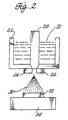
- Figure 2 describes an embodiment wherein an alloy of aluminum with 0.5 weight percent copper, is melted in a crucible 22 with a suitable heating element to produce metal to be used in making a sputtering target.
- the molten metal 20 and crucible 22 comprise part of a liquid dynamic compaction apparatus.
- Atomizing jets 24 and 26 are provided near an opening in the bottom of the crucible 22 and are supplie with a high pressure gas to atomize the metal as it flows through the crucible opening. Th flow of metal through the opening is controlled through a stopper 28.
- the molten metal is atomized into a downwardly directed spray 30, and forms a workpiece 32 as it builds in thickness on a substrate 34.
- the mass flow ratio (ratio between the mass flow rate of the atomizing gas and the mass flow rate of the molten metal), the superheat of the molten metal, the atomizing gas pressure, and the nozzle to substrate spacing must all balance to produce a solid, dense compact rather than a powder.
- the mass flow ratio tends to increase as pressure increases, and grain size will be smaller.
- too high a pressure will cause porosity.
- Lower superheats will tend to require that nozzle to substrate spacings be lowered, and may cause porosity problems as well.
- too high a superheat will make it difficult to extract heat quickly, and grain size will go up.
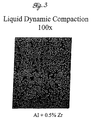
- FIGS. 3 and 4 contrast nicely with the grain sizes obtained by Liquid Dynamic Compaction and by continuous casting methods.
- LDC produces small precipitates and can provide a better dispersion of alloying elements, thus avoiding gross precipitation of alloying elements such as results from continuous casting.
- the above-described atomization process may be used to produce an aluminum-copper workpiece with randomly oriented aluminum-copper alloy grains about ten microns in size, and without dendritic structures visible in these grains at 100 x magnification.
- conventional casting methods produce grains in the millimeter range with a distinct dendritic structure.
- conventionally cast aluminum also tends to have a certain degree of ⁇ 100> texture because this axis tends to align with the heat flow during cooling.
- a workpiece with randomly oriented grains i.e., no texture
- random orientation may be optimum for certain sputtering conditions.
- Workpieces produced in this manner also exhibit few precipitate regions measuring more than one micron. With conventional casting techniques, much larger precipitates of the second phase material are produced.
- LDC is also especially useful in creating sputtering targets with unusual alloy combinations, such as aluminum and titanium, tungsten, tantalum, rhenium, scandium, cobalt, molybdenum, and hafnium, to avoid problems of precipitation from the matrix phase during cooling in conventional casting techniques, or creating precipitate regions too large for use as acceptable sputtering targets.
- the LDC process allows the creation of alloys of these metals with very small precipitates and targets with high concentrations of the alloying elements may thus be created.
- the substrate 34 in FIG. 1 may be moved during preform formation as the atomized metal is being deposited, to control the location of material so that the shape of the preform is closer to that desired in the finished sputtering target (known as "near net shape forming") by avoiding undesirable buildup.
- the preform can be fabricated into a sputtering target of a variety of shapes, annular rings being a common form by fabricating, e.g., machining.
- the as-deposited texture of an LDC preform is random, as evidenced by the orientation distribution function in Figure 5.
- the random texture may provide benefits in the ability of the sputtering target to fill vias and provide good step coverage.
- FIGS. 6, 7 and 8 illustrate the practice to produce material for targets by the ECAE method.
- the process is performed using an apparatus comprising a ram 50 and a ECAE die 70.
- the die includes an inlet channel 72 and an outlet channel 74, transverse but contiguous to inlet channel 72.
- a workpiece, 60 which may comprise a workpiece produced by the LDC process illustrated in connection with FIG. 1, is extruded through the die.
- the preform created by LDC is a substantially square plate 60, e.g., nominally seventeen inches on a side and one inch thick.
- the channels of the steel extrusion die 72 and 74 are of substantially identical cross section as the plate having, in this example, a cross section of seventeen inches by one inch, such that the plate fits tightly when inserted edgewise into the inlet channel 72.
- the outlet channel 74 is contiguous and extends from the inlet channel 72, and is of substantially identical cross section as the first channel. In this example the channels are substantially perpendicular but the channels may be at angles greater than 90°.
- the channels are oriented relative to each other such that upon entry into the inlet channel, the large faces of the workpiece are vertical, and upon exit from the outlet channel, the large faces of the workpiece are horizontal.
- Each channel terminates at the channel intersection such that the two transverse channels form a single contiguous passageway with an "L" shaped longitudinal cross section.
- the workpiece 60 is advantageously lubricated with any known anti-seize lubricant, so that a ram 50 presses the workpiece into the inlet channel 72.
- the ram continues pressing the workpiece, causing it to shear along the plane of intersection of the two channels.
- the workpiece is forced to exit the die through the outlet channel 74, continually shearing along the channel intersection plane as it passes through the intersection.
- the ram is then retracted, and the workpiece is pulled out of the outlet channel.
- the inlet and outlet channels at 90° to each other, the channels may be at other angles.
- the punch pressures required to perform an ECAE extrusion are much less than those required for traditional extrusion techniques, typically the ratio of punch pressure to the flow stress for a 90° angle is 1.
- the extruded workpiece is of the same size and shape as the preform prior to extrusion, there is little or no waste of material such as occurs during extensive area reductions by roll or forge forming.
- the texture can be controlled by varying temperature, rate and number of subsequent repeated ECAE extrusions on the same workpiece. If the workpiece is rotated so that different edges are inserted initially into the ECAE die, the shear plane is oriented differently relative to the workpiece. Thus, by rotating or "flipping" the workpiece prior to some or all re-insertions into the extrusion channel, to perform a predetermined sequence of extrusions, a final extruded product with a particular texture suitable for a particular sputtering target can be obtained. Thus, by changing the sequence of workpiece orientations in subsequent re-extrusions, different textures can be created which are especially suitable for specific target applications.
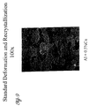
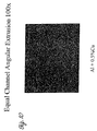
- FIGS. 9 and 10 illustrate the different metallurgical structure achievable by the ECAE process.
- the structure of the standard rolled and crystallized material (FIG. 9) is not nearly as fine or as ordered as the ECAE product (FIG. 10), for the same composition.
- Certain textures are known to be desirable for different purposes. For example, for deposited film thickness uniformity, in the manufacture of aluminum alloy targets with a planar sputtering surface, it has been found that it is desirable to have more grains with ⁇ 200 ⁇ planes approximately parallel to the target sputtering surface than grains with ⁇ 220 ⁇ planes facing or parallel to the target sputtering surface. In contrast, aluminum targets with conical sputtering surfaces have been found to perform better when there are fewer grains with ⁇ 200 ⁇ , planes facing or approximately parallel to the target sputtering surface than grains with ⁇ 220 ⁇ planes facing or parallel to the target sputtering surface. Other desired deposited film characteristics (step coverage, via fill, etc.) will require different textures or even random orientation.
- a determination of material texture is typically made by an X-ray diffraction measurement. These measurements are shown in FIG. 11 for twelve different sets of ECAE extrusions and a sputtering target formed with previously known techniques. Depicted in FIG. 11 are the relative intensities of reflected X-rays corresponding to different grain lattice orientations relative to a workpiece surface. As can be seen, a wide variety of grain orientations are possible.
- Sample 2B exhibits a much stronger ⁇ 220 ⁇ intensity than ⁇ 200 ⁇ .
- sample 2C exhibits a much stronger ⁇ 200 ⁇ intensity than ⁇ 220 ⁇ .
- ⁇ 200 ⁇ intensity is greater than ⁇ 220 ⁇ intensity
- the sample exhibits predominantly ⁇ 200> texture perpendicular to the target surface.
- Strong ⁇ 220> texture is associated with high quality conical aluminum sputtering targets that provide good sputtered film uniformity
- strong ⁇ 200> texture is associated with planar aluminum sputtering targets that provide good sputtered film uniformity.
Landscapes
- Chemical & Material Sciences (AREA)
- Engineering & Computer Science (AREA)
- Mechanical Engineering (AREA)
- Materials Engineering (AREA)
- Metallurgy (AREA)
- Organic Chemistry (AREA)
- Manufacturing & Machinery (AREA)
- Chemical Kinetics & Catalysis (AREA)
- Dispersion Chemistry (AREA)
- Composite Materials (AREA)
- Physical Vapour Deposition (AREA)
- Powder Metallurgy (AREA)
Claims (6)
- Sputter-Target bestehend aus Aluminium und wahlweise bis zu zehn Gewichtsprozent aus zumindest einem Metall ausgewählt aus der Gruppe bestehend aus Kupfer, Silizium, Zirkon, Titan, Wolfram, Tantal, Rhenium, Scandium, Kobalt, Molybdän und Hafnium, bei dem das Aluminium die Form von Körnern mit Abmessungen von weniger als 20 Mikron hat; und das Target ein vorherrschendes <200>- oder <220>-Gefüge senkrecht zur Targetoberfläche hat.
- Target nach Anspruch 1 mit Niederschlagsbereichen, worin die Niederschlagsbereiche Abmessungen von weniger als einem Mikron haben.
- Target nach Anspruch 1, worin die Aluminiumkörner Abmessungen von weniger als 2 Mikron haben.
- Target nach Anspruch 1, aufweisend bis zu zehn Gewichtsprozent zumindest eines Metalls ausgewählt aus der Gruppe bestehend aus Kupfer, Silizium, Zirkon, Titan, Wolfram, Tantal, Rhenium, Scandium, Kobalt, Molybdän und Hafnium.
- Target nach Anspruch 4 mit Niederschlagsbereichen, worin die Niederschlagsbereiche Abmessungen von weniger als einem Mikron haben.
- Sputter-Target nach Anspruch 4, worin die Aluminiumkörner Abmessungen von weniger als 2 Mikron haben.
Applications Claiming Priority (3)
| Application Number | Priority Date | Filing Date | Title |
|---|---|---|---|
| US363397 | 1994-12-23 | ||
| US08/363,397 US5590389A (en) | 1994-12-23 | 1994-12-23 | Sputtering target with ultra-fine, oriented grains and method of making same |
| EP95944653A EP0746436B1 (de) | 1994-12-23 | 1995-12-22 | Sputter-target mit ultrafeinen orientierten körnern und verfahren zu deren herstellung |
Related Parent Applications (1)
| Application Number | Title | Priority Date | Filing Date |
|---|---|---|---|
| EP95944653A Division EP0746436B1 (de) | 1994-12-23 | 1995-12-22 | Sputter-target mit ultrafeinen orientierten körnern und verfahren zu deren herstellung |
Publications (3)
| Publication Number | Publication Date |
|---|---|
| EP1053810A2 EP1053810A2 (de) | 2000-11-22 |
| EP1053810A3 EP1053810A3 (de) | 2000-11-29 |
| EP1053810B1 true EP1053810B1 (de) | 2004-02-25 |
Family
ID=23430046
Family Applications (2)
| Application Number | Title | Priority Date | Filing Date |
|---|---|---|---|
| EP95944653A Expired - Lifetime EP0746436B1 (de) | 1994-12-23 | 1995-12-22 | Sputter-target mit ultrafeinen orientierten körnern und verfahren zu deren herstellung |
| EP00118588A Expired - Lifetime EP1053810B1 (de) | 1994-12-23 | 1995-12-22 | Target für die Kathodenzerstäubung mit ultrafeinen orienterten Körnern |
Family Applications Before (1)
| Application Number | Title | Priority Date | Filing Date |
|---|---|---|---|
| EP95944653A Expired - Lifetime EP0746436B1 (de) | 1994-12-23 | 1995-12-22 | Sputter-target mit ultrafeinen orientierten körnern und verfahren zu deren herstellung |
Country Status (6)
| Country | Link |
|---|---|
| US (3) | US5590389A (de) |
| EP (2) | EP0746436B1 (de) |
| JP (1) | JP3597539B2 (de) |
| KR (1) | KR100217484B1 (de) |
| DE (2) | DE69526649T2 (de) |
| WO (1) | WO1996020055A1 (de) |
Cited By (1)
| Publication number | Priority date | Publication date | Assignee | Title |
|---|---|---|---|---|
| CN106734297A (zh) * | 2016-11-24 | 2017-05-31 | 上海电机学院 | 钛废弃切屑再制造的t型通道挤压固化方法 |
Families Citing this family (79)
| Publication number | Priority date | Publication date | Assignee | Title |
|---|---|---|---|---|
| US5500301A (en) * | 1991-03-07 | 1996-03-19 | Kabushiki Kaisha Kobe Seiko Sho | A1 alloy films and melting A1 alloy sputtering targets for depositing A1 alloy films |
| US5590389A (en) * | 1994-12-23 | 1996-12-31 | Johnson Matthey Electronics, Inc. | Sputtering target with ultra-fine, oriented grains and method of making same |
| FR2756572B1 (fr) * | 1996-12-04 | 1999-01-08 | Pechiney Aluminium | Alliages d'aluminium a temperature de recristallisation elevee utilisee dans les cibles de pulverisation cathodiques |
| JP3365954B2 (ja) * | 1997-04-14 | 2003-01-14 | 株式会社神戸製鋼所 | 半導体電極用Al−Ni−Y 合金薄膜および半導体電極用Al−Ni−Y 合金薄膜形成用スパッタリングターゲット |
| US6569270B2 (en) | 1997-07-11 | 2003-05-27 | Honeywell International Inc. | Process for producing a metal article |
| US6139701A (en) * | 1997-11-26 | 2000-10-31 | Applied Materials, Inc. | Copper target for sputter deposition |
| US6315872B1 (en) | 1997-11-26 | 2001-11-13 | Applied Materials, Inc. | Coil for sputter deposition |
| US6001227A (en) * | 1997-11-26 | 1999-12-14 | Applied Materials, Inc. | Target for use in magnetron sputtering of aluminum for forming metallization films having low defect densities and methods for manufacturing and using such target |
| US6348139B1 (en) | 1998-06-17 | 2002-02-19 | Honeywell International Inc. | Tantalum-comprising articles |
| US6348113B1 (en) | 1998-11-25 | 2002-02-19 | Cabot Corporation | High purity tantalum, products containing the same, and methods of making the same |
| US6113761A (en) | 1999-06-02 | 2000-09-05 | Johnson Matthey Electronics, Inc. | Copper sputtering target assembly and method of making same |
| US6858102B1 (en) | 2000-11-15 | 2005-02-22 | Honeywell International Inc. | Copper-containing sputtering targets, and methods of forming copper-containing sputtering targets |
| US6521173B2 (en) * | 1999-08-19 | 2003-02-18 | H.C. Starck, Inc. | Low oxygen refractory metal powder for powder metallurgy |
| US6432819B1 (en) | 1999-09-27 | 2002-08-13 | Applied Materials, Inc. | Method and apparatus of forming a sputtered doped seed layer |
| US6391163B1 (en) | 1999-09-27 | 2002-05-21 | Applied Materials, Inc. | Method of enhancing hardness of sputter deposited copper films |
| US6423161B1 (en) * | 1999-10-15 | 2002-07-23 | Honeywell International Inc. | High purity aluminum materials |
| JP2003529206A (ja) * | 1999-11-24 | 2003-09-30 | ハネウェル・インターナショナル・インコーポレーテッド | 物理蒸着ターゲット、導電性集積回路金属合金相互接続配線、電気めっきアノード、集積回路における導電性相互接続配線として用いるための金属合金 |
| US20040072009A1 (en) * | 1999-12-16 | 2004-04-15 | Segal Vladimir M. | Copper sputtering targets and methods of forming copper sputtering targets |
| US6878250B1 (en) * | 1999-12-16 | 2005-04-12 | Honeywell International Inc. | Sputtering targets formed from cast materials |
| US6780794B2 (en) * | 2000-01-20 | 2004-08-24 | Honeywell International Inc. | Methods of bonding physical vapor deposition target materials to backing plate materials |
| US7517417B2 (en) * | 2000-02-02 | 2009-04-14 | Honeywell International Inc. | Tantalum PVD component producing methods |
| US6331233B1 (en) | 2000-02-02 | 2001-12-18 | Honeywell International Inc. | Tantalum sputtering target with fine grains and uniform texture and method of manufacture |
| US6698647B1 (en) | 2000-03-10 | 2004-03-02 | Honeywell International Inc. | Aluminum-comprising target/backing plate structures |
| US6399215B1 (en) | 2000-03-28 | 2002-06-04 | The Regents Of The University Of California | Ultrafine-grained titanium for medical implants |
| US20010047838A1 (en) * | 2000-03-28 | 2001-12-06 | Segal Vladimir M. | Methods of forming aluminum-comprising physical vapor deposition targets; sputtered films; and target constructions |
| DE10017414A1 (de) * | 2000-04-07 | 2001-10-11 | Unaxis Materials Deutschland G | Sputtertarget auf der Basis eines Metalls oder einer Metalllegierung und Verfahren zu dessen Herstellung |
| US6197129B1 (en) * | 2000-05-04 | 2001-03-06 | The United States Of America As Represented By The United States Department Of Energy | Method for producing ultrafine-grained materials using repetitive corrugation and straightening |
| EP1287172B1 (de) * | 2000-05-22 | 2008-10-29 | Cabot Corporation | Hochreines niobmetall und erzeugnisse daraus und verfahren zu dessen herstellung |
| AU2001265309A1 (en) * | 2000-06-02 | 2001-12-17 | Honeywell International, Inc. | Fine grain size material, sputtering target, methods of forming, and micro-arc reduction method |
| AU6512601A (en) * | 2000-06-02 | 2001-12-17 | Honeywell Int Inc | Sputtering method, apparatus, and target for reduced arcing |
| US7041204B1 (en) * | 2000-10-27 | 2006-05-09 | Honeywell International Inc. | Physical vapor deposition components and methods of formation |
| US6946039B1 (en) * | 2000-11-02 | 2005-09-20 | Honeywell International Inc. | Physical vapor deposition targets, and methods of fabricating metallic materials |
| DE60214683T2 (de) * | 2001-02-20 | 2007-09-13 | H.C. Starck, Inc., Newton | Platten aus refraktärem metall mit einheitlicher textur und verfahren zu ihrer herstellung |
| JP2004520492A (ja) * | 2001-05-01 | 2004-07-08 | ハネウェル・インターナショナル・インコーポレーテッド | Ti及びZrを含む物理的蒸着ターゲット、及び使用方法 |
| CN1289709C (zh) * | 2001-08-13 | 2006-12-13 | 贝卡尔特股份有限公司 | 用于制造溅射靶的方法 |
| US7081148B2 (en) * | 2001-09-18 | 2006-07-25 | Praxair S.T. Technology, Inc. | Textured-grain-powder metallurgy tantalum sputter target |
| US6770154B2 (en) * | 2001-09-18 | 2004-08-03 | Praxair S.T. Technology, Inc. | Textured-grain-powder metallurgy tantalum sputter target |
| JP2003105468A (ja) * | 2001-09-25 | 2003-04-09 | Furukawa Electric Co Ltd:The | 端子用アルミニウム合金材料および前記材料からなる端子 |
| US6605199B2 (en) * | 2001-11-14 | 2003-08-12 | Praxair S.T. Technology, Inc. | Textured-metastable aluminum alloy sputter targets and method of manufacture |
| WO2003044246A1 (en) * | 2001-11-16 | 2003-05-30 | Honeywell International Inc. | Anodes for electroplating operations, and methods of forming materials over semiconductor substrates |
| US6883359B1 (en) * | 2001-12-20 | 2005-04-26 | The Texas A&M University System | Equal channel angular extrusion method |
| US6976380B1 (en) | 2002-01-24 | 2005-12-20 | The Texas A&M University System | Developing the texture of a material |
| US20040129559A1 (en) * | 2002-04-12 | 2004-07-08 | Misner Josh W. | Diffusion bonded assemblies and fabrication methods |
| ES2224787B1 (es) * | 2002-05-13 | 2006-02-01 | Universidad Publica De Navarra | Procesado continuo de materiales metalicos mediante deformacion plastica en canal poliangular. |
| US20040256218A1 (en) * | 2002-05-31 | 2004-12-23 | Glass Howard L. | Thin films and methods of forming thin films utilizing ECAE-targets |
| US6895795B1 (en) | 2002-06-26 | 2005-05-24 | General Dynamics Ots (Garland), L.P. | Continuous severe plastic deformation process for metallic materials |
| US20040016635A1 (en) * | 2002-07-19 | 2004-01-29 | Ford Robert B. | Monolithic sputtering target assembly |
| JP4526758B2 (ja) * | 2002-09-11 | 2010-08-18 | 日鉱金属株式会社 | 珪化鉄粉末及びその製造方法 |
| JP4388263B2 (ja) * | 2002-09-11 | 2009-12-24 | 日鉱金属株式会社 | 珪化鉄スパッタリングターゲット及びその製造方法 |
| EP2213763A3 (de) * | 2003-08-11 | 2010-08-18 | Honeywell International Inc. | Target-/Trägerplattenkonstruktionen und Verfahren zur Herstellung von Target-/Trägerplattenkonstruktionen |
| EP1656467A2 (de) * | 2003-08-21 | 2006-05-17 | Honeywell International Inc. | Kupferhaltige pvd-targets und herstellungsverfahren dafür |
| CN1871372B (zh) * | 2003-11-06 | 2010-11-17 | 日矿金属株式会社 | 钽溅射靶 |
| US8252126B2 (en) * | 2004-05-06 | 2012-08-28 | Global Advanced Metals, Usa, Inc. | Sputter targets and methods of forming same by rotary axial forging |
| KR100607106B1 (ko) * | 2004-11-29 | 2006-08-02 | 한국과학기술연구원 | 소재의 두께를 균일하게 제어하는 연속 전단가공 장치 |
| DE102005003445B4 (de) * | 2005-01-21 | 2009-06-04 | H.C. Starck Hermsdorf Gmbh | Metallsubstrat-Werkstoff für die Anodenteller von Drehanodenröntgenröhren, Verfahren zur Herstellung eines solchen Werkstoffes sowie Verfahren zur Herstellung eines Anodentellers unter Verwendung eines solchen Werkstoffes |
| US20060201589A1 (en) * | 2005-03-11 | 2006-09-14 | Honeywell International Inc. | Components comprising metallic material, physical vapor deposition targets, thin films, and methods of forming metallic components |
| KR100734811B1 (ko) * | 2005-09-16 | 2007-07-03 | 한국기초과학지원연구원 | 고품질의 대면적 글래시 산화물 타겟의 제조방법 및 그제조방법에 의한 타겟 |
| US20070074970A1 (en) * | 2005-09-20 | 2007-04-05 | Cp Technologies, Inc. | Device and method of manufacturing sputtering targets |
| US20070084527A1 (en) * | 2005-10-19 | 2007-04-19 | Stephane Ferrasse | High-strength mechanical and structural components, and methods of making high-strength components |
| US7935382B2 (en) * | 2005-12-20 | 2011-05-03 | Momentive Performance Materials, Inc. | Method for making crystalline composition |
| US20070169853A1 (en) * | 2006-01-23 | 2007-07-26 | Heraeus, Inc. | Magnetic sputter targets manufactured using directional solidification |
| US20070251819A1 (en) * | 2006-05-01 | 2007-11-01 | Kardokus Janine K | Hollow cathode magnetron sputtering targets and methods of forming hollow cathode magnetron sputtering targets |
| US20070251818A1 (en) * | 2006-05-01 | 2007-11-01 | Wuwen Yi | Copper physical vapor deposition targets and methods of making copper physical vapor deposition targets |
| TW200811304A (en) * | 2006-07-17 | 2008-03-01 | Howmet Corp | Method of making sputtering target and target produced |
| US8702919B2 (en) | 2007-08-13 | 2014-04-22 | Honeywell International Inc. | Target designs and related methods for coupled target assemblies, methods of production and uses thereof |
| WO2010051040A1 (en) * | 2008-11-03 | 2010-05-06 | Tosoh Smd, Inc. | Method of making a sputter target and sputter targets made thereby |
| JP5685201B2 (ja) | 2009-01-22 | 2015-03-18 | トーソー エスエムディー,インク. | 一体構造のアルミニウム合金ターゲットとそれを製造する方法 |
| US9142226B2 (en) | 2012-06-29 | 2015-09-22 | Seagate Technology Llc | Thin film with tuned grain size |
| US9034150B2 (en) | 2012-11-29 | 2015-05-19 | Seagate Technology Llc | Thin film with tuned anisotropy and magnetic moment |
| US20140271336A1 (en) | 2013-03-15 | 2014-09-18 | Crs Holdings Inc. | Nanostructured Titanium Alloy And Method For Thermomechanically Processing The Same |
| RU2534324C1 (ru) * | 2013-10-11 | 2014-11-27 | Федеральное государственное бюджетное учреждение науки Институт физики прочности и материаловедения Сибирского отделения Российской академии наук (ИФПМ СО РАН) | Способ изготовления композиционного катода для нанесения многокомпонентных ионно-плазменных покрытий |
| JP5828350B2 (ja) * | 2014-04-11 | 2015-12-02 | 三菱マテリアル株式会社 | 円筒型スパッタリングターゲット用素材の製造方法 |
| US9378760B2 (en) | 2014-07-31 | 2016-06-28 | Seagate Technology Llc | Data reader with tuned microstructure |
| US11359273B2 (en) | 2015-08-03 | 2022-06-14 | Honeywell International Inc. | Frictionless forged aluminum alloy sputtering target with improved properties |
| US10900102B2 (en) | 2016-09-30 | 2021-01-26 | Honeywell International Inc. | High strength aluminum alloy backing plate and methods of making |
| CN108866489B (zh) * | 2017-05-16 | 2020-05-19 | 中国科学院金属研究所 | 一种具有抗菌功能的钛合金纳米涂层及其制备方法 |
| US11062889B2 (en) | 2017-06-26 | 2021-07-13 | Tosoh Smd, Inc. | Method of production of uniform metal plates and sputtering targets made thereby |
| JP2019173048A (ja) * | 2018-03-26 | 2019-10-10 | Jx金属株式会社 | スパッタリングターゲット部材及びその製造方法 |
| CN111266586A (zh) * | 2020-03-02 | 2020-06-12 | 合肥尚德新材料有限公司 | 一种制备大尺寸高致密度含稀土ito铝靶材的方法 |
Family Cites Families (22)
| Publication number | Priority date | Publication date | Assignee | Title |
|---|---|---|---|---|
| US4016738A (en) * | 1976-04-27 | 1977-04-12 | Alexandr Vladimirovich Puchko | Traverse wedge forming machine |
| US4198283A (en) * | 1978-11-06 | 1980-04-15 | Materials Research Corporation | Magnetron sputtering target and cathode assembly |
| JPH0796701B2 (ja) * | 1984-12-12 | 1995-10-18 | 日立金属株式会社 | スパッタ用ターゲットとその製造方法 |
| US4971674A (en) * | 1986-08-06 | 1990-11-20 | Ube Industries, Ltd. | Magnetron sputtering method and apparatus |
| US4961831A (en) * | 1986-12-23 | 1990-10-09 | Balzers Aktiengesellschaft | Composite material having a slide layer applied by cathode sputtering |
| ATE80671T1 (de) * | 1986-12-23 | 1992-10-15 | Balzers Hochvakuum | Verbundwerkstoff mit einer durch kathodenzerstaeubung aufgebrachten gleitschicht. |
| JPS63216966A (ja) * | 1987-03-06 | 1988-09-09 | Toshiba Corp | スパツタタ−ゲツト |
| JPS63241164A (ja) * | 1987-03-30 | 1988-10-06 | Toshiba Corp | スパッタリングターゲットおよび電気配線用合金膜 |
| US4963239A (en) * | 1988-01-29 | 1990-10-16 | Hitachi, Ltd. | Sputtering process and an apparatus for carrying out the same |
| US4964968A (en) * | 1988-04-30 | 1990-10-23 | Mitsubishi Kasei Corp. | Magnetron sputtering apparatus |
| JPH01290765A (ja) * | 1988-05-16 | 1989-11-22 | Toshiba Corp | スパッタリングターゲット |
| US4964962A (en) * | 1988-10-08 | 1990-10-23 | Matsushita Electric Works, Ltd. | Method for forming conducting metal layer on inorganic substrate |
| US4961832A (en) * | 1989-03-14 | 1990-10-09 | Shagun Vladimir A | Apparatus for applying film coatings onto substrates in vacuum |
| JP2712561B2 (ja) * | 1989-05-26 | 1998-02-16 | 住友化学工業株式会社 | スパッタリング用アルミニウムターゲット |
| JPH0313570A (ja) * | 1989-06-09 | 1991-01-22 | Mitsubishi Electric Corp | 半導体製造装置及び半導体製造装置用ターゲット |
| JPH0371510A (ja) * | 1989-08-10 | 1991-03-27 | Showa Denko Kk | 透明導電膜 |
| WO1992001080A1 (en) * | 1990-07-03 | 1992-01-23 | Tosoh Smd, Inc. | Improved sputter target for coating compact discs, methods of use thereof, and methods of manufacture of the targets |
| JP2934714B2 (ja) * | 1990-08-22 | 1999-08-16 | カシオ計算機株式会社 | 合金薄膜の形成方法 |
| US5087297A (en) * | 1991-01-17 | 1992-02-11 | Johnson Matthey Inc. | Aluminum target for magnetron sputtering and method of making same |
| US5400633A (en) * | 1993-09-03 | 1995-03-28 | The Texas A&M University System | Apparatus and method for deformation processing of metals, ceramics, plastics and other materials |
| JP3002369U (ja) | 1994-03-25 | 1994-09-20 | ホン シェン ウェイ | 三脚スタンドの固定構造 |
| US5590389A (en) * | 1994-12-23 | 1996-12-31 | Johnson Matthey Electronics, Inc. | Sputtering target with ultra-fine, oriented grains and method of making same |
-
1994
- 1994-12-23 US US08/363,397 patent/US5590389A/en not_active Expired - Lifetime
-
1995
- 1995-10-30 US US08/544,970 patent/US5809393A/en not_active Expired - Fee Related
- 1995-10-30 US US08/544,971 patent/US5780755A/en not_active Expired - Lifetime
- 1995-12-22 EP EP95944653A patent/EP0746436B1/de not_active Expired - Lifetime
- 1995-12-22 WO PCT/US1995/016794 patent/WO1996020055A1/en not_active Ceased
- 1995-12-22 JP JP52055496A patent/JP3597539B2/ja not_active Expired - Fee Related
- 1995-12-22 KR KR1019960704629A patent/KR100217484B1/ko not_active Expired - Fee Related
- 1995-12-22 EP EP00118588A patent/EP1053810B1/de not_active Expired - Lifetime
- 1995-12-22 DE DE69526649T patent/DE69526649T2/de not_active Expired - Lifetime
- 1995-12-22 DE DE69532617T patent/DE69532617T2/de not_active Expired - Lifetime
Cited By (1)
| Publication number | Priority date | Publication date | Assignee | Title |
|---|---|---|---|---|
| CN106734297A (zh) * | 2016-11-24 | 2017-05-31 | 上海电机学院 | 钛废弃切屑再制造的t型通道挤压固化方法 |
Also Published As
| Publication number | Publication date |
|---|---|
| EP0746436A4 (de) | 1997-05-07 |
| WO1996020055A1 (en) | 1996-07-04 |
| US5780755A (en) | 1998-07-14 |
| EP0746436B1 (de) | 2002-05-08 |
| DE69532617D1 (de) | 2004-04-01 |
| EP0746436A1 (de) | 1996-12-11 |
| DE69532617T2 (de) | 2005-02-03 |
| EP1053810A2 (de) | 2000-11-22 |
| KR100217484B1 (ko) | 1999-09-01 |
| DE69526649D1 (de) | 2002-06-13 |
| JP3597539B2 (ja) | 2004-12-08 |
| US5590389A (en) | 1996-12-31 |
| EP1053810A3 (de) | 2000-11-29 |
| US5809393A (en) | 1998-09-15 |
| DE69526649T2 (de) | 2002-12-05 |
| KR970701113A (ko) | 1997-03-17 |
| JPH09509985A (ja) | 1997-10-07 |
Similar Documents
| Publication | Publication Date | Title |
|---|---|---|
| EP0746436B1 (de) | Sputter-target mit ultrafeinen orientierten körnern und verfahren zu deren herstellung | |
| WO1996020055A9 (en) | Sputtering target with ultra-fine, oriented grains and method of making same | |
| KR100512295B1 (ko) | 미세균일 구조 및 조직을 갖는 금속재 및 그 제조방법 | |
| KR100528090B1 (ko) | 미세한 균일 구조 및 조직을 가지는 금속 물품 및 그의 제조방법 | |
| US20030052000A1 (en) | Fine grain size material, sputtering target, methods of forming, and micro-arc reduction method | |
| EP2172292B1 (de) | Verfahren zur Herstellung von losen Metallstrukturen mit submikrongroßen Körnern und mit diesem Verfahren hergestellte Strukturen | |
| TWI484054B (zh) | 濺鍍靶及藉由旋轉軸鍛造製造彼等之方法 | |
| CN102513353B (zh) | 溅射靶及制造方法 | |
| EP2065480B1 (de) | Rohrförmige Molybdän-Sputter-Targets mit einheitlicher Korn-Größe und -Textur | |
| EP2185300B1 (de) | Refraktäre metallplatten mit verbesserter texturgleichmässigkeit | |
| DE102008034145B4 (de) | Sputtertarget aus einer Legierung auf Al-Basis des Al-Ni-La-Si- Systems und Verfahren zu dessen Herstellung | |
| EP1242645A2 (de) | Target für die kathodenzerstäubung und verfahren zur herstellung eines solchen targets | |
| EP2166128B1 (de) | Verfahren zum Herstellen von Metalloxidschichten durch Funkenverdampfung | |
| EP1337682A2 (de) | Pvd-targets und verfahren zur herstellung metallischer materialien | |
| EP1444376B1 (de) | Hochreine aluminium-sputtertargets | |
| CN115415351B (zh) | 一种高纯铜靶材的制备方法及靶材的用途 | |
| WO2001094660A2 (en) | Sputtering target | |
| US20210310102A1 (en) | Aluminum alloy material and method for producing aluminum alloy material | |
| Duszczyk et al. | Properties of particles produced by different rapid solidification techniques | |
| TWI824162B (zh) | 從熱擠壓程序生產用於藉由濺射法的薄膜塗覆技術之銅靶之方法 | |
| WO2025168349A1 (de) | Taal-target | |
| TW202540463A (zh) | 具有改善的性能及可預測性之鉭濺射靶及其製造方法 |
Legal Events
| Date | Code | Title | Description |
|---|---|---|---|
| PUAI | Public reference made under article 153(3) epc to a published international application that has entered the european phase |
Free format text: ORIGINAL CODE: 0009012 |
|
| PUAL | Search report despatched |
Free format text: ORIGINAL CODE: 0009013 |
|
| 17P | Request for examination filed |
Effective date: 20000828 |
|
| AC | Divisional application: reference to earlier application |
Ref document number: 746436 Country of ref document: EP |
|
| AK | Designated contracting states |
Kind code of ref document: A2 Designated state(s): DE FR GB IE |
|
| AK | Designated contracting states |
Kind code of ref document: A3 Designated state(s): DE FR GB IE |
|
| RIN1 | Information on inventor provided before grant (corrected) |
Inventor name: EMIGH, ROGER ALAN Inventor name: KARDOKUS, JANINE KIYABU Inventor name: DUNLOP, JOHN ALDEN Inventor name: YUAN, JUN |
|
| AKX | Designation fees paid |
Free format text: DE FR GB IE |
|
| 17Q | First examination report despatched |
Effective date: 20020628 |
|
| GRAH | Despatch of communication of intention to grant a patent |
Free format text: ORIGINAL CODE: EPIDOS IGRA |
|
| GRAS | Grant fee paid |
Free format text: ORIGINAL CODE: EPIDOSNIGR3 |
|
| GRAA | (expected) grant |
Free format text: ORIGINAL CODE: 0009210 |
|
| RTI1 | Title (correction) |
Free format text: SPUTTERING TARGET WITH ULTRAFINE ORIENTED GRAINS |
|
| AC | Divisional application: reference to earlier application |
Ref document number: 0746436 Country of ref document: EP Kind code of ref document: P |
|
| AK | Designated contracting states |
Kind code of ref document: B1 Designated state(s): DE FR GB IE |
|
| REG | Reference to a national code |
Ref country code: GB Ref legal event code: FG4D |
|
| REG | Reference to a national code |
Ref country code: IE Ref legal event code: FG4D |
|
| REF | Corresponds to: |
Ref document number: 69532617 Country of ref document: DE Date of ref document: 20040401 Kind code of ref document: P |
|
| ET | Fr: translation filed | ||
| PG25 | Lapsed in a contracting state [announced via postgrant information from national office to epo] |
Ref country code: IE Free format text: LAPSE BECAUSE OF NON-PAYMENT OF DUE FEES Effective date: 20041222 |
|
| PLBE | No opposition filed within time limit |
Free format text: ORIGINAL CODE: 0009261 |
|
| STAA | Information on the status of an ep patent application or granted ep patent |
Free format text: STATUS: NO OPPOSITION FILED WITHIN TIME LIMIT |
|
| 26N | No opposition filed |
Effective date: 20041126 |
|
| REG | Reference to a national code |
Ref country code: IE Ref legal event code: MM4A |
|
| PGFP | Annual fee paid to national office [announced via postgrant information from national office to epo] |
Ref country code: GB Payment date: 20051104 Year of fee payment: 11 |
|
| GBPC | Gb: european patent ceased through non-payment of renewal fee |
Effective date: 20061222 |
|
| PG25 | Lapsed in a contracting state [announced via postgrant information from national office to epo] |
Ref country code: GB Free format text: LAPSE BECAUSE OF NON-PAYMENT OF DUE FEES Effective date: 20061222 |
|
| PGFP | Annual fee paid to national office [announced via postgrant information from national office to epo] |
Ref country code: FR Payment date: 20101203 Year of fee payment: 16 |
|
| PGFP | Annual fee paid to national office [announced via postgrant information from national office to epo] |
Ref country code: DE Payment date: 20101230 Year of fee payment: 16 |
|
| REG | Reference to a national code |
Ref country code: FR Ref legal event code: ST Effective date: 20120831 |
|
| PG25 | Lapsed in a contracting state [announced via postgrant information from national office to epo] |
Ref country code: DE Free format text: LAPSE BECAUSE OF NON-PAYMENT OF DUE FEES Effective date: 20120703 |
|
| REG | Reference to a national code |
Ref country code: DE Ref legal event code: R119 Ref document number: 69532617 Country of ref document: DE Effective date: 20120703 |
|
| PG25 | Lapsed in a contracting state [announced via postgrant information from national office to epo] |
Ref country code: FR Free format text: LAPSE BECAUSE OF NON-PAYMENT OF DUE FEES Effective date: 20120102 |