EP1053828B1 - Verfahren und Vorrichtung zum Abrichten eines Poliertuches - Google Patents
Verfahren und Vorrichtung zum Abrichten eines Poliertuches Download PDFInfo
- Publication number
- EP1053828B1 EP1053828B1 EP00113403A EP00113403A EP1053828B1 EP 1053828 B1 EP1053828 B1 EP 1053828B1 EP 00113403 A EP00113403 A EP 00113403A EP 00113403 A EP00113403 A EP 00113403A EP 1053828 B1 EP1053828 B1 EP 1053828B1
- Authority
- EP
- European Patent Office
- Prior art keywords
- polishing
- polishing cloth
- dresser
- turntable
- rotational speed
- Prior art date
- Legal status (The legal status is an assumption and is not a legal conclusion. Google has not performed a legal analysis and makes no representation as to the accuracy of the status listed.)
- Expired - Lifetime
Links
Images




Classifications
-
- B—PERFORMING OPERATIONS; TRANSPORTING
- B24—GRINDING; POLISHING
- B24B—MACHINES, DEVICES, OR PROCESSES FOR GRINDING OR POLISHING; DRESSING OR CONDITIONING OF ABRADING SURFACES; FEEDING OF GRINDING, POLISHING, OR LAPPING AGENTS
- B24B53/00—Devices or means for dressing or conditioning abrasive surfaces
- B24B53/017—Devices or means for dressing, cleaning or otherwise conditioning lapping tools
-
- B—PERFORMING OPERATIONS; TRANSPORTING
- B24—GRINDING; POLISHING
- B24B—MACHINES, DEVICES, OR PROCESSES FOR GRINDING OR POLISHING; DRESSING OR CONDITIONING OF ABRADING SURFACES; FEEDING OF GRINDING, POLISHING, OR LAPPING AGENTS
- B24B37/00—Lapping machines or devices; Accessories
- B24B37/005—Control means for lapping machines or devices
-
- B—PERFORMING OPERATIONS; TRANSPORTING
- B24—GRINDING; POLISHING
- B24B—MACHINES, DEVICES, OR PROCESSES FOR GRINDING OR POLISHING; DRESSING OR CONDITIONING OF ABRADING SURFACES; FEEDING OF GRINDING, POLISHING, OR LAPPING AGENTS
- B24B49/00—Measuring or gauging equipment for controlling the feed movement of the grinding tool or work; Arrangements of indicating or measuring equipment, e.g. for indicating the start of the grinding operation
Definitions
- the present invention relates to a method and apparatus for dressing a polishing cloth, and more particularly to a method and apparatus for dressing a polishing cloth for restoring polishing capability of the polishing cloth in a polishing apparatus for polishing a workpiece such as a semiconductor wafer having a device pattern thereon to a flat mirror finish by bringing the surface of the workpiece into contact with a surface of the polishing cloth.
- CMP Chemical Mechanical Polishing
- a polishing apparatus has a turntable and a top ring which rotate at respective individual speeds.
- a polishing cloth is attached to the upper surface of the turntable.
- a semiconductor wafer to be polished is placed on the polishing cloth and clamped between the top ring and the turntable.
- An abrasive liquid containing abrasive grains is supplied onto the polishing cloth and retained on the polishing cloth.
- the top ring exerts a certain pressure on the turntable, and the surface of the semiconductor wafer held against the polishing cloth is therefore polished to a flat mirror finish while the top ring and the turntable are rotating.
- a nonwoven fabric cloth is often used as a polishing cloth for polishing the semiconductor wafer having a device pattern thereon.
- polishing cloth After, for example, one or more semiconductor wafers have been polished by bringing the semiconductor wafer in sliding contact with the polishing cloth and rotating the turntable, abrasive grains in the abrasive liquid or ground-off particles of the semiconductor wafer are attached to the polishing cloth. In case of the nonwoven fabric cloth, the polishing cloth is napped.
- the polishing cloth is processed to recover its original polishing capability by a dressing process.
- the dressing process is classified into two processes, one of which is a process for raising the napped polishing cloth by a blush, water jet or gas jet and washing out the remaining abrasive grains or the ground-off particles from the polishing cloth, and the other of which is a process for scraping off a surface of the polishing cloth by diamond or SiC to create a new surface of the polishing cloth.
- the former case even if the dressing is not uniformly performed over the entire dressing area of the polishing cloth, the polished surface of the semiconductor wafer is not greatly affected by the thus dressed polishing cloth. However, in the latter case, the polished surface of the semiconductor wafer is greatly affected by the polishing cloth which has been nonuniformly dressed.
- the polishing apparatus having a diamond grain dresser comprises a top ring for holding the semiconductor wafer and pressing the semiconductor wafer against a polishing cloth on a turntable, and a dresser for dressing the surface of the polishing cloth, and the top ring and the dresser are supported by respective heads.
- the dresser is connected to a motor provided on the dresser head. The dresser is pressed against the surface of the polishing cloth while the dresser is rotated about its central axis and the dresser head is swung, thereby dressing a certain area of the polishing cloth which is to be used for polishing.
- the dressing of the polishing cloth is performed by rotating the turntable, pressing the rotating dresser against the polishing cloth, and moving the dresser radially of the polishing cloth by swinging the dresser head.
- the rotational speed of the dresser is equal to the rotational speed of the turntable.
- the polishing cloth is dressed by the diamond grain dresser, the polishing cloth is slightly scraped off. Unless the polishing cloth is uniformly scraped off in any vertical cross section, i.e., is uniformly scraped off in a radial direction of the polishing cloth, the semiconductor wafer which is a workpiece to be polished cannot be uniformly polished as the number of dressing processes increases. It is confirmed by the inventors of the present application that when the dressing is performed in such a manner that the rotational speed of the dresser is equal to the rotational speed of the turntable, the amount of material removed from the inner circumferential region of the polishing cloth is greater than the amount of material removed from the outer circumferential region of the polishing cloth.
- FIG. 6 shows measurements of the removal amount of material in the polishing cloth which has been dressed by the conventional dressing method.
- the horizontal axis represents a distance from a center of rotation, i.e., a radius (cm) of the polishing cloth, and the vertical axis represents the amount of material removed from the polishing cloth which is expressed by a removal thickness (mm) of material.
- FIG. 6 shows measurements of the removal thickness when the rotational speeds of the dresser and the turntable were the same and about 500 semiconductor wafers were polished on the polishing cloth and the corresponding number of dressing processes were applied to the polishing cloth. Two kinds of diamond grain sizes were used in the experiment.
- the rotational speed of the turntable was 13 rpm and the rotational speed of the dresser was 13 rpm, and 500 semiconductor wafers were polished on the polishing cloth made of polyurethane form and the corresponding number of the dressing processes were applied to the polishing cloth.
- the difference in a removal thickness of material between the outer circumferential region and the inner circumferential region of the polishing cloth was about 100 ⁇ m.
- US 5,456,627A discloses a polishing apparatus for polishing a surface of a workpiece, comprising:
- US 5,486,131A discloses a device for conditioning the surface of a polishing pad.
- Said device provides for a rigid carrier element carrying cutting means on its bottom surface and which is adapted for vertical movement into and out of engagement with the surface of a polishing pad.
- US 4,984,390 discloses a grinding disc dressing apparatus with a rotary dresser for use in a grinding machine.
- a polishing apparatus for polishing a surface of a workpiece as set forth in claim 1 and a polishing method for polishing a surface of a workpiece as set forth in claim 4 is provided.
- Preferred embodiments of the invention are disclosed in the dependent claims.
- a dressing apparatus is installed in a polishing apparatus in FIG. 1.
- the polishing apparatus comprises a turntable 20, and a top ring 3 positioned above the turntable 20 for holding a semiconductor wafer 2 and pressing the semiconductor wafer 2 against the turntable 20.
- the turntable 20 is coupled to a motor 7 and is rotatable about its own axis as indicated by an arrow.
- a polishing cloth 4 (for example, IC-1000 manufactured by Rodel Products Corporation) is mounted on the upper surface of the turntable 20.
- the top ring 3 is coupled to a motor and also to a lifting/lowering cylinder (not shown).
- the top ring 3 is vertically movable and rotatable about its own axis as indicated by arrows by the motor and the lifting/lowering cylinder.
- the top ring 3 can therefore press the semiconductor wafer 2 against the polishing cloth 4 under a desired pressure.
- the semiconductor wafer 2 is attached to a lower surface of the top ring 3 under a vacuum or the like.
- a guide ring 6 is mounted on the outer circumferential edge of the lower surface of the top ring 3 for preventing the semiconductor wafer 2 from being disengaged from the top ring 3.
- An abrasive liquid supply nozzle 5 is disposed above the turntable 20 for supplying an abrasive liquid onto the polishing cloth 4 attached to the turntable 20.
- a dresser 10 for performing dressing of the polishing cloth 4 is positioned in diametrically opposite relation to the top ring 3.
- the polishing cloth 4 is supplied with a dressing liquid such as water from a dressing liquid supply nozzle 9 extending over the turntable 20.
- the dresser 10 is coupled to a motor 15 and also to a lifting/lowering cylinder 16.
- the dresser 10 is vertically movable and rotatable about its own axis as indicated by arrows by the motor 15 and the lifting/lowering. cylinder 16.
- the dresser 10 has an annular diamond grain layer 13 on its lower surface.
- the dresser 10 is supported by a dresser head (not shown) and is movable in a radial direction of the polishing cloth 4.
- the abrasive liquid supply nozzle 5 and the dressing liquid supply nozzle 9 extend to a region near the central axis of the turntable 20 above the upper surface thereof for supplying the abrasive liquid and the dressing liquid such as water, respectively, to the polishing cloth 4 at a predetermined position thereon.
- the polishing apparatus operates as follows: The semiconductor wafer 2 is held on the lower surface of the top ring 3, and pressed against the polishing cloth 4 on the upper surface of the turntable 20. The turntable 20 and the top ring 3 are rotated relatively to each other for thereby bringing the lower surface of the semiconductor wafer 2 in sliding contact with the polishing cloth 4. At this time, the abrasive liquid nozzle 5 supplies the abrasive liquid to the polishing cloth 4. The lower surface of the semiconductor wafer 2 is now polished by a combination of a mechanical polishing action of abrasive grains in the abrasive liquid and a chemical polishing action of an alkaline solution in the abrasive liquid.
- the polishing process comes to an end when the semiconductor wafer 2 is polished by a predetermined thickness of a surface layer thereof.
- the polishing properties of the polishing cloth 4 is changed and the polishing performance of the polishing cloth 4 deteriorates. Therefore, the polishing cloth 4 is dressed to restore its polishing properties.
- an apparatus for dressing a polishing cloth has a dresser 10 shown in FIGS. 2A through 2C.
- FIG. 2A is a bottom view of the dresser 10
- FIG. 2B is a cross-sectional view taken along the line a-a of FIG. 2A
- FIG. 2C is an enlarged view showing a portion b of FIG. 2B.
- the dresser 10 comprises a dresser body 11 of a circular plate, an annular projecting portion 12 which projects from an outer circumferential portion of the dresser body 11, and an annular diamond grain layer 13 on the annular projecting portion 12.
- the annular diamond grain layer 13 is made of diamond grains which are electrodeposited on the annular projecting portion 12.
- the diamond grains are deposited on the annular projecting portion 12 by nickel plating.
- the sizes of the diamond grains are in the range of 10 to 40 ⁇ m.
- the dresser 10 is as follows:
- the dresser body 11 has a diameter of 250 mm.
- the annular diamond grain layer 13 having a width of 6 mm is formed on the circumferential area of the lower surface of the dresser body 11.
- the annular diamond grain layer 13 comprises a plurality of sectors (eight in this embodiment).
- the diameter of the dresser body 11 is larger than the diameter of the semiconductor wafer 2 which is a workpiece to be polished.
- the dressed surface of the polishing cloth has margins at inner and outer circumferential regions with respect to the surface of the semiconductor wafer which is being polished.
- the polishing cloth is dressed by the dresser in a manner shown in FIG. 3.
- the polishing cloth 4 made of polyurethane foam to be dressed is attached to the upper surface of the turntable 20 which rotates in a direction indicated by the arrow A.
- the dresser 10 which rotates in a direction indicated by the arrow B is pressed against the polishing cloth so that the annular diamond grain layer 13 is brought in contact with the polishing cloth 4.
- the turntable 20 and the dresser 10 are rotated relatively to each other for thereby bringing the lower surface of the diamond grain layer 13 in sliding contact with the polishing cloth 4. In this case, the dresser is not swung.
- the turntable 20 is rotated by the motor 7 and the rotational speed of the turntable 20 is variable.
- the dresser 10 is rotatable by the motor 15 and the rotational speed of the dresser 10 is also variable. Specifically, the rotational speed of the dresser 10 can be set to a desired value which is independent from the rotational speed of the turntable 20.
- the rotational speed ratios of the turntable to the dresser are 20rpm:12rpm, 50rpm:30rpm, and 150rpm:90rpm which are set to a ratio of 1:0.6, respectively.
- FIG. 4 is a graph showing measurements of the removal thickness of material in the polishing cloth which has been dressed according to the embodiment of the present invention.
- the horizontal axis represents a radial position on the polishing cloth (cm), and the vertical axis represents a removal thickness (mm) of material from the polishing cloth.
- L T represents the area where the dresser contacts the polishing cloth. The dresser 10 is pressed against the polishing cloth 4 at a pressure of 450 gf/cm 2 .
- the dressing area (L T ) is larger than the area (L D ) where the semiconductor wafer to be polished contacts the polishing cloth to give margins at inner and outer circumferential regions of the polishing cloth in a radial direction thereof.
- an open symbol O represents a verification example of the conventional dressing method. That is, the rotational speed of the turntable is 13 rpm and the rotational speed of the dresser is 13 rpm. In this case, as described above, the removal thickness of material from the polishing cloth is greater at the inner circumferential region than at the outer circumferential region of the polishing cloth.
- an open symbol ⁇ represents a verification example in which the rotational speed of the turntable is 20 rpm and the rotational speed of the dresser is 12 rpm. In this case, the removal thickness of material from the polishing cloth is substantially uniform at all radial positions of the polishing cloth in a radial direction thereof.
- An open symbol ⁇ represents a verification example in which the rotational speed of the turntable is 50 rpm and the rotational speed of the dresser is 30 rpm. In this case also, the removal thickness of material from the polishing cloth is substantially uniform at all radial positions of the polishing cloth in a radial direction thereof.
- a solid symbol ⁇ is a verification example in which the rotational speed of the turntable is 150 rpm and the rotational speed of the dresser is 90 rpm. In this case also, the removal thickness of material from the polishing cloth is substantially uniform at all radial positions of the polishing cloth in a radial direction of the dressing area (L T ).
- the rotational speed ratio of the turntable to the dresser is 1:0.6, however, the removal thickness of material from the polishing cloth is greater as the absolute value of the rotational speed is larger. Further, it is confirmed from the experiments by the inventors of the present application that in the case where the rotational speed ratio of the turntable to the dresser is in the range of 1:0.4 to 1:0.85, the removal thickness of material from the polishing cloth is substantially uniform at all radial positions of the polishing cloth in a radial direction thereof.
- the rotational speed ratio of the turntable to the dresser is set to be in the range of 1:0.4 to 1:0.85, and the removal thickness of material from the polishing cloth is substantially uniform at all radial positions of the polishing cloth in a radial direction thereof.
- FIGS. 5A, 5B and 5C show the distribution of relative velocity vectors between the polishing cloth and the dresser.
- the center (O) of the turntable is located at the left side of the dresser.
- FIG. 5A shows a verification example in which the rotational speed of the turntable is 100 rpm and the rotational speed of the dresser is 50 rpm.
- FIG. 5B shows a verification example in which the rotational speeds of the turntable and the dresser are 100 rpm, respectively.
- FIG. 5C shows a verification example in which the rotational speed of the turntable is 100 rpm and the rotational speed of the dresser is 150 rpm, i.e., the rotational speed of the dresser is higher than that of the turntable.
- the removal thickness of material from the polishing cloth is greater at the inner circumferential region of the polishing cloth which is nearer to the center (O) of the turntable, and the removal thickness of material from the polishing cloth is smaller at the outer circumferential region which is farther away from the center (O) of the turntable. Therefore, in order to correct nonuniform tendency of the removal thickness of material from the polishing cloth, it is desirable that the relative velocity is higher at the outer circumferential region which is farther away from the center (O) of the turntable and the relative velocity is lower at the inner circumferential region which is nearer to the center (O) of the turntable.
- the relative velocity is lower at the inner circumferential region which is nearer to the center (O) of the turntable and is higher at the outer circumferential region which is farther away from the center (O) of the turntable. Therefore, the removal thickness of material from the polishing cloth is smaller at the inner circumferential region of the polishing cloth and is greater at the outer circumferential region of the polishing cloth, because as the absolute value of the relative velocity vector is larger, the removal thickness of material from the polishing cloth is greater at the position concerned.
- the relative velocity vectors are uniform at all positions as shown in FIG. 5B.
- the removal thickness of material from the polishing cloth is greater at the inner circumferential region of the polishing cloth and is smaller at the outer circumferential region thereof. Therefore, by combination of the tendency shown in FIG. 6 and the tendency shown in FIG.
- the removal thickness of material from the polishing cloth is substantially uniform at all radial positions of the polishing cloth in a radial direction thereof.
- the dresser is provided with the annular diamond grain layer made of diamond grains which are electrodeposited on the annular projecting portion.
- silicon carbide SiC
- the material and structure of the dresser may be freely selected, and the same dressing effect may be obtained by utilizing the above principles.
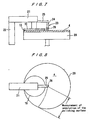
- the dressing apparatus for obtaining a desired surface of the polishing cloth by utilizing the above principles will be described below with reference to FIGS. 7 and 8.
- the dresser 10 having the annular diamond grain layer 13 is supported by a dresser head 21 which is supported by a rotating shaft 22.
- a measuring device 23 for measuring a surface contour of the polishing cloth 4 is fixed to the dresser head 21.
- the measuring device 23 comprises a measuring unit 24 comprising a micrometer, a support unit 25 for supporting the measuring unit 24, and a contact 26 comprising a roller which is fixed to the forward end of the measuring unit 24.
- the rotation of the turntable 20 is stopped, the contact 26 contacts the surface of the polishing cloth 4, and the dresser head 21 is swung about the rotating shaft 22 by rotating the rotating shaft 22 about its own axis.
- the contact 26 is moved radially while it contacts the surface of the polishing cloth 4, and the heights at radial positions of the polishing cloth in a radial direction thereof are measured during movement of the contact 26. That is, the surface contour, i.e., the undulation of the surface of the polishing cloth 4 in a radial direction thereof is measured.
- the contact type of sensor is desirable to measure the surface contour rather than the noncontact type of sensor when measuring the undulation of the surface of the polishing cloth.
- step 1 the heights at radial positions of the polishing cloth in a radial direction thereof are measured, and the obtained values which are set to initial values are memorized.
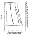
- FIG. 10 shows the heights of the surface of the polishing cloth at radial positions of the polishing cloth in a radial direction thereof.
- the horizontal axis represents a radius (mm) of the polishing cloth
- the vertical axis represents the heights which are actually measured.
- the curve A shows initial values which are the heights at radial positions of the polishing cloth in a radial direction thereof.
- step 2 the rotational speed of the turntable 20 and the rotational speed of the dresser 10 are set.
- step 3 the semiconductor wafer 2 is polished by the use of the polishing cloth 4 while supplying the abrasive liquid from the abrasive liquid supply nozzle 5 (see FIG. 1).
- step 4 the dressing of the polishing cloth 4 is performed by the dresser 10.
- step 5 the heights at radial positions of the polishing cloth in a radial direction thereof are measured by the measuring device 23.
- the curve B shows the heights at radial positions of the polishing cloth in a radial direction thereof when the rotational speed ratio of the turntable to the dresser is 1:0.5.
- the curve C shows the heights at radial positions of the polishing cloth in a radial direction thereof when the rotational speed ratio of the turntable to the dresser is 1:0.7.
- step 6 the measured values obtained in step 5 is subtracted from the initial values obtained in step 1 to obtain the removal thickness of material from the polishing cloth at radial positions of the polishing cloth in a radial direction thereof.
- FIG. 11 shows the removal thickness of material from the polishing cloth at radial positions of the polishing cloth in a radial direction thereof.
- the horizontal axis represents the radius (mm) of the polishing cloth
- the vertical axis represents the removal thickness of material from the polishing cloth.
- the curve D shows the removal thickness of material at radial positions of the polishing cloth in a radial direction thereof when the rotational speed ratio of the turntable to the dresser is 1:0.5.
- the curve E shows the removal thickness of material at radial positions of the polishing cloth in a radial direction thereof when the rotational speed ratio of the turntable to the dresser is 1:0.7.
- step 7 the obtained curve such as the curve D or E is compared with the preset desired surface of the polishing cloth. If the removal thickness of material from the polishing cloth is greater at the inner circumferential region than at the outer circumferential region, the rotational speed of the dresser 10 is lowered in step 8. If the removal thickness of material from the polishing cloth is in an allowable range at the inner and outer circumferential regions, the rotational speed of the dresser 10 is not changed in step 9. If the removal thickness of material from the polishing cloth is greater at the outer circumferential region than at the inner circumferential region, the rotational speed of the dresser 10 is increased in step 10. In steps 8 through 10, the rotational speed of the turntable is not changed. After setting the rotational speed of the dresser 10 to an optimum value in steps 8 through 10, a next dressing process is performed by the set value of the rotational speed of the dresser 10.
- the heights of a surface of the polishing cloth at radial positions of the polishing cloth are measured.
- the heights of the surface of the polishing cloth are directly related to the thickness of the polishing cloth. That is, irregularities of the removal thickness of material from the polishing cloth cause irregularities of the thickness of the polishing cloth, resulting in irregularities of the heights of the surface of the polishing cloth.
- To correct the heights of the surface of the polishing cloth corresponds to correction of the thicknesses of the surface of the polishing cloth.
- the contact type of the sensor is used to measure the heights of the polishing cloth, and the surface contour of the polishing cloth is controlled on the basis of the measured values. It is also possible to control the surface contour of the polishing cloth by measuring the thicknesses of the polishing cloth with a thickness detector and utilizing the measured values.
- the surface contour of the polishing cloth is controlled so as to be flat by the dressing process.
- the surface of the turntable may be slightly convex, and thus the surface of the polishing cloth mounted on the turntable may be slightly convex in accordance with the purpose or condition of the polishing process.
- the surface contour of the polishing cloth may be controlled so as to be slightly convex by adjusting a rotational speed ratio of the turntable to the dresser according to the present invention.
- the annular diamond grain layer and the annular SiC layer have a circular outer shape and a circular inner shape, respectively, they may have an elliptical outer shape and a elliptical inner shape, respectively, or a circular outer shape and a heart-shaped inner shape, or any other shapes.
- the dresser may have a solid circular diamond layer or a solid circular SiC layer without having a hollow portion.
- the dresser may also comprise a dresser body, and a plurality of small circular contacting portions made of diamond grains and arranged in a circular array on the dresser body.
- the rotational speed of the dresser relative to the rotational speed of the turntable is determined on the basis of the measured values, and a dressing process is performed in the determined rotational speed ratio of the turntable to the dresser, the polishing cloth is uniformly dressed in a radial direction to have a desired surface contour from the inner circumferential region to the outer circumferential region thereof.
- the polishing cloth is dressed in such a manner that the rotational speed of the dresser is lower than the rotational speed of the turntable.
- the rotational speed ratio of the turntable to the dresser is in the range of 1:0.4 to 1:0.85.
- the removal thickness of material from the polishing cloth is substantially uniform from the inner region to the outer region of the polishing cloth. Therefore, a workpiece such as a semiconductor wafer having a device pattern thereon can be polished to a flat mirror finish by the use of the thus dressed polishing cloth.
Landscapes
- Engineering & Computer Science (AREA)
- Mechanical Engineering (AREA)
- Finish Polishing, Edge Sharpening, And Grinding By Specific Grinding Devices (AREA)
- Grinding-Machine Dressing And Accessory Apparatuses (AREA)
- Mechanical Treatment Of Semiconductor (AREA)
Claims (8)
- Eine Poliervorrichtung zum Polieren einer Oberfläche eines Werkstücks, die Folgendes aufweist:wobei eine Drehgeschwindigkeit der Aufbereitungseinrichtung bezüglich einer Drehgeschwindigkeit des Drehtischs auf der Basis der gemessenen Höhen bestimmt wird und wobei das Poliertuch aufbereitet wird durch Drücken der Aufbereitungseinrichtung gegen das Poliertuch während sich der Drehtisch und die Aufbereitungseinrichtung drehen.einen Drehtisch (20) mit einem Poliertuch;Mittel zum Drehen des Drehtischs;einen oberen Ring bzw. Topring (3) zum Tragen des zu polierenden Werkstücks und zum Drücken des Werkstücks gegen das Poliertuch;eine Abricht- bzw. Aufbereitungseinrichtung bzw. einen Dresser (10) zum Aufbereiten bzw. Abrichten des Poliertuchs auf dem Drehtisch;einen Betätiger (15) zum Drehen der Aufbereitungseinrichtung um eine Mittelachse der Aufbereitungseinrichtung und zwar in derselben Richtung wie der Drehtisch; undeine Messeinrichtung (23) zum Messen der Höhen einer Oberfläche des Poliertuchs an Radialpositionen des Poliertuchs in einer Radialrichtung davon;
- Poliervorrichtung nach Anspruch 1, wobei die Messeinrichtung (23) einen Sensor aufweist zum Messen von Höhen der Polieroberfläche in einer Radialrichtung der Polieroberfläche.
- Poliervorrichtung nach Anspruch 2, wobei der Sensor einen Sensor des Kontakttyps aufweist, der die Polieroberfläche kontaktiert.
- Poliervorrichtung zum Polieren einer Oberfläche eines Werkstücks unter Verwendung einer Poliervorrichtung gemäß Anspruch 1, wobei das Verfahren Folgendes aufweist:Polieren einer Oberfläche eines Werkstücks durch Tragen des Werkstücks und Drücken desselben gegen eine Polieroberfläche auf einem Drehtisch (20);Messen von Höhen der Polieroberfläche durch eine Messeinrichtung (23); undBestimmen einer Drehgeschwindigkeit einer Abricht- bzw. Aufbereitungseinrichtung (10) und des Drehtischs (20) durch Vergleichen der gemessenen Höhen der Polieroberfläche mit der voreingestellten gewünschten Oberfläche; undAbrichten bzw. Aufbereiten der Polieroberfläche durch Drücken der Aufbereitungseinrichtung (10) gegen die Polieroberfläche.
- Polierverfahren nach Anspruch 4, das ferner das Einstellen eines Aufbereitungszustands der Aufbereitungseinrichtung auf der Basis der gemessenen Höhen aufweist.
- Polierverfahren nach Anspruch 5, wobei der Aufbereitungszustand der Aufbereitungseinrichtung (10) die Drehgeschwindigkeit der Aufbereitungseinrichtung (10) aufweist.
- Polierverfahren nach Anspruch 4, wobei die Messeinrichtung einen Sensor zum Messen von Höhen der Polieroberfläche aufweist.
- Polierverfahren nach Anspruch 7, wobei der Sensor einen Sensor des Kontakttyps aufweist, der die Polieroberfläche kontaktiert.
Priority Applications (1)
| Application Number | Priority Date | Filing Date | Title |
|---|---|---|---|
| EP04007817A EP1439031A1 (de) | 1996-06-25 | 1997-06-25 | Verfahren und Vorrichtung zum Abrichten eines Poliertuches |
Applications Claiming Priority (3)
| Application Number | Priority Date | Filing Date | Title |
|---|---|---|---|
| JP18401296 | 1996-06-25 | ||
| JP18401296 | 1996-06-25 | ||
| EP97110400A EP0816017B1 (de) | 1996-06-25 | 1997-06-25 | Verfahren und Vorrichtung zum Abrichten eines Poliertuches |
Related Parent Applications (1)
| Application Number | Title | Priority Date | Filing Date |
|---|---|---|---|
| EP97110400A Division EP0816017B1 (de) | 1996-06-25 | 1997-06-25 | Verfahren und Vorrichtung zum Abrichten eines Poliertuches |
Related Child Applications (1)
| Application Number | Title | Priority Date | Filing Date |
|---|---|---|---|
| EP04007817A Division EP1439031A1 (de) | 1996-06-25 | 1997-06-25 | Verfahren und Vorrichtung zum Abrichten eines Poliertuches |
Publications (3)
| Publication Number | Publication Date |
|---|---|
| EP1053828A2 EP1053828A2 (de) | 2000-11-22 |
| EP1053828A3 EP1053828A3 (de) | 2001-12-19 |
| EP1053828B1 true EP1053828B1 (de) | 2004-06-16 |
Family
ID=16145796
Family Applications (3)
| Application Number | Title | Priority Date | Filing Date |
|---|---|---|---|
| EP04007817A Withdrawn EP1439031A1 (de) | 1996-06-25 | 1997-06-25 | Verfahren und Vorrichtung zum Abrichten eines Poliertuches |
| EP00113403A Expired - Lifetime EP1053828B1 (de) | 1996-06-25 | 1997-06-25 | Verfahren und Vorrichtung zum Abrichten eines Poliertuches |
| EP97110400A Expired - Lifetime EP0816017B1 (de) | 1996-06-25 | 1997-06-25 | Verfahren und Vorrichtung zum Abrichten eines Poliertuches |
Family Applications Before (1)
| Application Number | Title | Priority Date | Filing Date |
|---|---|---|---|
| EP04007817A Withdrawn EP1439031A1 (de) | 1996-06-25 | 1997-06-25 | Verfahren und Vorrichtung zum Abrichten eines Poliertuches |
Family Applications After (1)
| Application Number | Title | Priority Date | Filing Date |
|---|---|---|---|
| EP97110400A Expired - Lifetime EP0816017B1 (de) | 1996-06-25 | 1997-06-25 | Verfahren und Vorrichtung zum Abrichten eines Poliertuches |
Country Status (4)
| Country | Link |
|---|---|
| US (2) | US6364752B1 (de) |
| EP (3) | EP1439031A1 (de) |
| KR (1) | KR100524510B1 (de) |
| DE (2) | DE69729590T2 (de) |
Families Citing this family (25)
| Publication number | Priority date | Publication date | Assignee | Title |
|---|---|---|---|---|
| TW375556B (en) * | 1997-07-02 | 1999-12-01 | Matsushita Electric Industrial Co Ltd | Method of polishing the wafer and finishing the polishing pad |
| US5951370A (en) * | 1997-10-02 | 1999-09-14 | Speedfam-Ipec Corp. | Method and apparatus for monitoring and controlling the flatness of a polishing pad |
| JP3615931B2 (ja) | 1998-03-26 | 2005-02-02 | 株式会社荏原製作所 | ポリッシング装置および該ポリッシング装置におけるコンディショニング方法 |
| EP1075898A3 (de) * | 1999-08-13 | 2003-11-05 | Mitsubishi Materials Corporation | Abrichtwerkzeug und Vorrichtung |
| JP2001129755A (ja) * | 1999-08-20 | 2001-05-15 | Ebara Corp | 研磨装置及びドレッシング方法 |
| JP2001212750A (ja) * | 1999-11-25 | 2001-08-07 | Fujikoshi Mach Corp | ポリシングマシンの洗浄装置およびポリシングマシン |
| US6969305B2 (en) | 2000-02-07 | 2005-11-29 | Ebara Corporation | Polishing apparatus |
| JP3862911B2 (ja) | 2000-02-07 | 2006-12-27 | 株式会社荏原製作所 | 研磨装置 |
| TW495416B (en) | 2000-10-24 | 2002-07-21 | Ebara Corp | Polishing apparatus |
| JP3768399B2 (ja) * | 2000-11-17 | 2006-04-19 | 株式会社荏原製作所 | ドレッシング装置及びポリッシング装置 |
| KR20020067789A (ko) * | 2001-02-19 | 2002-08-24 | 삼성전자 주식회사 | 다이아몬드 디스크 드레싱 설비 |
| KR100462868B1 (ko) * | 2001-06-29 | 2004-12-17 | 삼성전자주식회사 | 반도체 폴리싱 장치의 패드 컨디셔너 |
| US20070212983A1 (en) * | 2006-03-13 | 2007-09-13 | Applied Materials, Inc. | Apparatus and methods for conditioning a polishing pad |
| CN100500377C (zh) * | 2006-04-03 | 2009-06-17 | 深圳南玻显示器件科技有限公司 | 透明导电膜层抛光装置及其抛光方法 |
| KR100831019B1 (ko) | 2006-12-28 | 2008-05-20 | 주식회사 실트론 | 웨이퍼 연삭휠 및 이 연삭휠을 이용한 웨이퍼 연삭방법 |
| JP5415735B2 (ja) * | 2008-09-26 | 2014-02-12 | 株式会社荏原製作所 | ドレッシング方法、ドレッシング条件の決定方法、ドレッシング条件決定プログラム、および研磨装置 |
| JP5504901B2 (ja) | 2010-01-13 | 2014-05-28 | 株式会社Sumco | 研磨パッドの形状修正方法 |
| JP5896625B2 (ja) * | 2011-06-02 | 2016-03-30 | 株式会社荏原製作所 | 研磨装置に使用される研磨パッドの研磨面を監視する方法および装置 |
| US20130196572A1 (en) * | 2012-01-27 | 2013-08-01 | Sen-Hou Ko | Conditioning a pad in a cleaning module |
| JP5964262B2 (ja) * | 2013-02-25 | 2016-08-03 | 株式会社荏原製作所 | 研磨装置に使用される研磨部材のプロファイル調整方法、および研磨装置 |
| JP6474209B2 (ja) * | 2014-07-23 | 2019-02-27 | ファナック株式会社 | スポット溶接ガンの電極の研磨システム |
| DE102015220090B4 (de) | 2015-01-14 | 2021-02-18 | Siltronic Ag | Verfahren zum Abrichten von Poliertüchern |
| DE102016211709B3 (de) * | 2016-06-29 | 2017-11-02 | Siltronic Ag | Vorrichtung und Verfahren zum Abrichten von Poliertüchern |
| DE102016222144A1 (de) | 2016-11-11 | 2018-05-17 | Siltronic Ag | Vorrichtung und Verfahren zum Abrichten von Poliertüchern |
| CN115673978A (zh) * | 2021-07-30 | 2023-02-03 | 上海超硅半导体股份有限公司 | 一种抛光布整理辅助装置及使用方法 |
Family Cites Families (18)
| Publication number | Priority date | Publication date | Assignee | Title |
|---|---|---|---|---|
| US3031806A (en) * | 1960-04-12 | 1962-05-01 | Crane Packing Co | Automatic lap plate contour control |
| JPH0775825B2 (ja) | 1986-01-07 | 1995-08-16 | 東芝機械株式会社 | 片面研磨装置 |
| US4984390A (en) * | 1989-11-09 | 1991-01-15 | Nippei Toyama Corporation | Grinding disc dressing apparatus |
| US5384986A (en) * | 1992-09-24 | 1995-01-31 | Ebara Corporation | Polishing apparatus |
| US5456627A (en) * | 1993-12-20 | 1995-10-10 | Westech Systems, Inc. | Conditioner for a polishing pad and method therefor |
| US5486131A (en) * | 1994-01-04 | 1996-01-23 | Speedfam Corporation | Device for conditioning polishing pads |
| JP2914166B2 (ja) * | 1994-03-16 | 1999-06-28 | 日本電気株式会社 | 研磨布の表面処理方法および研磨装置 |
| US5698455A (en) * | 1995-02-09 | 1997-12-16 | Micron Technologies, Inc. | Method for predicting process characteristics of polyurethane pads |
| US5708506A (en) * | 1995-07-03 | 1998-01-13 | Applied Materials, Inc. | Apparatus and method for detecting surface roughness in a chemical polishing pad conditioning process |
| US5609718A (en) * | 1995-09-29 | 1997-03-11 | Micron Technology, Inc. | Method and apparatus for measuring a change in the thickness of polishing pads used in chemical-mechanical planarization of semiconductor wafers |
| US5875559A (en) | 1995-10-27 | 1999-03-02 | Applied Materials, Inc. | Apparatus for measuring the profile of a polishing pad in a chemical mechanical polishing system |
| US5743784A (en) * | 1995-12-19 | 1998-04-28 | Applied Materials, Inc. | Apparatus and method to determine the coefficient of friction of a chemical mechanical polishing pad during a pad conditioning process and to use it to control the process |
| US5618447A (en) | 1996-02-13 | 1997-04-08 | Micron Technology, Inc. | Polishing pad counter meter and method for real-time control of the polishing rate in chemical-mechanical polishing of semiconductor wafers |
| TW355153B (en) * | 1996-05-21 | 1999-04-01 | Toshiba Machine Co Ltd | A method for leveling abrasive cloth and device for the same |
| US5954570A (en) | 1996-05-31 | 1999-09-21 | Kabushiki Kaisha Toshiba | Conditioner for a polishing tool |
| US5975994A (en) * | 1997-06-11 | 1999-11-02 | Micron Technology, Inc. | Method and apparatus for selectively conditioning a polished pad used in planarizng substrates |
| US6045434A (en) * | 1997-11-10 | 2000-04-04 | International Business Machines Corporation | Method and apparatus of monitoring polishing pad wear during processing |
| US6343974B1 (en) * | 2000-06-26 | 2002-02-05 | International Business Machines Corporation | Real-time method for profiling and conditioning chemical-mechanical polishing pads |
-
1997
- 1997-06-24 KR KR1019970026641A patent/KR100524510B1/ko not_active Expired - Fee Related
- 1997-06-25 EP EP04007817A patent/EP1439031A1/de not_active Withdrawn
- 1997-06-25 DE DE69729590T patent/DE69729590T2/de not_active Expired - Fee Related
- 1997-06-25 EP EP00113403A patent/EP1053828B1/de not_active Expired - Lifetime
- 1997-06-25 US US08/881,616 patent/US6364752B1/en not_active Expired - Fee Related
- 1997-06-25 EP EP97110400A patent/EP0816017B1/de not_active Expired - Lifetime
- 1997-06-25 DE DE69715321T patent/DE69715321T2/de not_active Expired - Fee Related
-
2002
- 2002-02-01 US US10/060,366 patent/US6905400B2/en not_active Expired - Lifetime
Also Published As
| Publication number | Publication date |
|---|---|
| EP1439031A1 (de) | 2004-07-21 |
| EP1053828A3 (de) | 2001-12-19 |
| KR980005776A (ko) | 1998-03-30 |
| US6905400B2 (en) | 2005-06-14 |
| EP0816017B1 (de) | 2002-09-11 |
| DE69729590D1 (de) | 2004-07-22 |
| US6364752B1 (en) | 2002-04-02 |
| KR100524510B1 (ko) | 2006-01-12 |
| US20020072300A1 (en) | 2002-06-13 |
| DE69715321D1 (de) | 2002-10-17 |
| DE69715321T2 (de) | 2003-07-31 |
| EP0816017A1 (de) | 1998-01-07 |
| DE69729590T2 (de) | 2005-06-09 |
| EP1053828A2 (de) | 2000-11-22 |
Similar Documents
| Publication | Publication Date | Title |
|---|---|---|
| EP0816017B1 (de) | Verfahren und Vorrichtung zum Abrichten eines Poliertuches | |
| US11577361B2 (en) | Retaining ring with shaped surface and method of forming | |
| US6354918B1 (en) | Apparatus and method for polishing workpiece | |
| US6238271B1 (en) | Methods and apparatus for improved polishing of workpieces | |
| US12285838B2 (en) | Wafer edge asymmetry correction using groove in polishing pad | |
| US6685548B2 (en) | Grooved polishing pads and methods of use | |
| US5329734A (en) | Polishing pads used to chemical-mechanical polish a semiconductor substrate | |
| KR100525652B1 (ko) | 폴리싱 장치 | |
| KR20030066796A (ko) | 표면적을 감소시킨 폴리싱 패드와 가변적/부분적패드-웨이퍼 중복 기술을 이용한 반도체 웨이퍼의 폴리싱및 평탄화 시스템 및 방법 | |
| EP1063056A2 (de) | Verfahren und Vorrichtung zum Messen eines Polierkissenprofils und Steuerung mit geschlossenem Regelkreis eines Polierkissen Aufbereitungsverfahren | |
| US6302770B1 (en) | In-situ pad conditioning for CMP polisher | |
| US6271140B1 (en) | Coaxial dressing for chemical mechanical polishing | |
| US5985090A (en) | Polishing cloth and polishing apparatus having such polishing cloth | |
| JP2003151934A (ja) | Cmp装置及びcmp用研磨パッドの調整方法 | |
| US6652366B2 (en) | Dynamic slurry distribution control for CMP | |
| KR20050115526A (ko) | 연마 패드 어셈블리, 이를 갖는 웨이퍼 연마 장치 그리고이들을 이용한 웨이퍼 연마 방법 | |
| JP3640504B2 (ja) | ドレッシング方法及び装置 | |
| EP1157783B1 (de) | Polierverfahren und Vorrichtung | |
| EP0769350A1 (de) | Verfahren und Vorrichtung zum Abrichten von Poliertuch | |
| WO2001058644A1 (en) | Method and apparatus for controlling a pad conditioning process of a chemical-mechanical polishing apparatus | |
| US6776870B2 (en) | Ditch type floating ring for chemical mechanical polishing | |
| KR100886603B1 (ko) | 웨이퍼 연마 장치 및 웨이퍼 연마 방법 | |
| KR20000018859U (ko) | 반도체 웨이퍼 연마장치 |
Legal Events
| Date | Code | Title | Description |
|---|---|---|---|
| PUAI | Public reference made under article 153(3) epc to a published international application that has entered the european phase |
Free format text: ORIGINAL CODE: 0009012 |
|
| AC | Divisional application: reference to earlier application |
Ref document number: 816017 Country of ref document: EP |
|
| AK | Designated contracting states |
Kind code of ref document: A2 Designated state(s): DE FR |
|
| PUAL | Search report despatched |
Free format text: ORIGINAL CODE: 0009013 |
|
| AK | Designated contracting states |
Kind code of ref document: A3 Designated state(s): DE FR |
|
| 17P | Request for examination filed |
Effective date: 20020619 |
|
| AKX | Designation fees paid |
Free format text: DE FR |
|
| 17Q | First examination report despatched |
Effective date: 20020927 |
|
| GRAP | Despatch of communication of intention to grant a patent |
Free format text: ORIGINAL CODE: EPIDOSNIGR1 |
|
| RIN1 | Information on inventor provided before grant (corrected) |
Inventor name: ISHII, YOU Inventor name: SAKURAI TAKESHI Inventor name: NISHI, TOYOMI Inventor name: KIMURA, NORIO Inventor name: KAWAMOTO, TAKAYOSHI |
|
| RIN1 | Information on inventor provided before grant (corrected) |
Inventor name: SAKURAI TAKESHI Inventor name: KAWAMOTO, TAKAYOSHI Inventor name: NISHI, TOYOMI Inventor name: KIMURA, NORIO Inventor name: ISHII, YOU |
|
| GRAS | Grant fee paid |
Free format text: ORIGINAL CODE: EPIDOSNIGR3 |
|
| GRAA | (expected) grant |
Free format text: ORIGINAL CODE: 0009210 |
|
| RIN1 | Information on inventor provided before grant (corrected) |
Inventor name: ISHII, YOU Inventor name: SAKURAI TAKESHIC/O EBARA CORP. Inventor name: KAWAMOTO, TAKAYOSHI Inventor name: NISHI, TOYOMI Inventor name: KIMURA, NORIO |
|
| AC | Divisional application: reference to earlier application |
Ref document number: 0816017 Country of ref document: EP Kind code of ref document: P |
|
| AK | Designated contracting states |
Kind code of ref document: B1 Designated state(s): DE FR |
|
| RIN1 | Information on inventor provided before grant (corrected) |
Inventor name: ISHII, YOU Inventor name: KIMURA, NORIO Inventor name: SAKURAI, TAKESHIC/O EBARA CORP. Inventor name: KAWAMOTO, TAKAYOSHI Inventor name: NISHI, TOYOMI |
|
| REF | Corresponds to: |
Ref document number: 69729590 Country of ref document: DE Date of ref document: 20040722 Kind code of ref document: P |
|
| RIN2 | Information on inventor provided after grant (corrected) |
Inventor name: SAKURAI, TAKESHI Inventor name: ISHII, YOU Inventor name: KAWAMOTO, TAKAYOSHI Inventor name: NISHI, TOYOMI Inventor name: KIMURA, NORIO |
|
| ET | Fr: translation filed | ||
| PLBE | No opposition filed within time limit |
Free format text: ORIGINAL CODE: 0009261 |
|
| STAA | Information on the status of an ep patent application or granted ep patent |
Free format text: STATUS: NO OPPOSITION FILED WITHIN TIME LIMIT |
|
| 26N | No opposition filed |
Effective date: 20050317 |
|
| PGFP | Annual fee paid to national office [announced via postgrant information from national office to epo] |
Ref country code: FR Payment date: 20080617 Year of fee payment: 12 |
|
| PGFP | Annual fee paid to national office [announced via postgrant information from national office to epo] |
Ref country code: DE Payment date: 20090619 Year of fee payment: 13 |
|
| REG | Reference to a national code |
Ref country code: FR Ref legal event code: ST Effective date: 20100226 |
|
| PG25 | Lapsed in a contracting state [announced via postgrant information from national office to epo] |
Ref country code: FR Free format text: LAPSE BECAUSE OF NON-PAYMENT OF DUE FEES Effective date: 20090630 |
|
| PG25 | Lapsed in a contracting state [announced via postgrant information from national office to epo] |
Ref country code: DE Free format text: LAPSE BECAUSE OF NON-PAYMENT OF DUE FEES Effective date: 20110101 |