EP1053836B1 - Bras de soutien pour l'alimentation en énergie - Google Patents
Bras de soutien pour l'alimentation en énergie Download PDFInfo
- Publication number
- EP1053836B1 EP1053836B1 EP00109756A EP00109756A EP1053836B1 EP 1053836 B1 EP1053836 B1 EP 1053836B1 EP 00109756 A EP00109756 A EP 00109756A EP 00109756 A EP00109756 A EP 00109756A EP 1053836 B1 EP1053836 B1 EP 1053836B1
- Authority
- EP
- European Patent Office
- Prior art keywords
- robot
- base part
- cables
- robot according
- leg
- Prior art date
- Legal status (The legal status is an assumption and is not a legal conclusion. Google has not performed a legal analysis and makes no representation as to the accuracy of the status listed.)
- Expired - Lifetime
Links
Images

Classifications
-
- B—PERFORMING OPERATIONS; TRANSPORTING
- B25—HAND TOOLS; PORTABLE POWER-DRIVEN TOOLS; MANIPULATORS
- B25J—MANIPULATORS; CHAMBERS PROVIDED WITH MANIPULATION DEVICES
- B25J19/00—Accessories fitted to manipulators, e.g. for monitoring, for viewing; Safety devices combined with or specially adapted for use in connection with manipulators
- B25J19/0025—Means for supplying energy to the end effector
-
- Y—GENERAL TAGGING OF NEW TECHNOLOGICAL DEVELOPMENTS; GENERAL TAGGING OF CROSS-SECTIONAL TECHNOLOGIES SPANNING OVER SEVERAL SECTIONS OF THE IPC; TECHNICAL SUBJECTS COVERED BY FORMER USPC CROSS-REFERENCE ART COLLECTIONS [XRACs] AND DIGESTS
- Y10—TECHNICAL SUBJECTS COVERED BY FORMER USPC
- Y10T—TECHNICAL SUBJECTS COVERED BY FORMER US CLASSIFICATION
- Y10T74/00—Machine element or mechanism
- Y10T74/20—Control lever and linkage systems
- Y10T74/20207—Multiple controlling elements for single controlled element
- Y10T74/20305—Robotic arm
- Y10T74/20311—Robotic arm including power cable or connector
Definitions
- the invention relates to a robot with cables extending at least partly on the outside.
- Such cables are supplied in a hose supply cables of tools of the robot, with a reserve of length, in particular in the region of the axis A3 of the robot.
- the resulting distance changes between individual points of the robot are particularly important in the management of supply cables, such as tools of the robot to pay attention.
- the supply cables In order to make such distance changes without stressing the supply cable, the supply cables must have a reserve of length. In the case of supply cables routed on the outside, there is the problem that in working positions of the robot arm, in which the length reserve is not used, the supply cables can cause a relatively large interference contour and that the supply cable can be broken by stress due to the length reserve.
- the DE 92 17 659 U shows a robot in which on the top of the arm of the robot, a block is arranged with two vertically upstanding rods, which extend substantially horizontally, at a finite relative angle to each other flexible arms, which are thus bendable in all directions, to whose ends are arranged annular elements through which a supply line is guided.
- the invention is therefore the object of developing a generic robot to the effect that with the simplest possible components, which is kept as low as possible by the supply cable interference contour and that under sufficiently precise guidance of the cable despite their length reserve, a kinking the same is avoided.
- the object is achieved in a robot of the type mentioned by the features of the characterizing part of claim 1.
- the supply cables Due to the base part carrying the supply cables in the region of their length reserve, the supply cables furthermore have a tight guide on the outside of the robot parts, which leads to a reduced interference contour and due to the increased guidance also leads to a smaller risk of bending the supply cables.
- the arrangement of the supply cable to the base part and the lateral deflection of the supply cable is greatly reduced.
- the cable guide tracked the claimed cable, which is significantly reduced by the angle between the guide elements of the Abknickrisiko.
- the base part stops, which limited the pivotability of the leg in both Verschwenkungslegien and with which it can be ensured that the routing of the supply cable can vary only in a certain limited area.
- the thigh or arm is basically freely movable in the limited area. Its position is determined by the tube held by it and its elasticity.
- the leg may additionally be connected by a spring element with the base part, which holds the leg in the unloaded state in a certain position and from which it can be moved out only by a force acting against the spring force stress.
- a bar for fixing the individual supply cable is arranged on the base part, whereby they are fixed in the initial region of the length reserve and thus there is no effect on the cable management in the section before the length reserve.
- this bar on individual holes in which the supply cable can be individually guided and thus also fixed individually, whereby interference of the supply cables to each other are largely avoided.
- the supply cables are movably guided on the guide element on the leg.
- the supply cables remain movable along the path given by the guide elements and can follow the movements of the robot arm.
- the supply cables are guided in a protective tube, which prevents damage or even a twisting of the supply cable, wherein the hose is fixed to the base part itself and is movably guided on the leg.
- the base part has further means for attaching guide elements for the supply cable, with which occurring overlengths can be performed optimally, ie with minimal interference contour on the robot parts.
- the base part has a fastening element for connection to a robot arm of the robot, which is arranged in particular advantageously on the motor screws of the axis A3.
- the arrangement of the Befest Trentselments in the immediate region of the axis of rotation of the robot arm results in movements of the robot arm to a relative movement between the supply cable and the base part, wherein the stationary in relation to the rotational movements of the robot arm about the axis A3 of the robot base ensures the kink-free guidance of the supply cable.
- the fastener is a bottle.
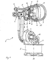
- inventive robots 1 has a base 2 with a seated on this, about the vertical axis A1 pivotable carousel 3.
- a first robot arm 4 is arranged pivotably about the axis A2 on the carousel 3.
- a second robot arm 5, which carries the robot hand 6 for receiving machining tools, etc., is arranged pivotably on the robot arm 4 about the horizontal axis A3.
- cables are routed to a cable separation point 7 arranged on the robot arm 5. From the cable separation point 7 lead supply cable 8 to the arranged on the robot hand 6, not shown tool.
- the supply cable 7 are guided in a protective tube 9, wherein the protective tube 9 and thus the supply cable 7 in a first downwardly directed, largely circular loop, which is then guided largely parallel to the robot arm 5 to the robot hand 6.
- the protective tube 9 is fixed at its beginning by a cable clamp 10 on the robot arm 5 and at its end by a clamp 11 on the robot hand 6. Between the two fixed clamps 10 and 11 of the protective tube 9 is guided floating on clamps 12,13 and 14.
- the clamps 10 and 12 are arranged in the region of the robot axis A3 together on a base part 15 in the form of a base plate.
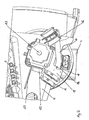
- Fig. 2 shows a section of the robot 1 from Fig. 1 in the region of the axis A3, around which the robot arm 5 is pivotably arranged on the robot arm 4.
- Fig. 2 are only the connections of the cable separation point 7 but not in Fig. 1 shown supply cable 8 and the protective tube 9 shown.
- the base part 15 is arranged, which has corresponding bores 16 in order to be fixed to the robot arm 5 together with the motor.
- the area of the axis A3 is also a arranged against the base part of movable legs 17.
- the leg 17 is pivotally mounted on the base part 15, wherein the pivotability is limited by a guided in a recess with stops of the base part 15 pin 18 of the leg 17.
- the leg 17 is held on the base part 15 by a tension spring 20 in a preferred position, largely relaxed, need not be provided, from which the leg 17 can be pivoted with the clamp 12 only against the force of the spring 20 about the axis 21 .
- the spring 20 arranged between the base part 15 and the leg 17 pulls the leg 17 into the position in which the pin 18 of the leg engages with the stop 19b (FIG. Fig. 2 ) the base part 15 comes into contact.
- the leg 17 can be pivoted against the tensile force of the spring 20, so that the guide clamp 12 is tracked with the leg 17 of the movement of the cable to avoid kinking of the cable.
- the base member 15 a by means of a plate 22 of the base plate 19 remote bar 23 with holes 24 for receiving and guiding the supply cable in the area between the cable separation point 7 and the beginning of the protective tube 9 in the region of the cable clamp 10.
Landscapes
- Engineering & Computer Science (AREA)
- Robotics (AREA)
- Mechanical Engineering (AREA)
- Manipulator (AREA)
- Electrical Discharge Machining, Electrochemical Machining, And Combined Machining (AREA)
Claims (11)
- Robot comprenant des câbles disposés au moins partiellement du côté extérieur avec une réserve de longueur et comprenant une embase (15) disposée sur le robot (1) dans la zone de la réserve de longueur, avec des éléments de guidage des câbles, caractérisé par un premier élément (10) fixé sur l'embase pour le guidage des câbles (8) et un bras (17) disposé sur l'embase (15) pouvant pivoter à l'encontre de celle-ci, sur lequel est monté un autre élément (12) pour le guidage flottant des câbles (8).
- Robot selon la revendication 1, caractérisé en ce que l'embase (15) présente des butées pour délimiter le pivotement du bras (17).
- Robot selon la revendication 1 ou 2, caractérisé en ce qu'un élément élastique (20) est disposé entre le bras (17) et l'embase (15).
- Robot selon l'une quelconque des revendications 1 à 3, caractérisé en ce que l'embase (15) présente une règle (23) pour la fixation individuelle des câbles (8).
- Robot selon la revendication 4, caractérisé en ce que la règle (23) présente des perçages (24) individuels.
- robot selon l'une quelconque des revendications 1 à 5, caractérisé en ce que les câbles (8) sont guidés mobiles sur l'élément de guidage (12) supplémentaire sur le bras (17).
- Robot selon l'une quelconque des revendications 1 à 6, caractérisé par une gaine tubulaire de protection (9) de réception des câbles (8).
- Robot selon l'une quelconque des revendications 1 à 7, caractérisé en ce que l'embase (15) présente d'autres dispositifs de montage d'éléments de guidage.
- Robot selon l'une quelconque des revendications 1 à 8, caractérisé en ce que l'embase (15) présente un élément de fixation pour la liaison avec un bras (5) du robot.
- Robot selon la revendication 9, caractérisé en ce que l'élément de fixation est disposé sur les vis du moteur de l'axe A3 du robot.
- Robot selon l'une quelconque des revendications 9 ou 10, caractérisé en ce que l'élément de fixation est une bride.
Applications Claiming Priority (2)
| Application Number | Priority Date | Filing Date | Title |
|---|---|---|---|
| DE29908623U | 1999-05-15 | ||
| DE29908623U DE29908623U1 (de) | 1999-05-15 | 1999-05-15 | Haltearm für Energiezuführung |
Publications (3)
| Publication Number | Publication Date |
|---|---|
| EP1053836A2 EP1053836A2 (fr) | 2000-11-22 |
| EP1053836A3 EP1053836A3 (fr) | 2000-12-27 |
| EP1053836B1 true EP1053836B1 (fr) | 2008-06-25 |
Family
ID=8073594
Family Applications (1)
| Application Number | Title | Priority Date | Filing Date |
|---|---|---|---|
| EP00109756A Expired - Lifetime EP1053836B1 (fr) | 1999-05-15 | 2000-05-09 | Bras de soutien pour l'alimentation en énergie |
Country Status (3)
| Country | Link |
|---|---|
| US (1) | US6684731B1 (fr) |
| EP (1) | EP1053836B1 (fr) |
| DE (2) | DE29908623U1 (fr) |
Families Citing this family (13)
| Publication number | Priority date | Publication date | Assignee | Title |
|---|---|---|---|---|
| DE10224858B4 (de) † | 2002-06-05 | 2005-07-14 | Kuka Roboter Gmbh | Vorrichtung zum Führen eines Schlauches |
| DE29902947U1 (de) * | 1999-02-19 | 1999-07-08 | Kuka Roboter GmbH, 86165 Augsburg | Roboterteil |
| SE0002654D0 (sv) | 2000-07-14 | 2000-07-14 | Abb Ab | Manipulator |
| EP1179397A1 (fr) * | 2000-07-14 | 2002-02-13 | Abb Ab | Manipulateur équipé d'un dispositif pour soutenir les cables d'alimentation |
| JP3746244B2 (ja) * | 2002-04-10 | 2006-02-15 | ファナック株式会社 | ロボットの手首における線条体の敷設構造 |
| DE102004019838C5 (de) * | 2004-04-23 | 2013-07-25 | Kuka Roboter Gmbh | Vorrichtung zum geführten Ein- und Ausfahren von Energieleitern |
| CN101450485B (zh) * | 2007-12-06 | 2012-05-16 | 崔光述 | 工业机器人电缆导向装置 |
| JP5201186B2 (ja) | 2010-09-16 | 2013-06-05 | 株式会社安川電機 | ロボット |
| FR3001176B1 (fr) * | 2013-01-18 | 2015-02-27 | Leoni Cia Cable Systems | Dispositif de guidage et de rappel |
| DE102014209684B4 (de) * | 2014-05-21 | 2023-06-29 | Siemens Healthcare Gmbh | Medizinisches Untersuchungs- und/oder Behandlungsgerät |
| DE102015209547A1 (de) * | 2015-05-22 | 2016-11-24 | Kuka Roboter Gmbh | Roboter mit einem Energieleitungsstrang |
| DE102015210570A1 (de) * | 2015-06-09 | 2016-12-15 | Kuka Roboter Gmbh | Leitungsführungsvorrichtung eines Industrieroboters |
| WO2021201292A1 (fr) | 2020-04-03 | 2021-10-07 | Mujin, Inc. | Systèmes robotiques comprenant des mécanismes de stabilité d'acheminement |
Family Cites Families (20)
| Publication number | Priority date | Publication date | Assignee | Title |
|---|---|---|---|---|
| JPS607489B2 (ja) * | 1979-07-18 | 1985-02-25 | 旭光学工業株式会社 | レ−ザ−メス装置のカウンタ−バランス機構 |
| US4507042A (en) * | 1981-10-07 | 1985-03-26 | Yaskawa Electric Mfg. Co., Ltd. | Cable support of a robot |
| FR2528187B1 (fr) * | 1982-06-08 | 1986-01-24 | Commissariat Energie Atomique | Dispositif pour la transmission d'un faisceau energetique |
| US4625936A (en) * | 1983-06-06 | 1986-12-02 | Sine Products Company | Flexible support and carrier assembly |
| DE3434899A1 (de) * | 1983-10-19 | 1985-05-23 | Kuka Schweissanlagen + Roboter Gmbh, 8900 Augsburg | Vorrichtung zum aussenseitigen halten und fuehren von versorgungsleitungen zu bewegten werkzeugen von manipulatoren |
| US4676472A (en) * | 1985-12-09 | 1987-06-30 | Gerald Lapides | High voltage tubing conductor holding device |
| US4767257A (en) * | 1985-12-23 | 1988-08-30 | Mitsubishi Denki Kabushiki Kaisha | Industrial robot |
| JPS6339416A (ja) * | 1986-08-01 | 1988-02-19 | 松下電器産業株式会社 | 産業用ロボツトのケ−ブル支持装置 |
| JPS63185596A (ja) * | 1987-01-26 | 1988-08-01 | フアナツク株式会社 | 産業用ロボツトのケ−ブル処理装置 |
| DE3939836A1 (de) * | 1988-12-02 | 1990-06-07 | Tokico Ltd | Industrieroboter |
| JP2564388B2 (ja) * | 1989-01-30 | 1996-12-18 | ファナック株式会社 | 垂直多関節腕型産業用ロボットのオフセットアーム構造 |
| DE9217659U1 (de) * | 1992-12-24 | 1994-04-07 | Kuka Schweißanlagen + Roboter GmbH, 86165 Augsburg | Leitungsführung für eine Versorgungsleitung an einem mehrachsigen Roboter |
| US5651519A (en) * | 1995-03-14 | 1997-07-29 | Goodrich; John J. | Robot dress bar |
| US5813286A (en) * | 1996-04-04 | 1998-09-29 | Hansen; Henning | Support arm |
| US5694813A (en) * | 1996-09-23 | 1997-12-09 | Nachi Robotics Systems Inc. | Industrial robot |
| SE511235C2 (sv) * | 1996-10-14 | 1999-08-30 | Asea Brown Boveri | Anordning och förfarande för att vid en manipulator hålla och föra ett kablage |
| US5740994A (en) * | 1996-12-26 | 1998-04-21 | Erico International Corporation | Cable support and method |
| US5893490A (en) * | 1997-01-27 | 1999-04-13 | Ingersoll-Rand Company | Hose mount for robot arm dispenser system |
| CA2214549A1 (fr) * | 1997-09-02 | 1999-03-02 | Henning Hansen | Bras de support |
| US5893539A (en) * | 1997-09-25 | 1999-04-13 | Ncr Corporation | Cable management system |
-
1999
- 1999-05-15 DE DE29908623U patent/DE29908623U1/de not_active Expired - Lifetime
-
2000
- 2000-05-09 EP EP00109756A patent/EP1053836B1/fr not_active Expired - Lifetime
- 2000-05-09 DE DE50015222T patent/DE50015222D1/de not_active Expired - Lifetime
- 2000-05-12 US US09/573,716 patent/US6684731B1/en not_active Expired - Fee Related
Also Published As
| Publication number | Publication date |
|---|---|
| EP1053836A3 (fr) | 2000-12-27 |
| DE29908623U1 (de) | 1999-07-29 |
| DE50015222D1 (de) | 2008-08-07 |
| US6684731B1 (en) | 2004-02-03 |
| EP1053836A2 (fr) | 2000-11-22 |
Similar Documents
| Publication | Publication Date | Title |
|---|---|---|
| EP1053836B1 (fr) | Bras de soutien pour l'alimentation en énergie | |
| EP1964651B1 (fr) | Bras de robot pour un robot industriel | |
| EP1369211B1 (fr) | Dispositif de guidage et de rappel d'un conduit flexible de robot | |
| DE102013016734A1 (de) | Vorrichtung zur Anbindung eines Versorgungselements an einen Roboter | |
| EP0576513B1 (fr) | Manipulateur multiaxe | |
| DE102014209684B4 (de) | Medizinisches Untersuchungs- und/oder Behandlungsgerät | |
| AT509966B1 (de) | Leitungsführungseinrichtung mit einer rückstelleinheit und roboter mit einer solchen leitungsführungseinrichtung | |
| DD227376A5 (de) | Vorrichtung zum aussenseitigen halten und fuehren von versorgungsleitungen zu bewegten werkzeugen von manipulatoren | |
| DE102014109325A1 (de) | Halterungssystem für Roboter-Steuerkabel und ein Roboter damit | |
| DE102007018543B4 (de) | Vorrichtung zum Führen von Versorgungsleitungen entlang der Struktur eines Industrieroboters | |
| DE69718186T2 (de) | Kabelhalterungsvorrichtung für einen industriellen roboter | |
| DE102008056935A1 (de) | Robotersystem eines Aufhängungstyps | |
| EP0950478A2 (fr) | Robot ayant des cables situés au moins partiellement à l'extérieur du robot | |
| DE202012011535U1 (de) | Haltevorrichtung für wenigstens eine Leitung in einem Manipulatorarm und Manipulatorarm mit einer solchen Haltevorrichtung | |
| DE102012002093A1 (de) | Leitungsführungssystem zur Aufnahme und Führung von Versorgungsleitungen sowie Werkzeugmaschine | |
| EP3475038A1 (fr) | Système de manipulation | |
| DE9406405U1 (de) | Vorrichtung zum Führen einer Leitung | |
| DE3715118C2 (fr) | ||
| DE10245984A1 (de) | Vorrichtung zum Führen flexibler Elemente an Maschinen | |
| DE29803637U9 (de) | Leitungsführung für einen mehrachsigen Industrieroboter | |
| DE102006028145A1 (de) | Roboter | |
| DE602005006178T2 (de) | Roboter zum Ausführen industrieller Arbeiten mittels eines durch eine im Inneren des Roboters angeordnete optische Faser geleiteten Laserstrahls | |
| WO2010043214A1 (fr) | Dispositif et procédé permettant de guider des conduits d'alimentation le long de la structure d'un robot articulé industriel | |
| EP0979706B1 (fr) | Machine-outil | |
| DE8703229U1 (de) | Roboter |
Legal Events
| Date | Code | Title | Description |
|---|---|---|---|
| PUAI | Public reference made under article 153(3) epc to a published international application that has entered the european phase |
Free format text: ORIGINAL CODE: 0009012 |
|
| PUAL | Search report despatched |
Free format text: ORIGINAL CODE: 0009013 |
|
| AK | Designated contracting states |
Kind code of ref document: A2 Designated state(s): AT BE CH CY DE LI |
|
| AX | Request for extension of the european patent |
Free format text: AL;LT;LV;MK;RO;SI |
|
| AK | Designated contracting states |
Kind code of ref document: A3 Designated state(s): AT BE CH CY DE DK ES FI FR GB GR IE IT LI LU MC NL PT SE |
|
| AX | Request for extension of the european patent |
Free format text: AL;LT;LV;MK;RO;SI |
|
| AKX | Designation fees paid | ||
| 17P | Request for examination filed |
Effective date: 20010220 |
|
| RBV | Designated contracting states (corrected) |
Designated state(s): AT BE CH CY DE LI |
|
| RBV | Designated contracting states (corrected) |
Designated state(s): DE FR GB IT SE |
|
| 17Q | First examination report despatched |
Effective date: 20021025 |
|
| GRAP | Despatch of communication of intention to grant a patent |
Free format text: ORIGINAL CODE: EPIDOSNIGR1 |
|
| GRAS | Grant fee paid |
Free format text: ORIGINAL CODE: EPIDOSNIGR3 |
|
| GRAA | (expected) grant |
Free format text: ORIGINAL CODE: 0009210 |
|
| AK | Designated contracting states |
Kind code of ref document: B1 Designated state(s): DE FR GB IT SE |
|
| REG | Reference to a national code |
Ref country code: GB Ref legal event code: FG4D Free format text: NOT ENGLISH |
|
| RAP2 | Party data changed (patent owner data changed or rights of a patent transferred) |
Owner name: KUKA ROBOTER GMBH |
|
| REF | Corresponds to: |
Ref document number: 50015222 Country of ref document: DE Date of ref document: 20080807 Kind code of ref document: P |
|
| REG | Reference to a national code |
Ref country code: SE Ref legal event code: TRGR |
|
| PLBE | No opposition filed within time limit |
Free format text: ORIGINAL CODE: 0009261 |
|
| STAA | Information on the status of an ep patent application or granted ep patent |
Free format text: STATUS: NO OPPOSITION FILED WITHIN TIME LIMIT |
|
| 26N | No opposition filed |
Effective date: 20090326 |
|
| GBPC | Gb: european patent ceased through non-payment of renewal fee |
Effective date: 20090509 |
|
| PG25 | Lapsed in a contracting state [announced via postgrant information from national office to epo] |
Ref country code: GB Free format text: LAPSE BECAUSE OF NON-PAYMENT OF DUE FEES Effective date: 20090509 |
|
| REG | Reference to a national code |
Ref country code: DE Ref legal event code: R082 Ref document number: 50015222 Country of ref document: DE |
|
| REG | Reference to a national code |
Ref country code: FR Ref legal event code: PLFP Year of fee payment: 17 |
|
| REG | Reference to a national code |
Ref country code: FR Ref legal event code: PLFP Year of fee payment: 18 |
|
| REG | Reference to a national code |
Ref country code: FR Ref legal event code: PLFP Year of fee payment: 19 |
|
| REG | Reference to a national code |
Ref country code: DE Ref legal event code: R081 Ref document number: 50015222 Country of ref document: DE Owner name: KUKA DEUTSCHLAND GMBH, DE Free format text: FORMER OWNER: KUKA ROBOTER GMBH, 86165 AUGSBURG, DE |
|
| PGFP | Annual fee paid to national office [announced via postgrant information from national office to epo] |
Ref country code: IT Payment date: 20190527 Year of fee payment: 20 Ref country code: DE Payment date: 20190423 Year of fee payment: 20 |
|
| PGFP | Annual fee paid to national office [announced via postgrant information from national office to epo] |
Ref country code: SE Payment date: 20190513 Year of fee payment: 20 Ref country code: FR Payment date: 20190410 Year of fee payment: 20 |
|
| REG | Reference to a national code |
Ref country code: DE Ref legal event code: R071 Ref document number: 50015222 Country of ref document: DE |
|
| REG | Reference to a national code |
Ref country code: SE Ref legal event code: EUG |