EP1053901A2 - Radiateur pour moteur à combustion interne - Google Patents
Radiateur pour moteur à combustion interne Download PDFInfo
- Publication number
- EP1053901A2 EP1053901A2 EP00106381A EP00106381A EP1053901A2 EP 1053901 A2 EP1053901 A2 EP 1053901A2 EP 00106381 A EP00106381 A EP 00106381A EP 00106381 A EP00106381 A EP 00106381A EP 1053901 A2 EP1053901 A2 EP 1053901A2
- Authority
- EP
- European Patent Office
- Prior art keywords
- cooler
- section
- outer contour
- mold
- cooler according
- Prior art date
- Legal status (The legal status is an assumption and is not a legal conclusion. Google has not performed a legal analysis and makes no representation as to the accuracy of the status listed.)
- Granted
Links
Images

Classifications
-
- B—PERFORMING OPERATIONS; TRANSPORTING
- B60—VEHICLES IN GENERAL
- B60K—ARRANGEMENT OR MOUNTING OF PROPULSION UNITS OR OF TRANSMISSIONS IN VEHICLES; ARRANGEMENT OR MOUNTING OF PLURAL DIVERSE PRIME-MOVERS IN VEHICLES; AUXILIARY DRIVES FOR VEHICLES; INSTRUMENTATION OR DASHBOARDS FOR VEHICLES; ARRANGEMENTS IN CONNECTION WITH COOLING, AIR INTAKE, GAS EXHAUST OR FUEL SUPPLY OF PROPULSION UNITS IN VEHICLES
- B60K11/00—Arrangement in connection with cooling of propulsion units
- B60K11/02—Arrangement in connection with cooling of propulsion units with liquid cooling
- B60K11/04—Arrangement or mounting of radiators, radiator shutters, or radiator blinds
Definitions
- the invention relates to a cooler for internal combustion engines or units thereof according to the preamble of patent claim 1.
- a known cooler is in the Front of a motor vehicle installed and has a rectangular basic shape, wherein boxes are provided on the upright sides of the cooler. About these boxes heated medium supplied to the cooler or discharged cooled medium in it. Although it can be assumed that the cooler has a defined cooling effect, complicates its basic form, because it is rectangular, the accommodation in one Space of the vehicle's bow, that of the angular to each other Outside walls is surrounded, between which a relatively large arch runs.
- the object of the invention is therefore to design a cooler so that it is good Cooling function advantageously in a given outer walls comprehensive structure of a motor vehicle can be integrated.
- the Radiator on the side facing the outer walls of a motor vehicle body has such outer contours that, for example, on said outer walls given body shape conception are adapted, which for good Utilizes space. This also gives you the option of one Supply pipe of the cooler curved and the flow area to dimension the cooler accordingly.
- the Outlet line of the cooler can be designed if the adjacent outer wall makes necessary. That the supply line and the outlet line on the top or is provided on the underside of the cooler body, allows a simple Connection with corresponding connection lines between the internal combustion engine and cooler are to be installed.
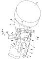
- a passenger car 1 comprises a wheel 2 and a in the area shown Bug 3 of a superstructure 4.
- the bow 3 is defined by skin sections 5, 6 which Are part of a bent part 8 extending between wheel cutouts 7.
- a space 9 of the bow 3-in delimited by the outer skin sections 5, 6
- Direction of travel in front of the wheel 2 - is a cooler 10 with an approximately rectangular Cross section installed, the longer sides 11 transverse to the vehicle longitudinal direction A-A run.
- the cooler 10 which is the charge insert is one not shown
- the charge air cooler optimizing the internal combustion engine is essentially vertical used.
- In the outer skin section 5 are air inlets 12, 13, including for the Cooler 10 provided.
- the outer skin section 6 has an outer wall 14, the one first extending transversely to the median longitudinal plane of the vehicle - not shown Has molded section 15 and a second upright molded section 16.
- the Molded sections 15, 16 are curved or convex. Between the first Molding section 15 and the second molding section 16, which are at an angle to each other run, a third mold section 17 is provided, which is designed as a curve.
- An outer contour 18 of the cooler 10 is adapted to the shaped sections 15, 16, 17, from the inside of room 9. Here is a constant Distance dimension Am between the shaped sections 15, 16, 17 and the outer contour 18 relatively small, as a result of which the cooler 10 is brought close to the outer skin section 6 is.
- the outer contour 18 comprises a first outer contour section 19 and a second Outer contour section 20, which is the outside of a supply line 21 of the cooler 10 form and along the first mold section 15 and the third mold section 17 run.
- the feed line 21 is on the mold section 16 opposite side 26 is provided with a connecting piece 27 through which one Turbocharger, not shown, air into the supply line 21 and the radiator body 24 arrives.
- the cooler body 24 has a distance from the feed line 21 Page 28 an outlet line 29, which also limits the radiator body 24 and on the side 26 includes a connection piece 30 through which cooled air to a Not shown intake system of the engine is directed.
- On Outer contour section 31 of the outlet line 29 is at a dash-dotted line fourth mold section 32 shown adapted to the outer wall 12, namely similar to the outer contour 18 to the corresponding mold sections.
- cooler 10 is attached to an existing one by suitable means Support structure 33 of the structure 4 attached.
Landscapes
- Engineering & Computer Science (AREA)
- Chemical & Material Sciences (AREA)
- Combustion & Propulsion (AREA)
- Transportation (AREA)
- Mechanical Engineering (AREA)
- Cooling, Air Intake And Gas Exhaust, And Fuel Tank Arrangements In Propulsion Units (AREA)
- Heat-Exchange Devices With Radiators And Conduit Assemblies (AREA)
Applications Claiming Priority (2)
| Application Number | Priority Date | Filing Date | Title |
|---|---|---|---|
| DE19923098A DE19923098C2 (de) | 1999-05-20 | 1999-05-20 | Kühler für Brennkraftmaschinen |
| DE19923098 | 1999-05-20 |
Publications (3)
| Publication Number | Publication Date |
|---|---|
| EP1053901A2 true EP1053901A2 (fr) | 2000-11-22 |
| EP1053901A3 EP1053901A3 (fr) | 2003-01-02 |
| EP1053901B1 EP1053901B1 (fr) | 2005-09-28 |
Family
ID=7908586
Family Applications (1)
| Application Number | Title | Priority Date | Filing Date |
|---|---|---|---|
| EP00106381A Expired - Lifetime EP1053901B1 (fr) | 1999-05-20 | 2000-03-24 | Radiateur pour moteur à combustion interne |
Country Status (4)
| Country | Link |
|---|---|
| US (1) | US6435295B1 (fr) |
| EP (1) | EP1053901B1 (fr) |
| JP (1) | JP2000351331A (fr) |
| DE (2) | DE19923098C2 (fr) |
Families Citing this family (8)
| Publication number | Priority date | Publication date | Assignee | Title |
|---|---|---|---|---|
| US6910529B2 (en) * | 2003-01-08 | 2005-06-28 | Ise Corporation | Vehicle rooftop engine cooling system |
| US20080053129A1 (en) * | 2003-01-08 | 2008-03-06 | Ise Corporation | Vehicle Rooftop Engine Cooling System and Method |
| US20060000429A1 (en) * | 2003-01-08 | 2006-01-05 | Stone Kevin T | Vehicle rooftop engine cooling system |
| US20070181442A1 (en) * | 2006-02-03 | 2007-08-09 | Applied Materials, Inc. | Method and apparatus for foam removal in an electrochemical mechanical substrate polishing process |
| DE102007028312A1 (de) * | 2007-06-20 | 2008-12-24 | Audi Ag | Kühleranordnung bei einem Personenkraftwagen |
| DE102008063497A1 (de) * | 2008-12-17 | 2010-06-24 | Audi Ag | Kraftwagen mit einem Heckmotor und einem Kühler |
| DE102010010398A1 (de) | 2010-03-05 | 2011-09-08 | GM Global Technology Operations LLC , (n. d. Ges. d. Staates Delaware) | Frontstruktur eines Kraftfahrzeugs |
| KR101231539B1 (ko) * | 2011-03-10 | 2013-02-07 | 기아자동차주식회사 | 주행풍유도덕트 및 이를 적용한 엔진룸구조 |
Citations (1)
| Publication number | Priority date | Publication date | Assignee | Title |
|---|---|---|---|---|
| DE3930076C1 (fr) | 1989-09-09 | 1991-02-14 | Mercedes-Benz Aktiengesellschaft, 7000 Stuttgart, De |
Family Cites Families (7)
| Publication number | Priority date | Publication date | Assignee | Title |
|---|---|---|---|---|
| GB279105A (en) * | 1926-10-15 | 1928-03-08 | Adolphe Kegresse | Improved method of mounting motor vehicle bonnets and radiators |
| DE2931812A1 (de) * | 1979-08-06 | 1981-02-26 | Heinrich Schlossmacher | Kuehlanlage fuer fahrzeugmotoren |
| JPH05170135A (ja) * | 1991-12-18 | 1993-07-09 | Mazda Motor Corp | 自動車の前部車体構造 |
| US5359969A (en) * | 1994-01-05 | 1994-11-01 | Caterpillar Inc. | Intermittent cooling fan control |
| US5460420A (en) * | 1994-11-09 | 1995-10-24 | Mccord Winn Textron | Compartmentized plastic bumper |
| JPH08270444A (ja) * | 1995-03-31 | 1996-10-15 | Hitachi Constr Mach Co Ltd | 建設機械の冷却構造 |
| DE19602186C1 (de) * | 1996-01-23 | 1997-05-22 | Porsche Ag | Kraftfahrzeug mit einer bugseitigen Kühleranordnung |
-
1999
- 1999-05-20 DE DE19923098A patent/DE19923098C2/de not_active Expired - Fee Related
-
2000
- 2000-03-24 EP EP00106381A patent/EP1053901B1/fr not_active Expired - Lifetime
- 2000-03-24 DE DE50011235T patent/DE50011235D1/de not_active Expired - Lifetime
- 2000-05-18 JP JP2000146430A patent/JP2000351331A/ja not_active Withdrawn
- 2000-05-22 US US09/576,855 patent/US6435295B1/en not_active Expired - Fee Related
Patent Citations (1)
| Publication number | Priority date | Publication date | Assignee | Title |
|---|---|---|---|---|
| DE3930076C1 (fr) | 1989-09-09 | 1991-02-14 | Mercedes-Benz Aktiengesellschaft, 7000 Stuttgart, De |
Also Published As
| Publication number | Publication date |
|---|---|
| EP1053901A3 (fr) | 2003-01-02 |
| EP1053901B1 (fr) | 2005-09-28 |
| DE19923098A1 (de) | 2000-11-30 |
| DE19923098C2 (de) | 2003-02-20 |
| JP2000351331A (ja) | 2000-12-19 |
| US6435295B1 (en) | 2002-08-20 |
| DE50011235D1 (de) | 2005-11-03 |
Similar Documents
| Publication | Publication Date | Title |
|---|---|---|
| DE69003407T2 (de) | Integriertes abgestimmtes Einlassystem. | |
| DE102007019539B4 (de) | Luftzufuhrvorrichtung für die Klimatisierung von Passagierräumen in Flugzeugen | |
| DE3321804C2 (de) | Vorrichtung zum Abführen von Warmluft aus dem Motorraum von Kraftwagen | |
| EP0175939A2 (fr) | Véhicule avec un canal d'entrée pour un refroidisseur d'air surchargé | |
| DE3338466A1 (de) | Kraftfahrzeug, insbesondere personenwagen | |
| DE112018000401T5 (de) | Kraftfahrzeug mit einem motorluftansaugungssystem und einer luftfilter-gehäuseanordnung, und verfahren zum leiten von luft an eine luftansaugung eines fahrzeugmotors | |
| DE102017129199B4 (de) | Luftstrommanagementsystem für ein Fahrzeug | |
| DE2740918A1 (de) | Brennkraftmaschine mit schallisolierender kapsel und ausserhalb der kapsel angeordnetem wasserkuehler | |
| DE1455760B2 (de) | Kuehlvorrichtung fuer ein gepanzertes fahrzeug | |
| EP1053901B1 (fr) | Radiateur pour moteur à combustion interne | |
| DE4244039C2 (de) | Kühlmodul für Verbrennungskraftmaschinen | |
| DE102016214827B4 (de) | Kraftfahrzeug mit rahmenartigem Montageträger als Teil einer Karosserie im Front-End-Bereich | |
| DE2527774A1 (de) | Luftansauganlage fuer brennkraftmaschinen | |
| DE3024312A1 (de) | Frontkonstruktion eines fahrzeuges | |
| DE102010051366A1 (de) | Tragstruktur für Karosserievorderbau eines Kraftfahrzeugs | |
| DE19943002C2 (de) | Kühleinrichtung für eine Brennkraftmaschine | |
| DE69400100T2 (de) | Schmierzufuhrvorrichtung in einer Brennkraftmaschine | |
| DE19830379A1 (de) | Rohrsystem, insbesondere Saugrohr einer Brennkraftmaschine | |
| DE19509002C3 (de) | Thermostatanbaupositionsstruktur | |
| DE3537744A1 (de) | Ansaugverteilerrohr | |
| DE19933283B4 (de) | Karosserievorderpartie | |
| DE2158638C3 (de) | Kraftfahrzeug, insbesondere Personenkraftwagen | |
| DE10340952B4 (de) | Kraftfahrzeug, vorzugsweise Sportwagen | |
| DE10307979B4 (de) | Kotflügel mit integriertem Luftzuführungssystem | |
| DE3531468C2 (de) | Luftzuführvorrichtung für den Motor eines Lastkraftwagens |
Legal Events
| Date | Code | Title | Description |
|---|---|---|---|
| PUAI | Public reference made under article 153(3) epc to a published international application that has entered the european phase |
Free format text: ORIGINAL CODE: 0009012 |
|
| AK | Designated contracting states |
Kind code of ref document: A2 Designated state(s): AT BE CH CY DE DK ES FI FR GB GR IE IT LI LU MC NL PT SE |
|
| AX | Request for extension of the european patent |
Free format text: AL;LT;LV;MK;RO;SI |
|
| PUAL | Search report despatched |
Free format text: ORIGINAL CODE: 0009013 |
|
| AK | Designated contracting states |
Kind code of ref document: A3 Designated state(s): AT BE CH CY DE DK ES FI FR GB GR IE IT LI LU MC NL PT SE |
|
| AX | Request for extension of the european patent |
Free format text: AL;LT;LV;MK;RO;SI |
|
| 17P | Request for examination filed |
Effective date: 20030702 |
|
| AKX | Designation fees paid |
Designated state(s): DE FR GB IT |
|
| 17Q | First examination report despatched |
Effective date: 20040525 |
|
| GRAP | Despatch of communication of intention to grant a patent |
Free format text: ORIGINAL CODE: EPIDOSNIGR1 |
|
| GRAS | Grant fee paid |
Free format text: ORIGINAL CODE: EPIDOSNIGR3 |
|
| GRAA | (expected) grant |
Free format text: ORIGINAL CODE: 0009210 |
|
| AK | Designated contracting states |
Kind code of ref document: B1 Designated state(s): DE FR GB IT |
|
| REG | Reference to a national code |
Ref country code: GB Ref legal event code: FG4D Free format text: NOT ENGLISH |
|
| REF | Corresponds to: |
Ref document number: 50011235 Country of ref document: DE Date of ref document: 20051103 Kind code of ref document: P |
|
| GBT | Gb: translation of ep patent filed (gb section 77(6)(a)/1977) |
Effective date: 20051221 |
|
| ET | Fr: translation filed | ||
| PLBE | No opposition filed within time limit |
Free format text: ORIGINAL CODE: 0009261 |
|
| STAA | Information on the status of an ep patent application or granted ep patent |
Free format text: STATUS: NO OPPOSITION FILED WITHIN TIME LIMIT |
|
| 26N | No opposition filed |
Effective date: 20060629 |
|
| PGFP | Annual fee paid to national office [announced via postgrant information from national office to epo] |
Ref country code: GB Payment date: 20090325 Year of fee payment: 10 |
|
| REG | Reference to a national code |
Ref country code: FR Ref legal event code: TP |
|
| PGFP | Annual fee paid to national office [announced via postgrant information from national office to epo] |
Ref country code: IT Payment date: 20090323 Year of fee payment: 10 |
|
| REG | Reference to a national code |
Ref country code: FR Ref legal event code: CD |
|
| GBPC | Gb: european patent ceased through non-payment of renewal fee |
Effective date: 20100324 |
|
| REG | Reference to a national code |
Ref country code: FR Ref legal event code: TP |
|
| PG25 | Lapsed in a contracting state [announced via postgrant information from national office to epo] |
Ref country code: IT Free format text: LAPSE BECAUSE OF NON-PAYMENT OF DUE FEES Effective date: 20100324 Ref country code: GB Free format text: LAPSE BECAUSE OF NON-PAYMENT OF DUE FEES Effective date: 20100324 |
|
| PGFP | Annual fee paid to national office [announced via postgrant information from national office to epo] |
Ref country code: FR Payment date: 20110404 Year of fee payment: 12 |
|
| REG | Reference to a national code |
Ref country code: FR Ref legal event code: ST Effective date: 20121130 |
|
| PG25 | Lapsed in a contracting state [announced via postgrant information from national office to epo] |
Ref country code: FR Free format text: LAPSE BECAUSE OF NON-PAYMENT OF DUE FEES Effective date: 20120402 |
|
| PGFP | Annual fee paid to national office [announced via postgrant information from national office to epo] |
Ref country code: DE Payment date: 20130307 Year of fee payment: 14 |
|
| REG | Reference to a national code |
Ref country code: DE Ref legal event code: R119 Ref document number: 50011235 Country of ref document: DE |
|
| REG | Reference to a national code |
Ref country code: DE Ref legal event code: R119 Ref document number: 50011235 Country of ref document: DE Effective date: 20141001 |
|
| PG25 | Lapsed in a contracting state [announced via postgrant information from national office to epo] |
Ref country code: DE Free format text: LAPSE BECAUSE OF NON-PAYMENT OF DUE FEES Effective date: 20141001 |