EP1053923A2 - Ralentisseur hydrodynamique et dispositif de commande électronique d'un ralentisseur hydrodynamique - Google Patents
Ralentisseur hydrodynamique et dispositif de commande électronique d'un ralentisseur hydrodynamique Download PDFInfo
- Publication number
- EP1053923A2 EP1053923A2 EP00110427A EP00110427A EP1053923A2 EP 1053923 A2 EP1053923 A2 EP 1053923A2 EP 00110427 A EP00110427 A EP 00110427A EP 00110427 A EP00110427 A EP 00110427A EP 1053923 A2 EP1053923 A2 EP 1053923A2
- Authority
- EP
- European Patent Office
- Prior art keywords
- control device
- hydrodynamic retarder
- housing
- retarder
- hydrodynamic
- Prior art date
- Legal status (The legal status is an assumption and is not a legal conclusion. Google has not performed a legal analysis and makes no representation as to the accuracy of the status listed.)
- Granted
Links
- 239000007788 liquid Substances 0.000 claims abstract description 5
- 238000001816 cooling Methods 0.000 claims description 22
- 230000008878 coupling Effects 0.000 claims description 8
- 238000010168 coupling process Methods 0.000 claims description 8
- 238000005859 coupling reaction Methods 0.000 claims description 8
- 239000011810 insulating material Substances 0.000 claims description 5
- 239000000853 adhesive Substances 0.000 claims description 3
- 230000001070 adhesive effect Effects 0.000 claims description 3
- 239000011248 coating agent Substances 0.000 claims description 2
- 238000000576 coating method Methods 0.000 claims description 2
- 239000002826 coolant Substances 0.000 description 12
- RYGMFSIKBFXOCR-UHFFFAOYSA-N Copper Chemical compound [Cu] RYGMFSIKBFXOCR-UHFFFAOYSA-N 0.000 description 4
- 238000012546 transfer Methods 0.000 description 4
- 230000005540 biological transmission Effects 0.000 description 3
- 230000008859 change Effects 0.000 description 3
- 230000001276 controlling effect Effects 0.000 description 3
- 229910052802 copper Inorganic materials 0.000 description 3
- 239000010949 copper Substances 0.000 description 3
- 239000000463 material Substances 0.000 description 3
- 230000008901 benefit Effects 0.000 description 2
- 239000004020 conductor Substances 0.000 description 2
- 239000000498 cooling water Substances 0.000 description 2
- 238000013461 design Methods 0.000 description 2
- 238000001514 detection method Methods 0.000 description 2
- 239000012530 fluid Substances 0.000 description 2
- 230000017525 heat dissipation Effects 0.000 description 2
- 238000009434 installation Methods 0.000 description 2
- 230000010354 integration Effects 0.000 description 2
- 238000000034 method Methods 0.000 description 2
- 239000012811 non-conductive material Substances 0.000 description 2
- 230000008569 process Effects 0.000 description 2
- 230000008672 reprogramming Effects 0.000 description 2
- 239000000725 suspension Substances 0.000 description 2
- 230000007704 transition Effects 0.000 description 2
- -1 For example Substances 0.000 description 1
- 229920000544 Gore-Tex Polymers 0.000 description 1
- 206010041953 Staring Diseases 0.000 description 1
- 239000003795 chemical substances by application Substances 0.000 description 1
- 238000005352 clarification Methods 0.000 description 1
- 230000020169 heat generation Effects 0.000 description 1
- 239000000314 lubricant Substances 0.000 description 1
- 238000004519 manufacturing process Methods 0.000 description 1
- 239000012528 membrane Substances 0.000 description 1
- 230000035515 penetration Effects 0.000 description 1
- 238000004886 process control Methods 0.000 description 1
- 238000012545 processing Methods 0.000 description 1
- 230000001105 regulatory effect Effects 0.000 description 1
- 239000000126 substance Substances 0.000 description 1
- 238000012360 testing method Methods 0.000 description 1
- 238000009423 ventilation Methods 0.000 description 1
Images



Classifications
-
- B—PERFORMING OPERATIONS; TRANSPORTING
- B60—VEHICLES IN GENERAL
- B60T—VEHICLE BRAKE CONTROL SYSTEMS OR PARTS THEREOF; BRAKE CONTROL SYSTEMS OR PARTS THEREOF, IN GENERAL; ARRANGEMENT OF BRAKING ELEMENTS ON VEHICLES IN GENERAL; PORTABLE DEVICES FOR PREVENTING UNWANTED MOVEMENT OF VEHICLES; VEHICLE MODIFICATIONS TO FACILITATE COOLING OF BRAKES
- B60T1/00—Arrangements of braking elements, i.e. of those parts where braking effect occurs specially for vehicles
- B60T1/02—Arrangements of braking elements, i.e. of those parts where braking effect occurs specially for vehicles acting by retarding wheels
- B60T1/08—Arrangements of braking elements, i.e. of those parts where braking effect occurs specially for vehicles acting by retarding wheels using fluid or powdered medium
- B60T1/087—Arrangements of braking elements, i.e. of those parts where braking effect occurs specially for vehicles acting by retarding wheels using fluid or powdered medium in hydrodynamic, i.e. non-positive displacement, retarders
-
- B—PERFORMING OPERATIONS; TRANSPORTING
- B60—VEHICLES IN GENERAL
- B60T—VEHICLE BRAKE CONTROL SYSTEMS OR PARTS THEREOF; BRAKE CONTROL SYSTEMS OR PARTS THEREOF, IN GENERAL; ARRANGEMENT OF BRAKING ELEMENTS ON VEHICLES IN GENERAL; PORTABLE DEVICES FOR PREVENTING UNWANTED MOVEMENT OF VEHICLES; VEHICLE MODIFICATIONS TO FACILITATE COOLING OF BRAKES
- B60T10/00—Control or regulation for continuous braking making use of fluid or powdered medium, e.g. for use when descending a long slope
- B60T10/02—Control or regulation for continuous braking making use of fluid or powdered medium, e.g. for use when descending a long slope with hydrodynamic brake
Definitions
- the invention relates to a hydrodynamic retarder, in particular with the features from the preamble of claim 1. Furthermore, a Device for the electronic control of a hydrodynamic Retarders, in particular retarder control devices.
- retarder controls are usually one in the cab Vehicle near the control element for the retarder, such as described, for example, in the case of DE 43 41 213.
- For Connection with the individual sensors and actuators are corresponding long cables and a large number of plug connections are required.
- retarder controls are also known become, which can be integrated into the vehicle management system, such as described for example in WO 94/28745.
- a disadvantage of the known retarder control devices is that the controls are always set identically for a retarder of the same type are, for example, to ensure easy interchangeability, i.e. however, that the known hydrodynamic tolerances are not excluded can be. Such retarder control devices are therefore not on the retarder individually installed in the vehicle.
- the retarder control devices become a retarder of a certain type, when replacing the retarder the Control, for example the electronic control unit (ECU), be reprogrammed accordingly.
- ECU electronice control unit
- the invention was therefore based on the object of a hydrodynamic Retarder or an electronic device for Retarder control specify the disadvantages previously shown avoids, that is, allows easy replacement of the retarder and the retarder control on the individual, in the vehicle built-in retarder is matched. Furthermore, the necessary ones Line connections, their length and the required To reduce plug connections.
- a hydrodynamic retarder includes a retarder housing and a control device assigned to it, in particular retarder control device, comprising at least one Control device, in particular retarder control device, the Control device arranged in the retarder housing.
- the control unit which the for Control of the hydrodynamic retarder required sizes fed and processed, and that from the input variables to be formed according to the desired control process Control variables are output.
- This usually includes a plurality electrical components, which according to the Processing of input variables assigned to each other and with each other are coupled.
- a plurality of the electronic ones Components arranged on at least one carrier plate and by one Control device housing enclosed. There is the possibility that the carrier plate completely in
- Control device housing is integrated or at least one Partial wall area of the control device housing forms.
- the solution according to the invention offers the advantage of an increased Reliability because of the number and length required for electrical Coupling required line connections to the conventional solutions is significantly lower. Furthermore, by the arrangement of the control device in the hydrodynamic retarder an individual adjustment of the control device to the respective hydrodynamic retarder possible without having to replace the hydrodynamic retarder reprogramming the Control device must be made.
- the unique assignment of hydrodynamic retarder and electronic control device enables simplification of logistics.
- the structural unity of Control device and hydrodynamic retarder enables Creation of a testable unit of control device, control hydraulics, Actuators and sensors of the hydrodynamic retarder, the Control device already on the detectable during a test process Tolerances is customizable.
- control device is one Assigned housing, which is preferably against hydraulic fluid, For example, oil and / or another liquid is tight.
- the control device can then in the oil sump of the hydrodynamic Retarders are arranged. This gives you the opportunity to electronic components of the control device at least one indirect cooling by the in the operating fluid or oil sump of the Equipment located in hydrodynamic retarders.
- the oil density Execution of the housing requires the realization of the electrical Connection between the control device and the, for detecting the, the current filling state at least indirectly characterizing variables and / or the driver's request for the generation of a specific one Braking torque and / or other boundary conditions required Sensors of the control device and by means of the control device actuators to be actuated for actuating the individual actuating devices of the hydrodynamic retarder, for example one Pressure generating device for setting a specific to the Mirror of a resource sump acting in a resource tank Pressure and / or for specifying input variables by a higher-level control or regulating device, one appropriately designed bushing on the housing.
- the individual contact elements or lines in one electrically non-conductive and liquid-tight material embedded by guided the control device housing, so that the penetration of harmful substances, such as oil, in the Control device housing is prevented.
- control device in the lower area of the installation position Retarders and the provision of an appropriate housing allows es, the sensors for detecting at least one, the current one Functional state of the hydrodynamic retarder to a certain Time at least indirectly describing sizes also in the range below the retarder symmetry line, which corresponds to the axis of rotation, to arrange and thus the entire control device relatively compact to execute.
- the electronic control device which in Housing of the hydrodynamic retarder is integrated, thermally is decoupled from this, for example by a heat insulating Intermediate layer.
- the housing of the electronic control device is thereby, for example, when arranged in the oil sump of the hydrodynamic Retarders against the oil sump with a heat-insulating medium excessive heat transfer from hot oil to electronic Components protected.
- the electronic control device not only to be decoupled thermally from the hydrodynamic retarder but also vibration engineering, for example, that the electronic control device damped in the vibration hydrodynamic retarder is suspended.
- the electronic control device comprises at least one input, which with the, for at least indirect detection of an actual value of a Size for a current driver request and / or a driving condition provided sensors and / or a further control device can be coupled. Furthermore, at least one output is provided, which with the actuators to change the operating state of the hydrodynamic retarder, for example the actuator for Change in pressure on the equipment sump that can be coupled.
- the actuators to change the operating state of the hydrodynamic retarder, for example the actuator for Change in pressure on the equipment sump that can be coupled.
- the Device for cable entry to realize a transition from Cables from one with a lubricant or equipment or the like at least partially filled or containing residues and by a Housing at least partially enclosed space outside of the space includes one made of electrically non-conductive material existing insulating body for the implementation of the cable elements, which of an electrically non-conductive and against liquids impervious material.
- the connection between the electrical Contacts of the connecting lines or connecting cables and the electronic components of the control device preferably such that they are designed as spring contacts to also in the event of interference, a safe contact of the connections between the individual connecting lines and the electrical components of the Realize control device.
- Another version is to use rigid conductor tracks, e.g. made of copper to use, which is the connection between the sensors and Actuators and the electrical elements of the control device and the Produce the housing of the control device.
- the connection to the second control device is arranged in the area of the retarder housing and preferably in the form of a, possibly simple, plug connection is performed.
- the ingress of oil vapors is Moisture and other harmful media in the control device Ventilation of the control device with a special cover in the housing the control device provided.
- the inner wall of the Housing of the control device of the hydrodynamic retarder additionally to be provided with a membrane which, for example, consists of Goretex exists.
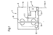
- FIG. 1 illustrates a schematically simplified representation hydrodynamic retarder 1, which to realize different Modes of operation, especially filling and emptying Control device 2 is assigned.
- the control device 2 comprises one Control device 3, which is generally also referred to as a control device becomes.
- the control device 3 is according to the invention in the housing 4 of the hydrodynamic retarder 1 integrated.
- the control device 3 has at least one input 5.1 and one output 6.1. Preferably a plurality of inputs 5.1 to 5.n are provided, which with Sensors 7.1 to 7.n when integrating the hydrodynamic retarder 1 in a vehicle for at least indirect detection of the current one Degree of filling and / or one, the current driver request for generation of a certain braking torque at least indirectly characterizing Size can be coupled.
- control device 3 In the arrangement of the control device 3 shown in FIG the housing inner wall 9 in the installed position of the hydrodynamic Retarders 1 viewed on a side wall 10 are also concerned an example. Other arrangement options are conceivable. Preferably however, an arrangement as shown in FIG. 2 is selected.
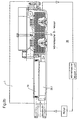
- the basic structure essentially corresponds to that in FIG. 1 described, which is why the same reference numerals for the same elements be used.
- the control device 3 is arranged in Installation position of the hydrodynamic retarder viewed in the lower area, preferably in the oil sump of the hydrodynamic retarder 1.
- Die Control device 3 comprises a large number of electrical components 12, which are arranged on at least one carrier plate 30 and which in a separate housing 14 are integrated.
- the housing 14 of the Control device 3 is designed to be liquid-tight.
- connection between the inputs 5.1 to 5.n of the control device and the sensors 7.1 to 7.n or a parent Driving control and the outputs 6.1 to 6.n with the actuators 8.1 to 8.n are corresponding line connections 15.1 to 15.n for the Coupling between sensors 7.1 to 7.n and inputs 5.1 to 5.n and 16.1 to 16.n for the coupling between the outputs 6.1 and 6.n. and the actuators 8.1 and 8.n provided.
- These lines can be used as flexible cable connections or as rigid lines, for example in In the form of copper pipes.
- Bushings 17 and 18 are provided on the housing 14.
- the implementation 17 serves to guide the line connections between the Sensors 7.1 to 7.n and the inputs 5.1 to 5.n of the control device 3 the implementation of the transition of lines 16.1 to 16.n to Connection between the outputs 6.1 to 6.n with the actuators 8.1 to 8.n.
- a further bushing 18 is provided, which one Oil-tight passage of the line connection between one higher-level control device, preferably the control device 20 to implement vehicle management with the electronic Control device 3 allows.
- This control device 20 also includes a control device 21 with at least one input 22.1 to 22.n and an output 23.1 to 23.n, at least one output 23.n with the Control device 3 of the hydrodynamic retarder 1 can be coupled.
- the Tightness against liquids can lead to the implementation different ways can be realized.
- the connector between the Connection lines between sensors 7.1 to 7.n and the electronic Control device 3 or the actuators 8.1 to 8.n and the electronic control device 3 and the parent Control device 20 and the control device 3 can, as in the Figure 2 shown, can be realized in the housing 14.
- the control device 3 For this purpose comprises a carrier plate 30 on which a plurality of electronic Components are arranged.
- the carrier plate forms, for example a circuit board provided with electrical plug contacts 31.1 to 31.n.
- the carrier element 30 is preferably thermally conductive to the bottom 32 of the Housing 14 connected. This is done, for example, by means of a Adhesive connection realized. Another possibility is the assignment from heat-insulating material to the housing 14 Housing 14 in particular in the area of its pointing towards the oil sump 11 Outside, here the side surfaces 33.1 to 33.3 with a heat-insulating material can be coated. Another possibility consists in closing the housing wall from heat-insulating material shape.
- FIG. 2b illustrates in a schematically simplified representation using of the housing 14 of the control device 3 in accordance with FIG. 2a Possibility of allocating funds to at least indirect ones Heat dissipation from the electrical components of the control device 3.
- the walls 34 of the housing 14 Coolant guide lines 35.1 to 35.n provided.
- the Coolant guide lines 35.1 to 35.n are in the inlet a cooling device or a heat exchanger 37.
- FIG. 2c discloses an embodiment in which the Coolant guide lines 35.1 to 35.n in the walls 34 of the housing 14 into the coolant circuit 38 of the hydrodynamic retarder 1 are integrated.
- Another possibility, not shown here in detail consists of a separate cooling circuit for the control device 3 assign.
- Figure 3 illustrates in a schematically simplified representation Coupling of the electrical control device 2 of the hydrodynamic Retarder 1 with the control device 20 of the vehicle the configuration a device for electronic control of the retarder 19.
- the retarder 1 and the control device 20 for the Vehicle management which in the present case is an electronic control unit is shown. This is removed from the vehicle Retarder 1 arranged.
- the retarder 1 can be installed anywhere in the vehicle and is the term includes all types of retarder units.
- the programs for the whole Vehicle management can include, the control device 3 is over at least one signal line 39 is electrically connected.
- the second control device for the Gear unit instead of directly with the control device 20 for implementation vehicle management also with an interface, for example a CAN bus for vehicle management.
- the Connection line 39 can the corresponding control signals from the Control device 20 or the interface to the Control device 3 are transmitted, as well as processed signals from the control device 3 to the control device 20 or the Interface.
- Others are indicated on the control device 20 Signal lines 26.1 to 26.n to other vehicle components, for example to the prime mover or to other braking systems.
- the present invention thus becomes an arrangement for the first time created with which an exchange of the Control devices of the hydrodynamic retarder or one Reprogramming the same when replacing the hydrodynamic Retarders or individual elements of the hydrodynamic retarder are omitted.
Landscapes
- Engineering & Computer Science (AREA)
- Physics & Mathematics (AREA)
- Fluid Mechanics (AREA)
- Transportation (AREA)
- Mechanical Engineering (AREA)
- Transmission Of Braking Force In Braking Systems (AREA)
- Braking Arrangements (AREA)
Applications Claiming Priority (2)
| Application Number | Priority Date | Filing Date | Title |
|---|---|---|---|
| DE19923022A DE19923022A1 (de) | 1999-05-19 | 1999-05-19 | Hydrodynamischer Retarder und Vorrichtung zur elektronischen Steuerung eines hydrodynamischen Retarders |
| DE19923022 | 1999-05-19 |
Publications (3)
| Publication Number | Publication Date |
|---|---|
| EP1053923A2 true EP1053923A2 (fr) | 2000-11-22 |
| EP1053923A3 EP1053923A3 (fr) | 2002-08-28 |
| EP1053923B1 EP1053923B1 (fr) | 2003-12-10 |
Family
ID=7908545
Family Applications (1)
| Application Number | Title | Priority Date | Filing Date |
|---|---|---|---|
| EP00110427A Expired - Lifetime EP1053923B1 (fr) | 1999-05-19 | 2000-05-16 | Ralentisseur hydrodynamique et dispositif de commande électronique d'un ralentisseur hydrodynamique |
Country Status (3)
| Country | Link |
|---|---|
| EP (1) | EP1053923B1 (fr) |
| AT (1) | ATE256021T1 (fr) |
| DE (2) | DE19923022A1 (fr) |
Cited By (5)
| Publication number | Priority date | Publication date | Assignee | Title |
|---|---|---|---|---|
| WO2002087940A1 (fr) * | 2001-04-27 | 2002-11-07 | Volvo Lastvagnar Ab | Ralentisseur hydraulique pour vehicules |
| WO2009121691A1 (fr) * | 2008-04-01 | 2009-10-08 | Zf Friedrichshafen Ag | Boîtier de commande pour commande de ralentisseur hydraulique |
| EP1750027A3 (fr) * | 2005-08-05 | 2009-11-25 | Voith Turbo GmbH & Co. KG | Chaîne cinématique |
| DE10058112B4 (de) * | 2000-11-23 | 2010-08-05 | Zf Friedrichshafen Ag | Automatgetriebe |
| CN114454857A (zh) * | 2021-12-23 | 2022-05-10 | 陕西法士特齿轮有限责任公司 | 一种响应电子制动系统制动请求的缓速器控制方法及系统 |
Families Citing this family (2)
| Publication number | Priority date | Publication date | Assignee | Title |
|---|---|---|---|---|
| DE102004034734A1 (de) * | 2004-07-17 | 2006-02-16 | Zf Friedrichshafen Ag | Anordnung der elektronischen Retardersteuerung (ECU) |
| DE102009050512B3 (de) * | 2009-10-23 | 2011-05-05 | Voith Patent Gmbh | Schalt- und Steuergerät sowie Antriebsstrang einer hydrodynamischen Maschine |
Citations (2)
| Publication number | Priority date | Publication date | Assignee | Title |
|---|---|---|---|---|
| EP0291887A2 (fr) | 1987-05-20 | 1988-11-23 | Csepel Autogyár | Procédé de commande d'un ralentisseur hydrodynamique dans un véhicule à moteur |
| WO1994028745A1 (fr) | 1993-06-11 | 1994-12-22 | Asea Brown Boveri Ab | Dispositif de traitement haute pression de substances |
Family Cites Families (5)
| Publication number | Priority date | Publication date | Assignee | Title |
|---|---|---|---|---|
| WO1994027845A1 (fr) * | 1992-05-22 | 1994-12-08 | Scania Cv Aktiebolag | Procede et systeme de regulation servant a limiter l'effet de freinage produit par un frein auxiliaire hydrodynamique dans un vehicule a moteur |
| DE4310898C1 (de) * | 1993-04-02 | 1994-08-18 | Voith Turbo Kg | Hydrodynamischer Retarder |
| DE4341213C2 (de) * | 1993-12-03 | 1995-07-27 | Voith Turbo Kg | Steuerung zur Geschwindigkeitsbeeinflussung eines Fahrzeuges |
| DE4439368A1 (de) * | 1994-11-04 | 1995-06-14 | Voith Turbo Kg | Wärmetauscher, insbesondere für einen hydrodynamischen Retarder |
| DE19813015A1 (de) * | 1998-03-25 | 1999-10-07 | Voith Turbo Kg | Am Retarder angeordnete Steuereinheit und/oder Eigenschaftsspeicher |
-
1999
- 1999-05-19 DE DE19923022A patent/DE19923022A1/de not_active Withdrawn
-
2000
- 2000-05-16 EP EP00110427A patent/EP1053923B1/fr not_active Expired - Lifetime
- 2000-05-16 DE DE50004696T patent/DE50004696D1/de not_active Expired - Lifetime
- 2000-05-16 AT AT00110427T patent/ATE256021T1/de active
Patent Citations (2)
| Publication number | Priority date | Publication date | Assignee | Title |
|---|---|---|---|---|
| EP0291887A2 (fr) | 1987-05-20 | 1988-11-23 | Csepel Autogyár | Procédé de commande d'un ralentisseur hydrodynamique dans un véhicule à moteur |
| WO1994028745A1 (fr) | 1993-06-11 | 1994-12-22 | Asea Brown Boveri Ab | Dispositif de traitement haute pression de substances |
Cited By (6)
| Publication number | Priority date | Publication date | Assignee | Title |
|---|---|---|---|---|
| DE10058112B4 (de) * | 2000-11-23 | 2010-08-05 | Zf Friedrichshafen Ag | Automatgetriebe |
| WO2002087940A1 (fr) * | 2001-04-27 | 2002-11-07 | Volvo Lastvagnar Ab | Ralentisseur hydraulique pour vehicules |
| EP1750027A3 (fr) * | 2005-08-05 | 2009-11-25 | Voith Turbo GmbH & Co. KG | Chaîne cinématique |
| WO2009121691A1 (fr) * | 2008-04-01 | 2009-10-08 | Zf Friedrichshafen Ag | Boîtier de commande pour commande de ralentisseur hydraulique |
| CN114454857A (zh) * | 2021-12-23 | 2022-05-10 | 陕西法士特齿轮有限责任公司 | 一种响应电子制动系统制动请求的缓速器控制方法及系统 |
| CN114454857B (zh) * | 2021-12-23 | 2023-01-06 | 陕西法士特齿轮有限责任公司 | 一种响应电子制动系统制动请求的缓速器控制方法及系统 |
Also Published As
| Publication number | Publication date |
|---|---|
| ATE256021T1 (de) | 2003-12-15 |
| DE19923022A1 (de) | 2000-11-30 |
| DE50004696D1 (de) | 2004-01-22 |
| EP1053923B1 (fr) | 2003-12-10 |
| EP1053923A3 (fr) | 2002-08-28 |
Similar Documents
| Publication | Publication Date | Title |
|---|---|---|
| EP1222414A1 (fr) | Ensemble de transmission et plate-forme de commande utilisee dans un tel ensemble | |
| DE69707151T2 (de) | Verbesserungen in verbindung mit kraftverstärkten lenkvorrichtungen | |
| EP1230500B1 (fr) | Boite automatique d'un vehicule avec connexion a fiche electrique | |
| DE9307228U1 (de) | Steuersystem, insbesondere Getriebesteuerungssystem für ein Kraftfahrzeug | |
| EP2789216B1 (fr) | Module de commande de boîte de vitesses | |
| EP1053923B1 (fr) | Ralentisseur hydrodynamique et dispositif de commande électronique d'un ralentisseur hydrodynamique | |
| EP1135635A1 (fr) | Refroidissement d'un appareil de commande de boite de vitesses d'automobile | |
| DE19529665C2 (de) | Steuereinrichtung für ein Kraftfahrzeug mit einem automatischen Getriebe | |
| EP1259401B1 (fr) | Module et dispositif pour l'execution de fonctions de commande ou de regulation pour un vehicule | |
| EP3427557B1 (fr) | Appareil de commande | |
| DE19923023A1 (de) | Getriebebaueinheit und Vorrichtung zur elektronischen Steuerung einer Getriebebaueinheit | |
| WO2018171837A1 (fr) | Module d'actionnement pour embrayages et systèmes de sélection de vitesse et boîte de vitesses comprenant un module d'actionnement | |
| WO1998010489A1 (fr) | Connecteur pour jonction electrique etanche a l'humidite | |
| DE102007032594B4 (de) | Steuervorrichtung und Verfahren zur Herstellung einer Steuervorrichtung | |
| DE102010019027B4 (de) | Bauteil für eine Einrichtung zum Aufnehmen von Hydraulikfluid für ein Getriebe eines Kraftwagens | |
| DE102013212265A1 (de) | Elektronische Einheit und Verfahren zur Herstellung einer elektronischen Einheit | |
| DE102005020926B4 (de) | Steuergerät für ein Kraftfahrzeuggetriebe | |
| WO2023061644A1 (fr) | Réservoir d'agent de refroidissement, système de conduction d'agent de refroidissement et véhicule automobile | |
| DE102018108562A1 (de) | Stellantrieb, Heizkreisverteiler und Verfahren zur Montage des Stellantriebes in einem solchen Heizkreisverteiler | |
| DE60312569T2 (de) | Schaltungsarchitektur eines gangschalters für ein automatisches getriebe | |
| EP0953489B1 (fr) | Unité de commande et / ou banc de mémoire pour un ralentisseur | |
| DE102013212164A1 (de) | Anordnung zur Getriebesteuerung | |
| DE19646444B4 (de) | Elektrohydraulisches System | |
| EP1087155B1 (fr) | Dispositif de commande pour une boíte de vitesses | |
| DE102023210657A1 (de) | Kühlsystem für elektronische Steuergeräte eines Fahrzeugs |
Legal Events
| Date | Code | Title | Description |
|---|---|---|---|
| PUAI | Public reference made under article 153(3) epc to a published international application that has entered the european phase |
Free format text: ORIGINAL CODE: 0009012 |
|
| AK | Designated contracting states |
Kind code of ref document: A2 Designated state(s): AT BE CH CY DE DK ES FI FR GB GR IE IT LI LU MC NL PT SE |
|
| AX | Request for extension of the european patent |
Free format text: AL;LT;LV;MK;RO;SI |
|
| PUAL | Search report despatched |
Free format text: ORIGINAL CODE: 0009013 |
|
| AK | Designated contracting states |
Kind code of ref document: A3 Designated state(s): AT BE CH CY DE DK ES FI FR GB GR IE IT LI LU MC NL PT SE |
|
| AX | Request for extension of the european patent |
Free format text: AL;LT;LV;MK;RO;SI |
|
| 17P | Request for examination filed |
Effective date: 20020918 |
|
| 17Q | First examination report despatched |
Effective date: 20021031 |
|
| AKX | Designation fees paid |
Designated state(s): AT DE FR GB SE |
|
| GRAH | Despatch of communication of intention to grant a patent |
Free format text: ORIGINAL CODE: EPIDOS IGRA |
|
| GRAS | Grant fee paid |
Free format text: ORIGINAL CODE: EPIDOSNIGR3 |
|
| GRAA | (expected) grant |
Free format text: ORIGINAL CODE: 0009210 |
|
| AK | Designated contracting states |
Kind code of ref document: B1 Designated state(s): AT DE FR GB SE |
|
| REG | Reference to a national code |
Ref country code: GB Ref legal event code: FG4D Free format text: NOT ENGLISH |
|
| GBT | Gb: translation of ep patent filed (gb section 77(6)(a)/1977) |
Effective date: 20031210 |
|
| REG | Reference to a national code |
Ref country code: IE Ref legal event code: FG4D Free format text: GERMAN |
|
| REF | Corresponds to: |
Ref document number: 50004696 Country of ref document: DE Date of ref document: 20040122 Kind code of ref document: P |
|
| REG | Reference to a national code |
Ref country code: SE Ref legal event code: TRGR |
|
| REG | Reference to a national code |
Ref country code: IE Ref legal event code: FD4D |
|
| ET | Fr: translation filed | ||
| PLBE | No opposition filed within time limit |
Free format text: ORIGINAL CODE: 0009261 |
|
| STAA | Information on the status of an ep patent application or granted ep patent |
Free format text: STATUS: NO OPPOSITION FILED WITHIN TIME LIMIT |
|
| 26N | No opposition filed |
Effective date: 20040913 |
|
| PGFP | Annual fee paid to national office [announced via postgrant information from national office to epo] |
Ref country code: AT Payment date: 20120523 Year of fee payment: 13 |
|
| PGFP | Annual fee paid to national office [announced via postgrant information from national office to epo] |
Ref country code: GB Payment date: 20130521 Year of fee payment: 14 Ref country code: DE Payment date: 20130530 Year of fee payment: 14 Ref country code: SE Payment date: 20130521 Year of fee payment: 14 |
|
| PGFP | Annual fee paid to national office [announced via postgrant information from national office to epo] |
Ref country code: FR Payment date: 20130605 Year of fee payment: 14 |
|
| REG | Reference to a national code |
Ref country code: DE Ref legal event code: R119 Ref document number: 50004696 Country of ref document: DE |
|
| REG | Reference to a national code |
Ref country code: AT Ref legal event code: MM01 Ref document number: 256021 Country of ref document: AT Kind code of ref document: T Effective date: 20140516 |
|
| GBPC | Gb: european patent ceased through non-payment of renewal fee |
Effective date: 20140516 |
|
| PG25 | Lapsed in a contracting state [announced via postgrant information from national office to epo] |
Ref country code: SE Free format text: LAPSE BECAUSE OF NON-PAYMENT OF DUE FEES Effective date: 20140517 |
|
| REG | Reference to a national code |
Ref country code: SE Ref legal event code: EUG |
|
| PG25 | Lapsed in a contracting state [announced via postgrant information from national office to epo] |
Ref country code: AT Free format text: LAPSE BECAUSE OF NON-PAYMENT OF DUE FEES Effective date: 20140516 |
|
| REG | Reference to a national code |
Ref country code: FR Ref legal event code: ST Effective date: 20150130 |
|
| REG | Reference to a national code |
Ref country code: DE Ref legal event code: R119 Ref document number: 50004696 Country of ref document: DE Effective date: 20141202 |
|
| PG25 | Lapsed in a contracting state [announced via postgrant information from national office to epo] |
Ref country code: DE Free format text: LAPSE BECAUSE OF NON-PAYMENT OF DUE FEES Effective date: 20141202 |
|
| PG25 | Lapsed in a contracting state [announced via postgrant information from national office to epo] |
Ref country code: GB Free format text: LAPSE BECAUSE OF NON-PAYMENT OF DUE FEES Effective date: 20140516 Ref country code: FR Free format text: LAPSE BECAUSE OF NON-PAYMENT OF DUE FEES Effective date: 20140602 |