EP1053965A2 - Cylinder arrangement for a folding apparatus of a rotary printing machine - Google Patents
Cylinder arrangement for a folding apparatus of a rotary printing machine Download PDFInfo
- Publication number
- EP1053965A2 EP1053965A2 EP00109008A EP00109008A EP1053965A2 EP 1053965 A2 EP1053965 A2 EP 1053965A2 EP 00109008 A EP00109008 A EP 00109008A EP 00109008 A EP00109008 A EP 00109008A EP 1053965 A2 EP1053965 A2 EP 1053965A2
- Authority
- EP
- European Patent Office
- Prior art keywords
- paper
- cylinder
- layer
- guiding
- cylinder according
- Prior art date
- Legal status (The legal status is an assumption and is not a legal conclusion. Google has not performed a legal analysis and makes no representation as to the accuracy of the status listed.)
- Granted
Links
Images
Classifications
-
- B—PERFORMING OPERATIONS; TRANSPORTING
- B65—CONVEYING; PACKING; STORING; HANDLING THIN OR FILAMENTARY MATERIAL
- B65H—HANDLING THIN OR FILAMENTARY MATERIAL, e.g. SHEETS, WEBS, CABLES
- B65H45/00—Folding thin material
- B65H45/12—Folding articles or webs with application of pressure to define or form crease lines
- B65H45/16—Rotary folders
- B65H45/162—Rotary folders with folding jaw cylinders
- B65H45/166—Rotary folders with folding jaw cylinders having an adjustable circumference
-
- B—PERFORMING OPERATIONS; TRANSPORTING
- B65—CONVEYING; PACKING; STORING; HANDLING THIN OR FILAMENTARY MATERIAL
- B65H—HANDLING THIN OR FILAMENTARY MATERIAL, e.g. SHEETS, WEBS, CABLES
- B65H2401/00—Materials used for the handling apparatus or parts thereof; Properties thereof
- B65H2401/10—Materials
-
- B—PERFORMING OPERATIONS; TRANSPORTING
- B65—CONVEYING; PACKING; STORING; HANDLING THIN OR FILAMENTARY MATERIAL
- B65H—HANDLING THIN OR FILAMENTARY MATERIAL, e.g. SHEETS, WEBS, CABLES
- B65H2404/00—Parts for transporting or guiding the handled material
- B65H2404/40—Shafts, cylinders, drums, spindles
- B65H2404/41—Details of cross section profile
-
- B—PERFORMING OPERATIONS; TRANSPORTING
- B65—CONVEYING; PACKING; STORING; HANDLING THIN OR FILAMENTARY MATERIAL
- B65H—HANDLING THIN OR FILAMENTARY MATERIAL, e.g. SHEETS, WEBS, CABLES
- B65H2404/00—Parts for transporting or guiding the handled material
- B65H2404/50—Surface of the elements in contact with the forwarded or guided material
- B65H2404/55—Built-up surface, e.g. arrangement for attaching the surface to the forwarding or guiding element
-
- B—PERFORMING OPERATIONS; TRANSPORTING
- B65—CONVEYING; PACKING; STORING; HANDLING THIN OR FILAMENTARY MATERIAL
- B65H—HANDLING THIN OR FILAMENTARY MATERIAL, e.g. SHEETS, WEBS, CABLES
- B65H2404/00—Parts for transporting or guiding the handled material
- B65H2404/50—Surface of the elements in contact with the forwarded or guided material
- B65H2404/55—Built-up surface, e.g. arrangement for attaching the surface to the forwarding or guiding element
- B65H2404/551—Non permanent attachment, i.e. allowing interchange ability of the surface
-
- B—PERFORMING OPERATIONS; TRANSPORTING
- B65—CONVEYING; PACKING; STORING; HANDLING THIN OR FILAMENTARY MATERIAL
- B65H—HANDLING THIN OR FILAMENTARY MATERIAL, e.g. SHEETS, WEBS, CABLES
- B65H2404/00—Parts for transporting or guiding the handled material
- B65H2404/50—Surface of the elements in contact with the forwarded or guided material
- B65H2404/55—Built-up surface, e.g. arrangement for attaching the surface to the forwarding or guiding element
- B65H2404/551—Non permanent attachment, i.e. allowing interchange ability of the surface
- B65H2404/5512—Non permanent attachment, i.e. allowing interchange ability of the surface covering only a part of the surface
-
- B—PERFORMING OPERATIONS; TRANSPORTING
- B65—CONVEYING; PACKING; STORING; HANDLING THIN OR FILAMENTARY MATERIAL
- B65H—HANDLING THIN OR FILAMENTARY MATERIAL, e.g. SHEETS, WEBS, CABLES
- B65H2404/00—Parts for transporting or guiding the handled material
- B65H2404/50—Surface of the elements in contact with the forwarded or guided material
- B65H2404/56—Flexible surface
- B65H2404/563—Elastic, supple built-up surface
Definitions
- the present invention relates to a paper-carrying cylinder, in particular one Paper leading cylinder in a folder.
- the US patent application with the number US 09 / 124,907 relates to a device for Change the diameter of a cylinder.
- the device includes a removable shell component attached to a cylinder surface.
- the one in this Solution described in writing enables a quick adjustment of the cylinder diameter to the requirements.
- US 5,039,076 relates to a folder.
- a folder with at least two with interacting folding elements in the form of folding knives and folding jaws Folding cylinders, in which products of very different thicknesses are to be processed, a reliable production method can be achieved by at least one Folding cylinder has circumferential sections that are adjustable in the radial direction.
- the Circumferential sections are pivotable in the region about an axis parallel to the cylinder axis of the front end of the peripheral portions, the rear end of the Circumferential sections can be adjusted in the radial direction by means of the adjusting elements.
- US 5,000,433 also relates to a folder, in particular an adjustable one Folder for rotogravure printing machines with a collecting cylinder.
- the collecting cylinder can be switched from collective production to non-collective production and includes Holding elements (preferably in the form of grippers) and folding knives with preferably as Selector rollers trained actuation elements that can be controlled by a control curve, whose preferably formed as an indentation active control area by means of a on a drivable cam carrier coaxial to the associated control cam Recorded cam provided cover device either releasable or can be covered.
- the cover cams of the cover device are such recorded on a cam carrier that they are radially adjustable.
- a paper-guiding cylinder according to the invention comprises a multiplicity of around its Circumferential surface attached surface sections that have a layer structure with a comprise another layer of adhesive compressible layer and removable Fastening sections of the cylinder are attached.
- the Surface sections a layer structure on which a stabilizing hard plastic layer includes.
- This stabilizing layer increases the rigidity of the layer structure of the entire surface section increased.
- the layer structure preferably further comprises an upper layer formed in the belt guide grooves for guiding a conveyor belt are.
- under the layer structure of the surface sections between the Surface sections and the cylinder on the side walls of the paper arranged attachment sections preferably provided an attachment base.
- Paper leading cylinder can be z.
- the stabilizing hard plastic layer which can form part of the layer structure, works as a belt drive because the top layer of the layer structure was spaced apart Has tape guide grooves, the bottom of the stabilizing hard plastic layer is formed.
- the upper layer having the tape guide grooves may e.g. B. from one hard urethane or a rubber material.
- the thickness of the top layer of the Layer structure is preferably between 3 mm and 8 mm, in particular preferably 6 mm.
- the compressible layer is preferably on the curved underside of the stabilizing hard plastic layer attached and can e.g. B. from one with the Hard plastic layer of glued foamed material.
- the thickness of the compressible layer is preferably between 15 mm and 25 mm, in particular preferably 22 mm.
- Compressible material is preferably one made of hard plastic or metal Attachment base arranged, which comprises a flat underside, by means of which the attachment base arranged on the cylinders leading to the side frames of the paper Fastening surfaces is attached, and which includes a curved top, the shape of which curved compressible bonded to the stabilizing hard plastic layer Layer corresponds to the layer structure.
- the surface sections are layered with removable fasteners such. B. screws or bolts on the Side walls of the cylinder arranged mounting surfaces attached. As before mentioned, is between the mounting surfaces of the cylinder and the Surface sections arranged an attachment base.
- the paper-leading cylinders of the folder are, for example, one Folding knife cylinder with a large number of folding knives on the circumferential surface is arranged.
- the paper-guiding cylinders can also be used as folding jaw cylinders be formed, as will be explained in more detail below by way of example, or it can be Trade collecting cylinders.
- the solution according to the invention can advantageously in one Rotary printing machine, e.g. B. a web-fed rotary printing press for the production of Newspapers, subordinate folder, especially also in a single-needle Folder can be used.
- a Rotary printing machine e.g. B. a web-fed rotary printing press for the production of Newspapers, subordinate folder, especially also in a single-needle Folder can be used.
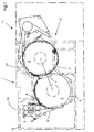
- Fig. 1 is a side view of a folder according to the invention with two interacting paper leading cylinders, e.g. B. a folding knife cylinder and one Jaw cylinder.
- two interacting paper leading cylinders e.g. B. a folding knife cylinder and one Jaw cylinder.
- the folder 1 shown in Fig. 1 comprises two side frame assemblies 13 and one Web inlet section 14, through which a web enters the folder 1.
- a few interacting cutting cylinder 2 cut the incoming material web into individual Signatures recorded by a first and a second band arrangement 3, 4.
- the signatures are then from a first folding cylinder 5, z. B. one Folding knife cylinder, recorded with a surface 6.
- Within a schematically represented Product transfer area 7 the signatures cut from the material web a second paper leading cylinder 8, e.g. B. pass a jaw cylinder.
- the cross-folded products e.g. B. newspapers, are from the surface 9 of the second Paper leading cylinder 8 passed to belt assemblies 10 that the signatures on Pass on further processing equipment or stacking equipment.
- a substantially horizontal product delivery path can also be provided, the however, no further detail in the embodiment of the present invention shown in FIG. 1 is shown.
- the folder 1, which is shown only schematically in FIG. 1, can be used as a pin-less needle Folder can be formed in which the signatures preferably by along the Signature arrangements arranged band arrangements are detected.
- the The present invention can also be used in folders, the puncture needles for Capture the signatures on paper-bearing cylinders 5, 8 include.
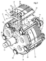
- Fig. 2 shows a perspective view of a paper leading invention Cylinder, which is designed here, for example, as a folding jaw cylinder.
- the paper-carrying cylinder 8 has a plurality of on its peripheral surface Folding flaps, each with a fixed flap element 17 and a movable one Include flap element 18.
- Folding flaps By moving one on the peripheral surface of one first paper leading cylinder 5 (Fig. 1) arranged folding knife incoming signatures folded transversely and inserted into the jaws.
- the folding blades of the first paper act when performing a transverse folding process Cylinder 5 together with the jaws of the jaw cylinder 8.
- the upper layer 20 of the surface section 19 consists of a resistant, relatively dense, yet flexible material with high wear resistance and exhibits Tape guide grooves in which tapes can run. These grooves are from each other spaced across the width of the top layer 20 and serve as side Guides for band arrangements interacting with the surface sections 19 for signature delivery.
- Hard plastic layer 25 which serves as a tape drive and tape running surface.
- This Hard plastic layer 25 corresponds to the contour of the paper-guiding cylinder 8 bent.
- a compressible layer 24 arranged and z. B. glued to the bottom of the hard plastic layer 25 or on others Way attached to this.
- the compressible layer 24 is also corresponding to FIG Shape of the hard plastic layer 25 curved in an arc.
- the compressible layer 24 can e.g. B. from a foam with open cells or a rubber component or similar material exist, which can assume a compressed state and after after all forces have been removed, it returns to its original form.
- the thickness of the compressible layer 24 can be between 20 mm and 25 mm or 30 mm, however, preferably be approximately 22 mm.
- an attachment base 26 is arranged, which consists of either metal or hard plastic.
- the Bottom 31 of the top base 26 is preferably flat and as long as that of the Side walls of the cylinder arranged fastening surfaces 29.
- the top base 26 further includes a curved according to the curvature of the compressible layer 24 Surface 32. Both the hard plastic layer 25 and the upper layer 20 have Tape guide grooves.
- the entire arrangement of the upper layer 20, the hard plastic layer 25, the compressible layer 24 and the top base 26 is by means of fastening means, for. B. Bolts or screws 22 attached to the mounting surfaces 29.
- Each of the layers of the Surface portions 19 of the cylinder have openings 21 at their end portions which e.g. B. for removing the sections 19, easy accessibility of the sections 19th enable.
- the surface sections 19 are more resistant against material stress and due to a paper jam on the Circumferential surface 9 acting forces. Because the layer arrangement is compressible made possible by approximately 20 mm, the surface sections 19 in the event of a paper jam slowly deformed. If the associated paper leading cylinder 5, e.g. B. a Folding knife cylinder, also has surface sections 19 according to the invention, so a total compressibility of about 40 mm on both cylinder surfaces 6, 9 reached. In the event of a paper jam, the 6.9 move on the respective cylinder surface jammed signatures the respective surface section 19 on the center line of the Cylinder 5, 8 too, so that space is created for the jammed signatures.
- the associated paper leading cylinder 5 e.g. B. a Folding knife cylinder
- the movable flap element 18 by means of a here unspecified eccentric cooperating eccentric roller 16 is actuated.
- the arranged on a lever member eccentric roller 16 rotates in bearings 28 in the respective Side wall mounted shaft 27 about its axis, so that an adjusting movement of the movable Flap element 18 is triggered in the direction of the stationary flap element 17.
- a jaw cylinder 8 shown, the five activatable arranged spaced along the circumferential surface 9 Includes jaws.
- the surface sections 19 according to the invention can advantageously in pointless needles are used, in which the transfer of signatures done by tape systems, the use of retractable pin needles unnecessary do.
- the upper layer 20 according to the invention of the surface sections 19 points to lateral guidance of transport systems, e.g. B. tapes, as in pinpoint needles Folders are used, grooves on.
- folders can also be used retractable product capture elements such as B. pin needles with compressible surface sections 19 according to the invention.
Landscapes
- Folding Of Thin Sheet-Like Materials, Special Discharging Devices, And Others (AREA)
- Rotary Presses (AREA)
- Supply, Installation And Extraction Of Printed Sheets Or Plates (AREA)
Abstract
Die vorliegende Erfindung betrifft einen Papier führenden Zylinder in einem einer
Rotationsdruckmaschine, z. B. einer Zeitungsdruckmaschine, zugeordneten Falzapparat.
Eine Vielzahl von Oberflächenabschnitten (19) ist um die Umfangsoberfläche des Zylinders
(8) befestigt. Jeder der Oberflächenabschnitte (19) weist eine Schichtstruktur auf, die eine
komprimierbare Schicht (24) umfasst. Die Oberflächenabschnitte (19) sind vorzugsweise
abnehmbar und bevorzugt an an den Seitenwänden des Zylinders (8) angeordneten
Befestigungsflächen (29) befestigt.

Description
Die vorliegende Erfindung betrifft einen Papier führenden Zylinder, insbesondere einen Papier führenden Zylinder in einem Falzapparat.The present invention relates to a paper-carrying cylinder, in particular one Paper leading cylinder in a folder.
Die US Patentanmeldung mit der Nummer US 09/124,907 betrifft eine Vorrichtung zur Veränderung des Durchmessers eines Zylinders. Die Vorrichtung umfasst eine abnehmbar auf einer Zylinderoberfläche befestigte Mantelkomponente. Auf dieser einfach zu wechselnden Mantelkomponente, die eine Basisplatte umfasst, ist ein elastisches Material vorgesehen, durch das eine Komprimierbarkeit der Oberfläche erreicht wird. Die in dieser Schrift beschriebene Lösung ermöglicht eine schnelle Anpassung des Zylinderdurchmessers an die Erfordernisse.The US patent application with the number US 09 / 124,907 relates to a device for Change the diameter of a cylinder. The device includes a removable shell component attached to a cylinder surface. On this just too changing sheath component, which comprises a base plate, is an elastic material provided by which a compressibility of the surface is achieved. The one in this Solution described in writing enables a quick adjustment of the cylinder diameter to the requirements.
Aufgrund der sehr dünnen Oberflächenbeschichtung ist die mit dieser Lösung erreichbare Kompensationswirkung jedoch sehr begrenzt.Due to the very thin surface coating, the one that can be achieved with this solution However, the compensation effect is very limited.
Die US 5,039,076 betrifft einen Falzapparat. Bei einem Falzapparat mit mindestens zwei mit zusammenwirkenden Falzelementen in Form von Falzmessern und Falzklappern versehenen Falzzylindern, bei dem Produkte sehr unterschiedlicher Dicke verarbeitet werden sollen, lässt sich eine zuverlässige Produktionsweise dadurch erreichen, dass mindestens ein Falzzylinder Umfangsabschnitte aufweist, die in radialer Richtung verstellbar sind. Zum radialen Verstellen der Umfangsabschnitte sind Stellelemente vorgesehen. Die Umfangsabschnitte sind um eine zur Zylinderachse parallele Achse schwenkbar im Bereich des vorderen Endes der Umfangsabschnitte angeordnet, wobei das hintere Ende der Umfangsabschnitte mittels der Stellelemente in radialer Richtung verstellbar ist.US 5,039,076 relates to a folder. With a folder with at least two with interacting folding elements in the form of folding knives and folding jaws Folding cylinders, in which products of very different thicknesses are to be processed, a reliable production method can be achieved by at least one Folding cylinder has circumferential sections that are adjustable in the radial direction. To the Radial adjustment of the peripheral sections are provided. The Circumferential sections are pivotable in the region about an axis parallel to the cylinder axis of the front end of the peripheral portions, the rear end of the Circumferential sections can be adjusted in the radial direction by means of the adjusting elements.
Die US 5,000,433 betrifft ebenfalls einen Falzapparat, insbesondere einen verstellbaren Falzapparat für Rollen-Tiefdruckmaschinen mit einem Sammelzylinder. Der Sammelzylinder kann von Sammelproduktion auf Nichtsammelproduction umgestellt werden und umfasst Halteelemente (vorzugsweise in Form von Greifern) sowie Falzmesser mit vorzugsweise als Tastrollen ausgebildeten Betätigung selementen, die durch eine Steuerkurve steuerbar sind, deren vorzugsweise als eine Vertiefung ausgebildeter aktiver Steuerbereich mittels einer mit auf einem zur zugehörigen Steuerkurve koaxialen, antreibbaren Nockenträger aufgenommenen Abdecknocken versehenen Abdeckeinrichtung wahlweise freigebbar oder abdeckbar ist. Um ein hohes Maß an Anpassungsfähigkeit an verschiedene Arten von Sammelproduktionen zu erreichen, sind die Abdecknocken der Abdeckeinrichtung derart auf einem Nockenträger aufgenommen, dass sie radial verstellbar sind.US 5,000,433 also relates to a folder, in particular an adjustable one Folder for rotogravure printing machines with a collecting cylinder. The collecting cylinder can be switched from collective production to non-collective production and includes Holding elements (preferably in the form of grippers) and folding knives with preferably as Selector rollers trained actuation elements that can be controlled by a control curve, whose preferably formed as an indentation active control area by means of a on a drivable cam carrier coaxial to the associated control cam Recorded cam provided cover device either releasable or can be covered. To be highly adaptable to different types of To achieve collective productions, the cover cams of the cover device are such recorded on a cam carrier that they are radially adjustable.
In diesem technischen Bereich, insbesondere bei der Produktion von Zeitungen mit einer großen Anzahl Seiten, z. B. mit 48 oder 64 Seiten, nimmt die Behebung von Papierstaus sehr viel Zeit in Anspruch. Ein bekanntes Mittel zur Erhöhung der Flexibilität und Verformbarkeit der Oberfläche eines Papier führenden Zylinders, z. B. eines Falzklappen- oder Falzmesserzylinders, besteht darin, voneinander beabstandete, einzelne Streifen auf die Oberfläche eines Papier führenden Zylinders aufzubringen. Durch diese aus einem auf Kunststoff aufgebrachten Urethanschaum mit geschlossenen Zellen gefertigten Streifen wird jedoch nur ein geringes Maß an Verformbarkeit der Oberfläche eines Papier führenden Zylinders, z. B. eines Falzklappenzylinders, erreicht. Bei der Produktion von Zeitungen mit 48 oder sogar mehr Seiten ist ein höheres Maß an Verformbarkeit der Oberfläche eines Papier führenden Zylinders nötig.In this technical field, especially in the production of newspapers with a large number of pages, e.g. B. with 48 or 64 pages, eliminates paper jams very time consuming. A well known means of increasing flexibility and Deformability of the surface of a paper-carrying cylinder, e.g. B. a jaw or Folding knife cylinder, consists of spaced individual strips on the Apply the surface of a paper-guiding cylinder. Through this out of one Plastic applied urethane foam with closed cell strips however, only a small degree of deformability is leading to the surface of a paper Cylinders, e.g. B. a jaw cylinder reached. In the production of newspapers with 48 or even more pages is a higher degree of deformability of the surface of one Paper leading cylinder necessary.
Demgemäß ist es eine Aufgabe der vorliegenden Erfindung, einen Papier führenden Zylinder mit einem höheren Maß an Verformbarkeit der Oberfläche zu schaffen, der bei an den Zylindern auftretenden Papierstaus weniger anfällig für Beschädigungen ist und bei dem Wartungs- und Reparaturarbeiten weniger Zeit in Anspruch nehmen.Accordingly, it is an object of the present invention to provide a paper carrying cylinder to create with a higher degree of deformability of the surface, which at the Cylinder jams are less prone to damage and at the same time Maintenance and repair work take less time.
Diese Aufgabe wird durch eine Vorrichtung mit den Merkmalen gemäß Anspruch 1 gelöst.This object is achieved by a device with the features according to claim 1.
Ein erfindungsgemäßer Papier führender Zylinder umfasst eine Vielzahl von um seine Umfangsoberfläche befestigten Oberflächenabschnitten, die eine Schichtstruktur mit einer an einer weiteren Schicht haftenden komprimierbaren Schicht umfassen und abnehmbar an Befestigungsabschnitten des Zylinders befestigt sind.A paper-guiding cylinder according to the invention comprises a multiplicity of around its Circumferential surface attached surface sections that have a layer structure with a comprise another layer of adhesive compressible layer and removable Fastening sections of the cylinder are attached.
Die Vorteile der erfindungsgemäßen Lösung liegen darin, dass zum Wechseln der Oberflächenabschnitte im Falle eines Papierstaus nur sehr wenig Zeit benötigt wird. The advantages of the solution according to the invention are that for changing the Surface sections in the event of a paper jam take very little time.
Aufgrund der Komprimierbarkeit der Oberflächenabschnitte des Zylinders werden Teile der Zylinderoberfläche zur Mitte des Papier führenden Zylinders hin verformt, so dass in dem Zylinderspalt zwischen zwei zusammenwirkenden Zylindern ein größerer Zwischenraum entsteht. Dadurch werden Beschädigungen an den Bauteilen der komplexen Papier führenden Zylinder vermieden, so dass nach einem Papierstau der Produktionslauf schneller wieder aufgenommen werden kann. Die abnehmbar an dem Zylinderkörper befestigten elastischen Oberflächenabschnitte sind in höherem Maße als bekannte Vorrichtungen verformbar, so dass ohne Anpassung des Zylinderspalts Produkte von größerer Dicke, z. B. Zeitungen mit hoher Seitenanzahl, bearbeitet werden können.Due to the compressibility of the surface sections of the cylinder, parts of the Cylinder surface deformed towards the center of the paper-carrying cylinder, so that in the Cylinder gap between two interacting cylinders a larger gap arises. This will damage the components of the complex paper leading cylinders avoided, so that after a paper jam the production run faster can be resumed. The detachably attached to the cylinder body elastic surface sections are to a greater extent than known devices deformable, so that products of greater thickness, e.g. B. Newspapers with a high number of pages, can be edited.
Gemäß einer vorteilhaften Ausführungsform der vorliegenden Erfindung weisen die Oberflächenabschnitte eine Schichtstruktur auf, die eine stabilisierende Hartplastikschicht umfasst. Durch diese stabilisierende Schicht wird die Steifigkeit der Schichtstruktur des gesamten Oberflächenabschnitts erhöht. Die Schichtstruktur umfasst ferner vorzugsweise eine obere Schicht, in der Bandführungsnuten zur Führung eines Transportbands gebildet sind. Darüber hinaus ist unter der Schichtstruktur der Oberflächenabschnitte zwischen den Oberflächenabschnitten und den an den Seitenwänden des Papier führenden Zylinders angeordneten Befestigungsabschnitten vorzugsweise eine Aufsatzbasis vorgesehen. Bei dem Papier führenden Zylinder kann es sich z. B. um einen Sammelzylinder, einen Falzmesserzylinder oder einen Falzklappenzylinder handeln.According to an advantageous embodiment of the present invention, the Surface sections a layer structure on which a stabilizing hard plastic layer includes. This stabilizing layer increases the rigidity of the layer structure of the entire surface section increased. The layer structure preferably further comprises an upper layer formed in the belt guide grooves for guiding a conveyor belt are. In addition, under the layer structure of the surface sections between the Surface sections and the cylinder on the side walls of the paper arranged attachment sections preferably provided an attachment base. In which Paper leading cylinder can be z. B. a collecting cylinder, a Trade folding knife cylinder or a folding jaw cylinder.
Die stabilisierende Hartplastikschicht, die einen Teil der Schichtstruktur bilden kann, wirkt als ein Bandantrieb, da die obere Schicht der Schichtstruktur voneinander beabstandete Bandführungsnuten aufweist, deren Boden von der stabilisierenden Hartplastikschicht gebildet wird. Die die Bandführungsnuten aufweisende obere Schicht kann z. B. aus einem harten Urethan oder aus einem Gummimaterial bestehen. Die Dicke der oberen Schicht der Schichtstruktur beträgt vorzugsweise zwischen 3 mm und 8 mm, insbesondere vorzugsweise 6 mm.The stabilizing hard plastic layer, which can form part of the layer structure, works as a belt drive because the top layer of the layer structure was spaced apart Has tape guide grooves, the bottom of the stabilizing hard plastic layer is formed. The upper layer having the tape guide grooves may e.g. B. from one hard urethane or a rubber material. The thickness of the top layer of the Layer structure is preferably between 3 mm and 8 mm, in particular preferably 6 mm.
Die komprimierbare Schicht ist vorzugsweise an der gebogenen Unterseite der stabilisierenden Hartplastikschicht befestigt und kann z. B. aus einem mit der Hartplastikschicht verklebten aufgeschäumten Material bestehen. Die Dicke der komprimierbaren Schicht beträgt vorzugsweise zwischen 15 mm und 25 mm, insbesondere vorzugsweise 22 mm. Unterhalb der komprimierbaren Schicht aus einem aufgeschäumten, komprimierbaren Material ist vorzugsweise eine aus Hartplastik oder Metall gefertigte Aufsatzbasis angeordnet, die eine flache Unterseite umfasst, mittels derer die Aufsatzbasis an den an den Seitenrahmen des Papier führenden Zylinders angeordneten Befestigungsflächen befestigt ist, und die eine gebogene Oberseite umfasst, deren Form der mit der stabilisierenden Hartplastikschicht verbundenen, gebogenen komprimierbaren Schicht der Schichtatruktur entspricht. Die Oberflächenabschnitte mit Schichtstruktur sind mit abnehmbaren Befestigungselementen wie z. B. Schrauben oder Bolzen an den an den Seitenwänden des Zylinders angeordneten Befestigungsflächen befestigt. Wie bereits erwähnt, ist zwischen den Befestigungsflächen des Zylinders und den Oberflächenabschnitten eine Aufsatzbasis angeordnet.The compressible layer is preferably on the curved underside of the stabilizing hard plastic layer attached and can e.g. B. from one with the Hard plastic layer of glued foamed material. The thickness of the compressible layer is preferably between 15 mm and 25 mm, in particular preferably 22 mm. Below the compressible layer of a foamed, Compressible material is preferably one made of hard plastic or metal Attachment base arranged, which comprises a flat underside, by means of which the attachment base arranged on the cylinders leading to the side frames of the paper Fastening surfaces is attached, and which includes a curved top, the shape of which curved compressible bonded to the stabilizing hard plastic layer Layer corresponds to the layer structure. The surface sections are layered with removable fasteners such. B. screws or bolts on the Side walls of the cylinder arranged mounting surfaces attached. As before mentioned, is between the mounting surfaces of the cylinder and the Surface sections arranged an attachment base.
Bei den Papier führenden Zylinders des Falzapparats handelt es sich beispielsweise um einen Falzmesserzylinder, an dessen Umfangsoberfläche eine Vielzahl von Falzmessern angeordnet ist. Die Papier führenden Zylinder können auch als Falzklappenzylinder ausgebildet sein, wie es im Folgenden beispielhaft näher erläutert wird, oder es kann sich um Sammelzylinder handeln.The paper-leading cylinders of the folder are, for example, one Folding knife cylinder with a large number of folding knives on the circumferential surface is arranged. The paper-guiding cylinders can also be used as folding jaw cylinders be formed, as will be explained in more detail below by way of example, or it can be Trade collecting cylinders.
Die erfindungsgemäße Lösung kann in vorteilhafter Weise in einem einer Rotationsdruckmaschine, z. B. einer Rollenrotationsdruckmaschine für die Produktion von Zeitungen, nachgeordneten Falzapparat, insbesondere auch in einem punkturnadellosen Falzapparat, eingesetzt werden.The solution according to the invention can advantageously in one Rotary printing machine, e.g. B. a web-fed rotary printing press for the production of Newspapers, subordinate folder, especially also in a single-needle Folder can be used.
Weitere Merkmale der Erfindung ergeben sich aus den Unteransprüchen.Further features of the invention emerge from the subclaims.
Weitere Vorteile und vorteilhafte Ausführungsformen sind Gegenstand der nachfolgend dargestellten Figuren sowie deren Beschreibungen.Further advantages and advantageous embodiments are the subject of the following shown figures and their descriptions.
Es zeigen:
- Fig. 1
- eine Seitenansicht eines Falzapparats mit zwei beispielhaft als ein Falzmesserzylinder und ein Falzklappenzylinder ausgebildeten, zusammenwirkenden Papier führenden Zylindern,
- Fig. 2
- eine perspektivische Darstellung eines beispielhaft als ein Falzklappenzylinder ausgebildeten Papier führenden Zylinders eines Falzapparats, an dessen Umfangsoberfläche eine Vielzahl von Falzklappen angeordnet ist.
- Fig. 1
- 2 shows a side view of a folding apparatus with two interacting paper-guiding cylinders designed as a folding knife cylinder and a folding jaw cylinder,
- Fig. 2
- a perspective view of an exemplary designed as a folding jaw cylinder paper cylinder of a folder, on the peripheral surface of which a plurality of folding jaws is arranged.
Fig. 1 ist eine Seitenansicht eines erfindungsgemäßen Falzapparats mit zwei zusammenwirkenden Papier führenden Zylindern, z. B. einem Falzmesserzylinder und einem Falzklappenzylinder.Fig. 1 is a side view of a folder according to the invention with two interacting paper leading cylinders, e.g. B. a folding knife cylinder and one Jaw cylinder.
Der in Fig. 1 gezeigte Falzapparat 1 umfasst zwei Seitenrahmenanordnungen 13 und einen
Bahneinlaufabschnitt 14, durch den eine Bahn in den Falzapparat 1 einläuft. Ein Paar
zusammenwirkender Schneidezylinder 2 schneiden die einlaufende Materialbahn in einzelne
Signaturen, die von einer ersten und zweiten Bandanordnung 3,4 aufgenommen werden.
Die Signaturen werden dann von einem ersten Falzzylinder 5, z. B. einem
Falzmesserzylinder, mit einer Oberfläche 6 erfasst. Innerhalb eines schematisch dargestellten
Produktübergabebereichs 7 werden die von der Materialbahn geschnittenen Signaturen an
einen zweiten Papier führenden Zylinder 8, z. B. einen Falzklappenzylinder, übergeben. Bei
der Übergabe von dem ersten Falzzylinder 5 an den zweiten Falzzylinder 8 werden die
Signaturen quer gefalzt und dabei von Falzmessern in die auf der Umfangsoberfläche 9 des
zweiten Papier führenden Zylinders 8 voneinander beabstandet angeordneten Falzklappen
18 geschoben, die in Fig. 2 näher gezeigt sind.The folder 1 shown in Fig. 1 comprises two
Die quer gefalzten Produkte, z. B. Zeitungen, werden von der Oberfläche 9 des zweiten
Papier führenden Zylinders 8 an Bandanordnungen 10 übergeben, die die Signaturen an
Weiterverarbeitungseinrichtungen oder Stapeleinrichtungen weitergeben.The cross-folded products, e.g. B. newspapers, are from the
Anstelle des gezeigten, im Wesentlichen vertikal verlaufenden Auslegebandsystems 11 kann
auch eine im Wesentlichen horizontal verlaufende Produktauslegebahn vorgesehen sein, die
jedoch in der in Fig. 1 gezeigten Ausführungsform der vorliegenden Erfindung nicht näher
gezeigt ist.Instead of the essentially vertically extending
Der in Fig. 1 nur schematisch dargestellt Falzapparat 1 kann als ein punkturnadelloser
Falzapparat ausgebildet sein, in dem die Signaturen vorzugsweise durch entlang der
Signaturenführungsbahn angeordnete Bandanordnungen erfasst werden. Alternativ kann die
vorliegende Erfindung auch in Falzapparaten eingesetzt werden, die Punkturnadeln zum
Erfassen der Signaturen auf Papier führenden Zylindern 5, 8 umfassen.The folder 1, which is shown only schematically in FIG. 1, can be used as a pin-less needle
Folder can be formed in which the signatures preferably by along the
Signature arrangements arranged band arrangements are detected. Alternatively, the
The present invention can also be used in folders, the puncture needles for
Capture the signatures on paper-bearing
Fig. 2 zeigt eine perspektivische Darstellung eines erfindungsgemäßen Papier führenden Zylinders, der hier beispielsweise als ein Falzldappenzylinder ausgebildet ist.Fig. 2 shows a perspective view of a paper leading invention Cylinder, which is designed here, for example, as a folding jaw cylinder.
Der Papier führende Zylinder 8 weist an seiner Umfangsoberfläche eine Vielzahl von
Falzklappen auf, die jeweils ein ortsfestes Klappenelement 17 und ein bewegbares
Klappenelement 18 umfassen. Durch die Bewegung eines auf der Umfangsoberfläche eines
ersten Papier führenden Zylinders 5 (Fig. 1) angeordneten Falzmessers werden die
einlaufenden Signaturen quer gefalzt und in die Falzklappen eingeschoben. Zur
Durchführung eines Querfalzvorgangs wirken die Falzmesser des ersten Papier führenden
Zylinders 5 mit den Falzklappen des Falzklappenzylinders 8 zusammen.The paper-carrying
Entlang der Umfangsoberfläche des Falzklappenzylinders 8 sind Oberflächenabschnitte 19
angeordnet, die mehrere Schichten umfassen.Along the circumferential surface of the
Die obere Schicht 20 des Oberflächenabschnitts 19 besteht aus einem widerstandsfähigen,
relativ dichten, aber dennoch flexiblen Material mit hoher Abnutzungsfestigkeit und weist
Bandführungsnuten auf, in denen Bänder laufen können. Diese Nuten sind voneinander
beabstandet über die Breite der oberen Schicht 20 angeordnet und dienen als seitliche
Führungen für mit den Oberflächenabschnitten 19 zusammenwirkende Bandanordnungen
zur Signaturenübergabe.The
Unterhalb der oberen, mit Kerben versehenen Schicht 20 befindet sich eine
Hartplastikschicht 25, die als Bandantriebs- und Bandlauffläche dient. Diese
Hartplastikschicht 25 ist der Kontur des Papier führenden Zylinders 8 entsprechend
gebogen. Auf der Unterseite der Hartplastikschicht 25 ist eine komprimierbare Schicht 24
angeordnet und z. B. mit der Unterseite der Hartplastikschicht 25 verklebt oder auf andere
Weise an dieser befestigt. Die komprimierbare Schicht 24 ist ebenfalls entsprechend der
Form der Hartplastikschicht 25 bogenförmig gekrümmt. Die komprimierbare Schicht 24
kann z. B. aus einem Schaum mit offenen Zellen oder einem Gummibestandteit oder einem
ähnliches Material bestehen, das einen komprimierten Zustand annehmen kann und nach
dem Entfernen aller Kräfte wieder in seine ursprüngliche Form zurückkehrt.Below the upper, notched
Die Dicke der komprimierbaren Schicht 24 kann zwischen 20 mm und 25 mm oder 30 mm,
vorzugsweise jedoch ca. 22 mm betragen. Unterhalb der komprimierbaren Schicht 24 ist
eine Aufsatzbasis 26 angeordnet, die entweder aus Metall oder Hartplastik besteht. Die
Unterseite 31 der Aufsatzbasis 26 ist vorzugsweise flach und so lang wie die an den
Seitenwänden der Zylinder angeordneten Befestigungsflächen 29. Die Aufsatzbasis 26
umfasst ferner eine entsprechend der Biegung der komprimierbaren Schicht 24 gebogene
Oberfläche 32. Sowohl die Hartplastikschicht 25 als auch die obere Schicht 20 weisen
Bandführungsnuten auf.The thickness of the
Die gesamte Anordnung aus der oberen Schicht 20, der Hartplastikschicht 25, der
komprimierbaren Schicht 24 und der Aufsatzbasis 26 ist mittels Befestigungsmitteln, z. B.
Bolzen oder Schrauben 22, an den Befestigungsflächen 29 befestigt. Jede der Schichten der
Oberflächenabschnitte 19 des Zylinders weist an ihren Endabschnitten Öffnungen 21 auf, die
z. B. zum Abnehmen der Abschnitte 19 eine leichte Zugänglichkeit der Abschnitte 19
ermöglichen.The entire arrangement of the
Aufgrund ihrer Schichtstruktur sind die Oberflächenabschnitte 19 widerstandsfähiger
gegenüber Materialbeanspruchungen und den aufgrund eines Papierstaus auf die
Umfangsoberfläche 9 wirkenden Kräften. Da die Schichtanordnung eine Komprimierbarkeit
um etwa 20 mm ermöglicht, werden die Oberflächenabschnitte 19 bei einem Papierstau
langsam verformt. Wenn der zugeordnete Papier führende Zylinder 5, z. B. ein
Falzmesserzylinder, ebenfalls erfindungagemäße Oberflächenabschnitte 19 aufweist, so wird
an beiden Zylinderoberflächen 6, 9 insgesamt eine Komprimierbarkeit um ca. 40 mm
erreicht. Bei einem Papierstau bewegen die an der jeweiligen Zylinderoberfläche 6,9
gestauten Signaturen den jeweiligen Oberflächenabschnitt 19 auf die Mittellinie des
Zylinders 5, 8 zu, so dass Raum für die gestauten Signaturen geschaffen wird.Due to their layer structure, the
Aufgrund der Anordnung der Befestigungselemente an den Endabschnitten der
Oberflächenabschnitte 19 wird die zum Wechseln abgenutzter Elemente benötigte
Wartungszeit reduziert. Da sich die Oberflächenabschnitte 19 um etwa 20 mm in Richtung
auf die Zylinderachse zu komprimieren lassen, wird die Gefahr von Beschädigungen an den
Zylinderbauteilen und damit auch die Stillstandszeit der Maschine bedeutend reduziert. Das
Wiederanlaufen der Produktion nach einem Papierstau und ein Wechseln abgenutzter
Oberflächenabschnitte kann viel schneller erfolgen als bei Zylindern der bekannten
Bauweise. Die gesamte Aufsatzanordnung mit der oberen Schicht 20, der Hartplastikschicht
25, der komprimierbaren Schicht 24 und der Aufsatzbasis 26 kann bei Bedarf schnell und
einfach ausgewechselt werden.Due to the arrangement of the fasteners at the end portions of the
Aufgrund der Verformbarkeit der Oberflächen 6, 9 der mit Oberflächenabschnitten 19
versehenen Papier führenden Zylinder 5, 8 können Beschädigungen der an den
Seitenwänden der Zylinder 5, 8 angeordneten Zapfen 15 vermieden werden. Dadurch sind
auch die Lagerungen der Zapfen 15 vor Beschädigungen durch Papierstaus geschützt.Due to the deformability of the
Zu erwähnen ist ferner, dass das bewegbare Klappenelement 18 mittels einer mit einem hier
nicht näher bezeichneten Exzenter zusammenwirkenden Exzenterrolle 16 betätigt wird. Die
an einem Hebelglied angeordnete Exzenterrolle 16 dreht eine in Lagern 28 in der jeweiligen
Seitenwand gelagerte Welle 27 um ihre Achse, so dass eine Stellbewegung des bewegbaren
Klappenelements 18 in die Richtung des ortsfesten Klappenelements 17 ausgelöst wird. In
der in Fig. 2 gezeigten Anordnung der vorliegenden Erfindung ist ein Falzklappenzylinder 8
gezeigt, der fünf entlang der Umfangsoberfläche 9 beabstandet angeordnete, aktivierbare
Falzklappen umfasst.It should also be mentioned that the
Die erfindungsgemäßen Oberflächenabschnitte 19 können in vorteilhafter Weise in
punkturnadellosen Falzapparaten eingesetzt werden, in denen die Übergabe der Signaturen
durch Bandsysteme erfolgt, die den Einsatz von zurückziehbaren Punkturnadeln unnötig
machen. Die erfindungsgemäße obere Schicht 20 der Oberflächenabschnitte 19 weist zur
seitlichen Führung von Transportsystemen, z. B. Bändern, wie sie in punkturnadellosen
Falzapparaten eingesetzt werden, Nuten auf. Es können jedoch auch Falzapparate mit
zurückziehbaren Produkterfassungselementen wie z. B. Punkturnadeln mit den
erfindungsgemäßen komprimierbaren Oberflächenabschnitten 19 ausgestattet werden. In der
Produktion von Zeitungen mit beispielsweise bis zu 48, 64 oder 96 Seiten kann auf diese
Weise eine Verformbarkeit der zusammenwirkenden, Produkt führenden Zylinder 5, 8 in
dem Zylinderspalt um etwa 40 mm erreicht werden, so dass die Zylinder vor
Beschädigungen geschützt sind und die Stillstandszeiten der Maschine zu Wartungsarbeiten
reduziert werden. The
- 11
- FalzapparatFolder
- 22nd
- SchneidezylinderCutting cylinder
- 33rd
- erste Bandanordnungfirst band arrangement
- 44th
- zweite Bandanordnungsecond band arrangement
- 55
- erster Falzzylinderfirst folding cylinder
- 66
- Oberflächesurface
- 77
- ProduktübergabebereichProduct transfer area
- 88th
- zweiter Falzzylindersecond folding cylinder
- 99
- Oberflächesurface
- 1010th
- BandanordnungBand arrangement
- 1111
- BandauslagesystemBelt delivery system
- 1212th
- ProduktauslageProduct display
- 1313
- SeitenrahmenSide frame
- 1414
- BahneinlaufabschnittWeb entry section
- 1515
- ZapfenCones
- 1616
- ExzenterrolleEccentric role
- 1717th
- ortsfestes Klappenelementfixed flap element
- 1818th
- bewegbares Klappenelementmovable flap element
- 1919th
- OberflächenabschnittSurface section
- 2020th
- obere Schichtupper layer
- 2121
- Öffnungopening
- 2222
- BefestigungsmittelFasteners
- 2323
- gebogene Unterseitecurved bottom
- 2424th
- komprimierbare Schichtcompressible layer
- 2525th
- HartplastikschichtHard plastic layer
- 2626
- AufsatzbasisEssay base
- 2727
- StellwelleControl shaft
- 2828
- Lagerungstorage
- 2929
- Befestigungsfläche Mounting surface
- 3030th
- hohler Innenraumhollow interior
- 3131
- flache Unterseiteflat bottom
- 3232
- gebogene Oberseitecurved top
Claims (20)
gekennzeichnet durch
eine Vielzahl von um die Umfangsoberfläche (6, 9) eines Zylinders (5, 8) befestigten Oberflächenabschnitten (19), die mehrere Schichten (20, 24, 25, 26) umfassen, wobei eine der Schichten eine komprimierbare Schicht (24) ist.Cylinder carrying paper, in particular in a folder (1),
marked by
a plurality of surface portions (19) attached around the peripheral surface (6, 9) of a cylinder (5, 8) and comprising a plurality of layers (20, 24, 25, 26), one of the layers being a compressible layer (24).
dadurch gekennzeichnet,
dass die befestigten Oberflächenabschnitte (19) abnehmbar an Befestigungsabschnitten (29) des Zylinders (8) befestigt sind.Paper-guiding cylinder according to claim 1,
characterized,
that the attached surface portions (19) are removably attached to attachment portions (29) of the cylinder (8).
dadurch gekennzeichnet,
dass die Schichtstruktur der Oberflächenabschnitte (19) eine stabilisierende Hartplastikschicht (25) umfasst.Paper-guiding cylinder according to claim 1 or 2,
characterized,
that the layer structure of the surface sections (19) comprises a stabilizing hard plastic layer (25).
dadurch gekennzeichnet,
dass die Schichtstruktur der Oberflächenabschnitte (19) eine obere Schicht (20) mit Bandführungsnuten umfasst.Paper-guiding cylinder according to one of the preceding claims,
characterized,
that the layer structure of the surface sections (19) comprises an upper layer (20) with tape guide grooves.
dadurch gekennzeichnet,
dass zwischen dem Oberflächenabschnitt (19) und dem Befestigungsabschnitt (29) eine Aufsatzbasis (26) befestigt ist.Paper-guiding cylinder according to claim 2,
characterized,
that an attachment base (26) is fastened between the surface section (19) and the fastening section (29).
dadurch gekennzeichnet,
dass die stabilisierende Hartplastikschicht (25) eine harte Oberfläche aufweist, die als Bandantrieb dient. Paper guiding cylinder according to claim 3,
characterized,
that the stabilizing hard plastic layer (25) has a hard surface that serves as a belt drive.
dadurch gekennzeichnet,
dass die obere Schicht (20) aus einem harten Urethan besteht.Paper guiding cylinder according to claim 3,
characterized,
that the upper layer (20) consists of a hard urethane.
dadurch gekennzeichnet,
dass die obere Schicht (20) aus einem Gummimaterial besteht.Paper-guiding cylinder according to claim 4,
characterized,
that the upper layer (20) consists of a rubber material.
dadurch gekennzeichnet,
dass die obere Schicht (20) eine Dicke von etwa 3 bis 8 mm aufweist.Paper guiding cylinder according to claim 3,
characterized,
that the upper layer (20) has a thickness of about 3 to 8 mm.
dadurch gekennzeichnet,
dass die komprimierbare Schicht (24) aus einem komprimierbaren, aufgeschäumten Material besteht, das mit der Hartplastikschicht (25) verklebt ist.Paper-guiding cylinder according to one of the preceding claims,
characterized,
that the compressible layer (24) consists of a compressible, foamed material which is glued to the hard plastic layer (25).
dadurch gekennzeichnet,
dass die komprimierbare Schicht (24) eine Dicke von 15 mm bis 25 mm aufweist.Paper-guiding cylinder according to one of the preceding claims,
characterized,
that the compressible layer (24) has a thickness of 15 mm to 25 mm.
dadurch gekennzeichnet,
dass die Aufsatzbasis (26) aus Hartplastik oder Metall ist.Paper-guiding cylinder according to claim 5,
characterized,
that the attachment base (26) is made of hard plastic or metal.
dadurch gekennzeichnet,
dass die obere Schicht (20) zur Führung von Bändern Bandführungsnuten aufweist.Paper guiding cylinder according to claim 3,
characterized,
that the upper layer (20) for guiding tapes has tape guide grooves.
dadurch gekennzeichnet,
dass die Oberflächenabschnitte (19) durch abnehmbare Befestigungsmittel (22) an den Befestigungsflächen (29) des Zylinders (5, 8) befestigt sind.Paper-guiding cylinder according to one of the preceding claims,
characterized,
that the surface sections (19) are fastened to the fastening surfaces (29) of the cylinder (5, 8) by removable fastening means (22).
dadurch gekennzeichnet,
dass der Zylinder als ein Falzmesserzylinder (5) ausgebildet ist.Paper-guiding cylinder according to one of the preceding claims,
characterized,
that the cylinder is designed as a folding knife cylinder (5).
dadurch gekennzeichnet,
dass der Zylinder als ein Falzklappenzylinder (8) ausgebildet ist.Paper-guiding cylinder according to one of claims 1 to 14,
characterized,
that the cylinder is designed as a folding jaw cylinder (8).
dadurch gekennzeichnet,
dass der Zylinder als ein Sammelzylinder ausgebildet ist.Paper-guiding cylinder according to one of claims 1 to 14,
characterized,
that the cylinder is designed as a collecting cylinder.
einer Vielzahl von um die Umfangsoberfläche (6, 9) eines Zylinders (5, 8) befestigten Oberflächenabschnitten (19), die mehrere Schichten (20, 24, 25, 26) umfassen, wobei eine der Schichten eine komprimierbare Schicht (24) ist.Folder with
a plurality of surface portions (19) attached around the circumferential surface (6, 9) of a cylinder (5, 8) and comprising a plurality of layers (20, 24, 25, 26), one of the layers being a compressible layer (24).
dadurch gekennzeichnet,
dass die befestigten Oberflächenabschnitte (19) abnehmbar an Befestigungsabschnitten (29) des Zylinders (8) befestigt sind.Folding apparatus according to claim 18,
characterized,
that the attached surface portions (19) are removably attached to attachment portions (29) of the cylinder (8).
die eine Vielzahl von um die Umfangsoberfläche (9) eines Zylinders (5, 8) befestigten Oberflächenabschnitten (19) umfassen, die mehrere Schichten (20, 24, 25, 26) aufweisen, wobei eine der Schichten eine komprimierbare Schicht (24) ist.Rotary printing machine with paper-guiding cylinders,
which comprise a plurality of surface sections (19) fastened around the peripheral surface (9) of a cylinder (5, 8) and having a plurality of layers (20, 24, 25, 26), one of the layers being a compressible layer (24).
Applications Claiming Priority (2)
| Application Number | Priority Date | Filing Date | Title |
|---|---|---|---|
| US09/315,331 US6250622B1 (en) | 1999-05-20 | 1999-05-20 | Cylinder assembly for a folding apparatus of a rotary printing press |
| US315331 | 1999-05-20 |
Publications (3)
| Publication Number | Publication Date |
|---|---|
| EP1053965A2 true EP1053965A2 (en) | 2000-11-22 |
| EP1053965A3 EP1053965A3 (en) | 2002-12-18 |
| EP1053965B1 EP1053965B1 (en) | 2004-02-11 |
Family
ID=23223922
Family Applications (1)
| Application Number | Title | Priority Date | Filing Date |
|---|---|---|---|
| EP00109008A Expired - Lifetime EP1053965B1 (en) | 1999-05-20 | 2000-04-26 | Cylinder arrangement for a folding apparatus of a rotary printing machine |
Country Status (5)
| Country | Link |
|---|---|
| US (1) | US6250622B1 (en) |
| EP (1) | EP1053965B1 (en) |
| JP (1) | JP4638573B2 (en) |
| AT (1) | ATE259331T1 (en) |
| DE (2) | DE10020316A1 (en) |
Cited By (3)
| Publication number | Priority date | Publication date | Assignee | Title |
|---|---|---|---|---|
| WO2003057487A1 (en) * | 2002-01-07 | 2003-07-17 | Alan John Fawcett | A die plate for a foil stamping machine |
| DE102007019132A1 (en) * | 2007-04-20 | 2008-10-30 | Manroland Ag | Fold flap cylinder for printing press folding apparatus has base body shaped to T-shaped cross section in one sector |
| EP3363634A1 (en) * | 2017-02-21 | 2018-08-22 | manroland web systems GmbH | Insert for a folding cylinder and method for producing the same |
Families Citing this family (9)
| Publication number | Priority date | Publication date | Assignee | Title |
|---|---|---|---|---|
| US7338425B1 (en) * | 2000-01-12 | 2008-03-04 | Goss International Americas, Inc. | Variable length cutting device |
| US6547232B2 (en) * | 2000-12-01 | 2003-04-15 | Heidelberger Druckmaschinen Ag | Device and method for switching between collect and straight modes on a folder |
| US6843763B2 (en) * | 2001-12-13 | 2005-01-18 | Goss International Americas, Inc. | Folder cylinder with support plate |
| DE102004020304B4 (en) * | 2004-04-26 | 2007-11-29 | Koenig & Bauer Aktiengesellschaft | Cylinder for processing flat material |
| DE102004020303B4 (en) * | 2004-04-26 | 2007-12-27 | Koenig & Bauer Aktiengesellschaft | Cylinder for processing flat material |
| US7896795B2 (en) * | 2005-10-25 | 2011-03-01 | Goss International Americas, Inc. | Folder with signature support |
| DE102007026386B4 (en) * | 2007-06-06 | 2012-09-27 | Shw Casting Technologies Gmbh | Roll body with profile channels for a tempering fluid |
| DE102008035108A1 (en) * | 2008-07-28 | 2010-02-04 | Heidelberger Druckmaschinen Ag | Bogenfalzmaschine |
| DE102013102729A1 (en) * | 2013-03-18 | 2014-09-18 | Manroland Web Systems Gmbh | Folding device of a printing press and method for operating the folding device |
Family Cites Families (13)
| Publication number | Priority date | Publication date | Assignee | Title |
|---|---|---|---|---|
| US1821713A (en) * | 1930-01-17 | 1931-09-01 | Scott Isabella | Paper handling device |
| US2229487A (en) * | 1940-02-28 | 1941-01-21 | C B Cottreil & Sons Company | Sheet collecting and folding mechanism for printing presses |
| US2335431A (en) * | 1942-10-16 | 1943-11-30 | Cottrell C B & Sons Co | Sheet collecting and folding mechanism for printing presses |
| US3180007A (en) * | 1963-12-13 | 1965-04-27 | Eruest W Gartz | Quick change roller coating plate |
| US4349185A (en) * | 1980-07-21 | 1982-09-14 | Paper Converting Machine Company | Folding apparatus |
| JP2538925B2 (en) * | 1987-06-24 | 1996-10-02 | 三菱重工業株式会社 | Diameter adjustment device for folding cylinders in rotary press |
| DE3828372C2 (en) | 1988-08-20 | 1995-12-21 | Frankenthal Ag Albert | Folder |
| DE3831182A1 (en) * | 1988-09-13 | 1990-03-15 | Wifag Maschf | COLLECTING CYLINDERS FOR DOT FOLDING MACHINES FROM ROTATIONAL PRINTING MACHINES |
| DE3906975A1 (en) * | 1989-03-04 | 1990-09-06 | Frankenthal Ag Albert | FOLDING APPARATUS |
| DE3932931A1 (en) * | 1989-10-03 | 1991-04-11 | Roland Man Druckmasch | FOLDING VALVE CYLINDER FOR A FOLDING APPARATUS |
| JP2513226Y2 (en) * | 1990-07-26 | 1996-10-02 | 三菱重工業株式会社 | Folding cylinder diameter adjusting device |
| DE4234307A1 (en) * | 1992-10-12 | 1994-04-14 | Heidelberger Druckmasch Ag | Device for trouble-free product conveyance in folders |
| DE4344622A1 (en) * | 1993-12-24 | 1995-06-29 | Koenig & Bauer Ag | Wheel folder for a rotary printing machine |
-
1999
- 1999-05-20 US US09/315,331 patent/US6250622B1/en not_active Expired - Lifetime
-
2000
- 2000-04-26 DE DE10020316A patent/DE10020316A1/en not_active Withdrawn
- 2000-04-26 AT AT00109008T patent/ATE259331T1/en not_active IP Right Cessation
- 2000-04-26 DE DE50005237T patent/DE50005237D1/en not_active Expired - Lifetime
- 2000-04-26 EP EP00109008A patent/EP1053965B1/en not_active Expired - Lifetime
- 2000-05-22 JP JP2000149517A patent/JP4638573B2/en not_active Expired - Fee Related
Cited By (5)
| Publication number | Priority date | Publication date | Assignee | Title |
|---|---|---|---|---|
| WO2003057487A1 (en) * | 2002-01-07 | 2003-07-17 | Alan John Fawcett | A die plate for a foil stamping machine |
| AU2003201389B2 (en) * | 2002-01-07 | 2006-11-16 | Tms Technologies Inc. | A die plate for a foil stamping machine |
| DE102007019132A1 (en) * | 2007-04-20 | 2008-10-30 | Manroland Ag | Fold flap cylinder for printing press folding apparatus has base body shaped to T-shaped cross section in one sector |
| DE102007019132B4 (en) * | 2007-04-20 | 2011-07-07 | manroland AG, 63075 | Insert for a jaw cylinder |
| EP3363634A1 (en) * | 2017-02-21 | 2018-08-22 | manroland web systems GmbH | Insert for a folding cylinder and method for producing the same |
Also Published As
| Publication number | Publication date |
|---|---|
| DE50005237D1 (en) | 2004-03-18 |
| JP4638573B2 (en) | 2011-02-23 |
| US6250622B1 (en) | 2001-06-26 |
| JP2000351194A (en) | 2000-12-19 |
| EP1053965B1 (en) | 2004-02-11 |
| ATE259331T1 (en) | 2004-02-15 |
| EP1053965A3 (en) | 2002-12-18 |
| DE10020316A1 (en) | 2000-12-14 |
Similar Documents
| Publication | Publication Date | Title |
|---|---|---|
| EP0408912B1 (en) | Method and device for production of paperstacks | |
| EP1053965B1 (en) | Cylinder arrangement for a folding apparatus of a rotary printing machine | |
| DE4340858C2 (en) | cylinder | |
| CH693985A5 (en) | Vorrichtung und Verfahren zum Schneiden einer Materialbahn, insbesondere in einer Rotationsdruckmaschine. | |
| EP0468254B1 (en) | Transverse cutter for printed web | |
| DE19708213A1 (en) | Method and device for product guidance in a fold formation area of a folding apparatus | |
| EP1097892B1 (en) | Device for and method of cutting and deviating signatures | |
| DE19519373A1 (en) | Folder | |
| DE10102220A1 (en) | Pick-up appliance for web of flat material in folding appliance comprises transfer and cutting cylinders, pick-up elements, grooved bars and knives | |
| EP1120374A2 (en) | Switchable gripper for products in a folding apparatus | |
| DE10254332A1 (en) | folding cylinder | |
| DE19931002A1 (en) | Cylinder diameter adjustment has casing component with aluminum or steel plate and top elastic material, clamp and fastening | |
| DE10235897A1 (en) | Tape transport system for printed products has supporting arm which includes two side rails, such that first pulley is supported rotatably between side rails | |
| EP1110894B1 (en) | Method and device for folding sheets of material | |
| EP0462372B1 (en) | Device for cylinder rotary machine | |
| EP1108672A2 (en) | Method and device for linear folding | |
| WO1988000919A1 (en) | Device for collecting and depositing folded printed items in an overlapping manner on a conveyer belt | |
| DE10114064A1 (en) | Delivery device for flat sheets in rotary printing machines has control body associated with rotating transfer element and controlling underpressure and pressure impulse to take up and release sheets of different thickness | |
| DE19519372C2 (en) | Modular conveyor belt mechanism | |
| DE19754151A9 (en) | Folding apparatus for printers | |
| EP1201591A1 (en) | Guide for flat signatures in folding devices | |
| DE19754151A1 (en) | Folding apparatus for printers | |
| EP0516068A1 (en) | Device for stacking and forming batches of folded or unfolded sections of paper, cellulose, fibrous webs or the like | |
| DE102012209581B4 (en) | Sheet processing machine with a feed table | |
| DE19542695A1 (en) | Folder with a product holder |
Legal Events
| Date | Code | Title | Description |
|---|---|---|---|
| PUAI | Public reference made under article 153(3) epc to a published international application that has entered the european phase |
Free format text: ORIGINAL CODE: 0009012 |
|
| AK | Designated contracting states |
Kind code of ref document: A2 Designated state(s): AT BE CH CY DE DK ES FI FR GB GR IE IT LI LU MC NL PT SE |
|
| AX | Request for extension of the european patent |
Free format text: AL;LT;LV;MK;RO;SI |
|
| PUAL | Search report despatched |
Free format text: ORIGINAL CODE: 0009013 |
|
| AK | Designated contracting states |
Kind code of ref document: A3 Designated state(s): AT BE CH CY DE DK ES FI FR GB GR IE IT LI LU MC NL PT SE |
|
| AX | Request for extension of the european patent |
Free format text: AL;LT;LV;MK;RO;SI |
|
| 17P | Request for examination filed |
Effective date: 20021108 |
|
| 17Q | First examination report despatched |
Effective date: 20030331 |
|
| GRAP | Despatch of communication of intention to grant a patent |
Free format text: ORIGINAL CODE: EPIDOSNIGR1 |
|
| AKX | Designation fees paid |
Designated state(s): AT BE CH CY DE DK ES FI FR GB GR IE IT LI LU MC NL PT SE |
|
| GRAS | Grant fee paid |
Free format text: ORIGINAL CODE: EPIDOSNIGR3 |
|
| GRAA | (expected) grant |
Free format text: ORIGINAL CODE: 0009210 |
|
| AK | Designated contracting states |
Kind code of ref document: B1 Designated state(s): AT BE CH CY DE DK ES FI FR GB GR IE IT LI LU MC NL PT SE |
|
| PG25 | Lapsed in a contracting state [announced via postgrant information from national office to epo] |
Ref country code: IE Free format text: LAPSE BECAUSE OF FAILURE TO SUBMIT A TRANSLATION OF THE DESCRIPTION OR TO PAY THE FEE WITHIN THE PRESCRIBED TIME-LIMIT Effective date: 20040211 Ref country code: NL Free format text: LAPSE BECAUSE OF FAILURE TO SUBMIT A TRANSLATION OF THE DESCRIPTION OR TO PAY THE FEE WITHIN THE PRESCRIBED TIME-LIMIT Effective date: 20040211 Ref country code: FI Free format text: LAPSE BECAUSE OF FAILURE TO SUBMIT A TRANSLATION OF THE DESCRIPTION OR TO PAY THE FEE WITHIN THE PRESCRIBED TIME-LIMIT Effective date: 20040211 Ref country code: CY Free format text: LAPSE BECAUSE OF FAILURE TO SUBMIT A TRANSLATION OF THE DESCRIPTION OR TO PAY THE FEE WITHIN THE PRESCRIBED TIME-LIMIT Effective date: 20040211 |
|
| REG | Reference to a national code |
Ref country code: GB Ref legal event code: FG4D Free format text: NOT ENGLISH |
|
| REG | Reference to a national code |
Ref country code: CH Ref legal event code: EP |
|
| REG | Reference to a national code |
Ref country code: IE Ref legal event code: FG4D Free format text: GERMAN |
|
| REF | Corresponds to: |
Ref document number: 50005237 Country of ref document: DE Date of ref document: 20040318 Kind code of ref document: P |
|
| GBT | Gb: translation of ep patent filed (gb section 77(6)(a)/1977) |
Effective date: 20040318 |
|
| PG25 | Lapsed in a contracting state [announced via postgrant information from national office to epo] |
Ref country code: LU Free format text: LAPSE BECAUSE OF NON-PAYMENT OF DUE FEES Effective date: 20040426 Ref country code: AT Free format text: LAPSE BECAUSE OF NON-PAYMENT OF DUE FEES Effective date: 20040426 |
|
| PG25 | Lapsed in a contracting state [announced via postgrant information from national office to epo] |
Ref country code: BE Free format text: LAPSE BECAUSE OF NON-PAYMENT OF DUE FEES Effective date: 20040430 Ref country code: MC Free format text: LAPSE BECAUSE OF NON-PAYMENT OF DUE FEES Effective date: 20040430 |
|
| PG25 | Lapsed in a contracting state [announced via postgrant information from national office to epo] |
Ref country code: DK Free format text: LAPSE BECAUSE OF FAILURE TO SUBMIT A TRANSLATION OF THE DESCRIPTION OR TO PAY THE FEE WITHIN THE PRESCRIBED TIME-LIMIT Effective date: 20040511 Ref country code: GR Free format text: LAPSE BECAUSE OF FAILURE TO SUBMIT A TRANSLATION OF THE DESCRIPTION OR TO PAY THE FEE WITHIN THE PRESCRIBED TIME-LIMIT Effective date: 20040511 Ref country code: SE Free format text: LAPSE BECAUSE OF FAILURE TO SUBMIT A TRANSLATION OF THE DESCRIPTION OR TO PAY THE FEE WITHIN THE PRESCRIBED TIME-LIMIT Effective date: 20040511 |
|
| PG25 | Lapsed in a contracting state [announced via postgrant information from national office to epo] |
Ref country code: ES Free format text: LAPSE BECAUSE OF FAILURE TO SUBMIT A TRANSLATION OF THE DESCRIPTION OR TO PAY THE FEE WITHIN THE PRESCRIBED TIME-LIMIT Effective date: 20040522 |
|
| NLV1 | Nl: lapsed or annulled due to failure to fulfill the requirements of art. 29p and 29m of the patents act | ||
| REG | Reference to a national code |
Ref country code: IE Ref legal event code: FD4D |
|
| BERE | Be: lapsed |
Owner name: HEIDELBERGER DRUCKMASCHINEN A.G. Effective date: 20040430 |
|
| REG | Reference to a national code |
Ref country code: GB Ref legal event code: 732E |
|
| ET | Fr: translation filed | ||
| RAP2 | Party data changed (patent owner data changed or rights of a patent transferred) |
Owner name: GOSS INTERNATIONAL AMERICAS, INC. |
|
| PLBE | No opposition filed within time limit |
Free format text: ORIGINAL CODE: 0009261 |
|
| STAA | Information on the status of an ep patent application or granted ep patent |
Free format text: STATUS: NO OPPOSITION FILED WITHIN TIME LIMIT |
|
| 26N | No opposition filed |
Effective date: 20041112 |
|
| REG | Reference to a national code |
Ref country code: CH Ref legal event code: NV Representative=s name: KIRKER & CIE SA |
|
| REG | Reference to a national code |
Ref country code: FR Ref legal event code: TP |
|
| PG25 | Lapsed in a contracting state [announced via postgrant information from national office to epo] |
Ref country code: PT Free format text: LAPSE BECAUSE OF NON-PAYMENT OF DUE FEES Effective date: 20040711 |
|
| PGFP | Annual fee paid to national office [announced via postgrant information from national office to epo] |
Ref country code: IT Payment date: 20070518 Year of fee payment: 8 |
|
| PG25 | Lapsed in a contracting state [announced via postgrant information from national office to epo] |
Ref country code: IT Free format text: LAPSE BECAUSE OF NON-PAYMENT OF DUE FEES Effective date: 20080426 |
|
| PGFP | Annual fee paid to national office [announced via postgrant information from national office to epo] |
Ref country code: DE Payment date: 20110427 Year of fee payment: 12 Ref country code: FR Payment date: 20110504 Year of fee payment: 12 Ref country code: CH Payment date: 20110425 Year of fee payment: 12 |
|
| PGFP | Annual fee paid to national office [announced via postgrant information from national office to epo] |
Ref country code: GB Payment date: 20110426 Year of fee payment: 12 |
|
| REG | Reference to a national code |
Ref country code: CH Ref legal event code: PL |
|
| GBPC | Gb: european patent ceased through non-payment of renewal fee |
Effective date: 20120426 |
|
| REG | Reference to a national code |
Ref country code: FR Ref legal event code: ST Effective date: 20121228 |
|
| PG25 | Lapsed in a contracting state [announced via postgrant information from national office to epo] |
Ref country code: LI Free format text: LAPSE BECAUSE OF NON-PAYMENT OF DUE FEES Effective date: 20120430 Ref country code: GB Free format text: LAPSE BECAUSE OF NON-PAYMENT OF DUE FEES Effective date: 20120426 Ref country code: CH Free format text: LAPSE BECAUSE OF NON-PAYMENT OF DUE FEES Effective date: 20120430 |
|
| REG | Reference to a national code |
Ref country code: DE Ref legal event code: R119 Ref document number: 50005237 Country of ref document: DE Effective date: 20121101 |
|
| PG25 | Lapsed in a contracting state [announced via postgrant information from national office to epo] |
Ref country code: FR Free format text: LAPSE BECAUSE OF NON-PAYMENT OF DUE FEES Effective date: 20120430 |
|
| PG25 | Lapsed in a contracting state [announced via postgrant information from national office to epo] |
Ref country code: DE Free format text: LAPSE BECAUSE OF NON-PAYMENT OF DUE FEES Effective date: 20121101 |