EP1053966A2 - Löschbare Haltevorrichtung für den Bremsträger in Fadenliefervorrichtungen von Textilmaschinen - Google Patents
Löschbare Haltevorrichtung für den Bremsträger in Fadenliefervorrichtungen von Textilmaschinen Download PDFInfo
- Publication number
- EP1053966A2 EP1053966A2 EP00109103A EP00109103A EP1053966A2 EP 1053966 A2 EP1053966 A2 EP 1053966A2 EP 00109103 A EP00109103 A EP 00109103A EP 00109103 A EP00109103 A EP 00109103A EP 1053966 A2 EP1053966 A2 EP 1053966A2
- Authority
- EP
- European Patent Office
- Prior art keywords
- brake
- slider
- drum
- brake support
- magnets
- Prior art date
- Legal status (The legal status is an assumption and is not a legal conclusion. Google has not performed a legal analysis and makes no representation as to the accuracy of the status listed.)
- Granted
Links
Images


Classifications
-
- D—TEXTILES; PAPER
- D03—WEAVING
- D03D—WOVEN FABRICS; METHODS OF WEAVING; LOOMS
- D03D47/00—Looms in which bulk supply of weft does not pass through shed, e.g. shuttleless looms, gripper shuttle looms, dummy shuttle looms
- D03D47/34—Handling the weft between bulk storage and weft-inserting means
- D03D47/36—Measuring and cutting the weft
- D03D47/361—Drum-type weft feeding devices
- D03D47/364—Yarn braking means acting on the drum
-
- D—TEXTILES; PAPER
- D03—WEAVING
- D03D—WOVEN FABRICS; METHODS OF WEAVING; LOOMS
- D03D47/00—Looms in which bulk supply of weft does not pass through shed, e.g. shuttleless looms, gripper shuttle looms, dummy shuttle looms
- D03D47/34—Handling the weft between bulk storage and weft-inserting means
- D03D47/36—Measuring and cutting the weft
- D03D47/361—Drum-type weft feeding devices
- D03D47/364—Yarn braking means acting on the drum
- D03D47/366—Conical
Definitions
- the present invention relates to a releasable retainer for the brake support of weft feeders for textile machines, particularly weaving looms.
- weft feeders are devices which comprise a fixed drum on which a hollow rotating arm winds, like a fishing reel, a plurality of turns of thread which constitute a weft reserve and which, when requested by the loom, unwind from the drum in order to feed said loom under the control of a brake which is meant to generate a mechanical tension on the thread being unwound.
- the brake is constituted by braking means such as a frustum-shaped element made of polymeric material which is appropriately stiffened and optionally provided with high-resistance material, or a ring of bristles or elastically flexible metallic laminas.
- braking means such as a frustum-shaped element made of polymeric material which is appropriately stiffened and optionally provided with high-resistance material, or a ring of bristles or elastically flexible metallic laminas.
- Said braking means are usually suspended elastically and are supported by an appropriately provided brake support, in front of the drum of the feeder, in order to elastically engage the thread that slides on the portion that blends the cylindrical surface with the front surface of said drum.
- the brake support is constituted by a rigid ring which is in turn supported concentrically to the drum of the feeder by a slider which can slide on guides which run parallel to the axis of the drum.
- Said slider is controlled by a precision adjustment system of the screw-and-nut type, provided with an actuation knob, which allows to move the slider and the supporting ring rigidly coupled thereto in a direction which is parallel to the axis of said drum in order to vary the elastic force ⁇ the so-called static tension ⁇ with which the braking means act on the weft thread.
- pneumatic quick-release systems which comprise a double-acting fluid-actuated jack which is adapted to move the support rigidly together with the corresponding supporting slider or the entire adjustment system from an active position, in which the brake is in contact with the drum, to a disengagement position, in which the brake is spaced from the drum for maintenance, and vice versa.
- pneumatic systems of this type disclosed in published European patent applications No. 446.447, 657.379, and 659.918, are complicated and expensive and require fitting the feeder with a pneumatic circuit; therefore they can be used conveniently only in specific and limited cases, particularly when the feeder is already provided with a similar circuit which is used mainly for pneumatic threading.
- Quick-release systems are also known in which the entire adjustment system can move rigidly with the slider of the brake support and is subjected to the action of a spring which tends to move the slider and the support into a disengagement position, in which the braking means is spaced from the drum of the weft feeder.
- the spring is contrasted by a stop element which keeps it normally loaded and keeps the braking means in the active position in contact with the drum; disengagement of the stop element produces the snap movement of the slider and of the brake support into the disengagement position of the braking means.
- the aim of the present invention is to eliminate these and other drawbacks of conventional systems for retaining and disengaging the brake support, and within the scope of this aim it has the particular object of providing a releasable retainer for the support which has a simple structure and is highly reliable in operation and very easy to maneuver both during disengagement and during the return of said support to the active position.
- Another object of the present invention is to provide a device for disengaging the brake support which does not affect the ease of operation of the static tension adjustment knob and is also suitable to maintain the setting of the static tension, so that after the intervention has been performed the support is returned to the active position and the brake requires no correction of the setting.
- the invention is based on the innovative concept of subjecting the entire screw-and-nut adjustment system associated with the movable slider that supports the brake support to the action of at least one pair of mutually opposite permanent magnets, whose identical poles are juxtaposed so as to repel each other; and of contrasting the mutual repulsion of said magnets with a stop element, actuated by a disengagement lever, which engages a corresponding retention groove of the pivot of the adjustment screw in order to keep said magnets and the brake normally in the active position, the magnets being in mutual contact and the stop element being in contact with the drum of the feeder.
- the displacement of the brake after the releasing action on the retainer is advantageously carried out by means of two successive disengagement movements or strokes for displacing said brake from its active braking position into a disengagement position suitable for allowing intervention on the brake, i.e. a first movement or stroke caused by the repulsion action of the mutually opposite magnets and a subsequent hand-operated movement or stroke.
- the active position of the brake is restored through two distinct return movements or strokes by applying to the adjustment screw actuation knob an axial pressure which is adapted to make the pivot of the screw slide in the opposite direction.
- the repulsion effect of the opposite magnets is not effective owing to the gap between the opposite magnets exceeding the threshold of the magnetic effect.
- the second return movement or stroke occurs instead in contrast with the repulsion of said mutually opposite magnets, until the stop element is returned into alignment with the retention groove of said pivot.
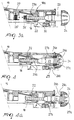
- the reference numeral 10 generally designates a conventional weft feeder which comprises a fixed base 11 and a fixed drum 12 on which a hollow rotating arm 13, rigidly coupled to a driving shaft 14 which is also hollow, winds like a fishing reel a plurality of turns of thread F that constitutes a weft reserve RT.
- a brake generally designated by the reference numeral 15, which is meant to produce adequate mechanical tension on the thread.
- Said brake comprises a continuous frustum-shaped body which is suspended elastically, by means of a radial set of springs 16, from a brake support 17 and is pushed against the portion 12b where the cylindrical surface 12a of the drum blends with the front surface 12c in order to elastically engage, for braking, the thread F that passes, in its unwinding motion, over said blending surface in order to reach an output thread guiding ring G.
- the brake support 17 is constituted by a rigid ring which is rigidly coupled to a slider 18 which is supported, so that it can move in a straight line, by a fixed arm 19 of the feeder which runs parallel to the axis of the drum 12.
- the slider 18 is provided with two bushes (not shown) which slidingly engage corresponding cylindrical guides (not shown) which are supported by an arm 19.
- a female threaded element 22 is rigidly coupled to the slider 18, and an adjustment screw engages therein; said screw is constituted by the threaded end portion 23a of a pivot 23 which is provided with an adjustment knob 24 by means of which it is possible to turn the adjustment screw without any axial movement thereof and produce by virtue of the non-rotating female threaded element 22 axial precision movements of the slider 18 and of the brake support 17.
- These movements indicated by an indicator 18a of the slider which moves along a graduated scale of the arm 19, allow to adjust the elastic pressure, known as static tension, with which the brake 15 acts on the drum and therefore the degree of braking action applied by said brake to the thread F.
- a disengagement system which allows to move the brake support ring 17 toward the outside of the feeder 10 without actuating the knob 24 and accordingly to move the brake 15 away from the drum 12 in order to move it into the disengagement position of Figures 3a-4a, in which the braking means is accessible both for cleaning and for replacement and/or maintenance.
- the pivot 23 of the adjustment system is supported by a cooperating fixed bush 25 so that the pivot 23 can always rotate about its axis and can also be axially moved when a stop element 28 is released.
- the fixed bush 25 is rigidly coupled to the arm 19 and the axial movement of the pivot 23 is obtained by the rotation of pivot 23 about its axis and the screw thread engagement with female threads of the fixed bush 25.
- Said pivot 23 has, at its end, a permanent magnet 26', preferably made of a material with high magnetic hysteresis, such as samarium-cobalt and neodymium, having a preset N-S magnetic polarity as shown in the figure.
- a similar magnet 26'' is arranged co-axially to the magnet 26', lies opposite thereto, and is accommodated in a hollow seat 27 of the arm 19.
- the N-S polarity of the magnet 26'' is orientated in reverse with respect to the polarity of the magnet 26', and therefore the two magnets have juxtaposed identical poles, so as to repel each other.
- the stop element 28 is constituted by the upper portion of an annular bracket 28a which is rigidly coupled to an actuation lever 30, which is pivoted to the arm 19 at an end 30a and is subjected to the action of a spring 31 which normally keeps the stop element 28 engaged in the retention groove 29 and accordingly keeps the brake 15 in the active position of Figures 3 and 4.
- the stop element 28 disengages from the groove 29 and the entire adjustment system accordingly performs a translatory motion and, actuated by the repulsion force of the magnets 26'-26'', moves into a position which is sufficient to make the knob 24 protrude in front of the arm 19.
- the knob can thus be gripped in order to manually complete the movement of the brake 15 into the disengagement position.
- Figures 4 and 4a differs only in that it comprises two or more magnets 26a accommodated in respective hollow seats 27a provided on the abutment of the mushroom-shaped head of the knob 24 and, correspondingly, two or more mutually opposite magnets 26b accommodated in corresponding hollow seats 27b provided on the bush 25 which is rigidly coupled to the arm 19. Also in this case, the polarities of the magnets are opposite, so that their identical poles are juxtaposed.
Landscapes
- Engineering & Computer Science (AREA)
- Textile Engineering (AREA)
- Looms (AREA)
- Replacing, Conveying, And Pick-Finding For Filamentary Materials (AREA)
- Unwinding Of Filamentary Materials (AREA)
Applications Claiming Priority (3)
| Application Number | Priority Date | Filing Date | Title |
|---|---|---|---|
| ITTO990081 | 1999-05-11 | ||
| IT1999TO000081 IT247942Y1 (it) | 1999-05-11 | 1999-05-11 | Dispositivo di ritegno a sgancio del supporto portafreno diapparecchi alimentatori di trama per macchine tessili. |
| ITTO990081U | 1999-05-11 |
Publications (3)
| Publication Number | Publication Date |
|---|---|
| EP1053966A2 true EP1053966A2 (de) | 2000-11-22 |
| EP1053966A3 EP1053966A3 (de) | 2001-11-21 |
| EP1053966B1 EP1053966B1 (de) | 2003-08-20 |
Family
ID=11417428
Family Applications (1)
| Application Number | Title | Priority Date | Filing Date |
|---|---|---|---|
| EP20000109103 Expired - Lifetime EP1053966B1 (de) | 1999-05-11 | 2000-05-04 | Lösbare Haltevorrichtung für den Bremsträger in Fadenliefervorrichtungen von Textilmaschinen |
Country Status (3)
| Country | Link |
|---|---|
| EP (1) | EP1053966B1 (de) |
| DE (1) | DE60004603T2 (de) |
| IT (1) | IT247942Y1 (de) |
Cited By (1)
| Publication number | Priority date | Publication date | Assignee | Title |
|---|---|---|---|---|
| EP1334941A1 (de) * | 2002-02-01 | 2003-08-13 | L.G.L. Electronics S.p.A. | Haltevorrichtung für den Bremsträger in Fadenliefervorrichtungen |
Family Cites Families (4)
| Publication number | Priority date | Publication date | Assignee | Title |
|---|---|---|---|---|
| US4242955A (en) * | 1978-03-13 | 1981-01-06 | North Atlantic Industries, Inc. | Magnetically actuated equipment |
| DE4022562A1 (de) * | 1990-07-16 | 1992-01-23 | Schlafhorst & Co W | Lagerung fuer einen offenend-spinnrotor |
| US5622040A (en) * | 1994-12-21 | 1997-04-22 | W. Schlafhorst Ag & Co. | Bearing for an open-end spinning rotor |
| RU2129089C1 (ru) * | 1995-07-24 | 1999-04-20 | Иро Аб | Устройство для подачи нити |
-
1999
- 1999-05-11 IT IT1999TO000081 patent/IT247942Y1/it active
-
2000
- 2000-05-04 EP EP20000109103 patent/EP1053966B1/de not_active Expired - Lifetime
- 2000-05-04 DE DE2000604603 patent/DE60004603T2/de not_active Expired - Fee Related
Cited By (2)
| Publication number | Priority date | Publication date | Assignee | Title |
|---|---|---|---|---|
| EP1334941A1 (de) * | 2002-02-01 | 2003-08-13 | L.G.L. Electronics S.p.A. | Haltevorrichtung für den Bremsträger in Fadenliefervorrichtungen |
| CN100408738C (zh) * | 2002-02-01 | 2008-08-06 | 爱吉尔电子股份公司 | 用于保持纬纱进给装置中的制动器保持件支座的装置 |
Also Published As
| Publication number | Publication date |
|---|---|
| ITTO990081U1 (it) | 2000-11-11 |
| DE60004603D1 (de) | 2003-09-25 |
| ITTO990081V0 (it) | 1999-05-11 |
| IT247942Y1 (it) | 2002-09-16 |
| DE60004603T2 (de) | 2004-06-24 |
| EP1053966B1 (de) | 2003-08-20 |
| EP1053966A3 (de) | 2001-11-21 |
Similar Documents
| Publication | Publication Date | Title |
|---|---|---|
| DE69514069T2 (de) | Modulierte positive Fadenbremse für Schussfadenliefervorrichtungen | |
| CN103946138B (zh) | 具有磁制动器的储存类型的纱线供给器 | |
| KR100371989B1 (ko) | 제어가능한출력브레이크및발사체또는그리퍼직조기 | |
| EP0536088B1 (de) | Modulierte Fadenbremse für eine Schussfadenliefervorrichtung | |
| EP0622485B1 (de) | Vorrichtung zum modulierten Bremsen des Fadens für Schussfadenliefervorrichtungen | |
| EP2924156B1 (de) | Garnbremsvorrichtung für Speicherfournisseur | |
| EP2169099A1 (de) | Negativer Garnzuführer mit Schussfadenbremsvorrichtung | |
| EP0652312B1 (de) | Positiv modulierte Fadenbremse für Schussfadenliefervorrichtungen | |
| EP2065496B1 (de) | Fadenzuführungsvorrichtung und Fadenbremse | |
| EP1053966B1 (de) | Lösbare Haltevorrichtung für den Bremsträger in Fadenliefervorrichtungen von Textilmaschinen | |
| EP0826619B1 (de) | Schnellauslösehalterung für das Bremslager von Schussfadenspeichern für Textilmaschinen | |
| EP0698135B1 (de) | Schussfadenliefervorrichtung mit vorrichtung zum trennen von wendungen für schnelllaufende luftdüsenwebmaschinen | |
| EP3608460B1 (de) | Schussfadenbremsvorrichtung für speicherfadenzuführvorrichtungen | |
| EP1334941B1 (de) | Haltevorrichtung für den Bremsträger in Fadenliefervorrichtungen | |
| EP0699790B1 (de) | Fadenfesthalteorgan für Schussfadenspeicher für Luftwebmaschinen | |
| EP1624098B1 (de) | Eine Schussfadenliefervorrichtung für Webmaschinen mit einer selbsteinstellenden Fadenbremsvorrichtung | |
| EP0754645A1 (de) | Elektropneumatische Vorrichtung zum automatischen Einfädeln eines Schussfadenzubringers und Schussfadenzubringer der diese Vorrichtung enthält | |
| EP0581745B1 (de) | Verbesserung von Schussfadenliefervorrichtungen für pneumatische Webmaschinen | |
| EP0884263B1 (de) | Selbstregulierende modulierte Fadenbremse für eine Schussfadenliefervorrichtung | |
| EP0867390B1 (de) | Selbsteinstellende Fadenbremsvorrichtungen für Fadenliefervorrichtungen | |
| EP3392384B1 (de) | Schussfadenbremsvorrichtung für speicherfadenzuführvorrichtungen und zuführvorrichtung mit solch einer schussfadenbremsvorrichtung | |
| EP1262436B1 (de) | Schnell-Befestigungsvorrichtung für Bremseinheiten von Schussfadenliefervorrichtungen für Webmaschinen | |
| CN111051586A (zh) | 用于纬线给送器装置的线制动装置 | |
| CS198014B1 (cs) | Univerzální upínací trn pro upínání kuželových i válcových cívek na textilních strojích, zejména soukacích a dopřádacích strojích a cívečnicich váeeh druhů |
Legal Events
| Date | Code | Title | Description |
|---|---|---|---|
| PUAI | Public reference made under article 153(3) epc to a published international application that has entered the european phase |
Free format text: ORIGINAL CODE: 0009012 |
|
| AK | Designated contracting states |
Kind code of ref document: A2 Designated state(s): AT BE CH CY DE DK ES FI FR GB GR IE IT LI LU MC NL PT SE Kind code of ref document: A2 Designated state(s): BE CH DE IT LI SE |
|
| AX | Request for extension of the european patent |
Free format text: AL;LT;LV;MK;RO;SI |
|
| PUAL | Search report despatched |
Free format text: ORIGINAL CODE: 0009013 |
|
| AK | Designated contracting states |
Kind code of ref document: A3 Designated state(s): AT BE CH CY DE DK ES FI FR GB GR IE IT LI LU MC NL PT SE |
|
| AX | Request for extension of the european patent |
Free format text: AL;LT;LV;MK;RO;SI |
|
| 17P | Request for examination filed |
Effective date: 20020307 |
|
| AKX | Designation fees paid |
Free format text: BE CH DE IT LI SE |
|
| GRAH | Despatch of communication of intention to grant a patent |
Free format text: ORIGINAL CODE: EPIDOS IGRA |
|
| GRAH | Despatch of communication of intention to grant a patent |
Free format text: ORIGINAL CODE: EPIDOS IGRA |
|
| GRAA | (expected) grant |
Free format text: ORIGINAL CODE: 0009210 |
|
| REG | Reference to a national code |
Ref country code: SE Ref legal event code: TRGR |
|
| AK | Designated contracting states |
Designated state(s): BE CH DE IT LI SE |
|
| REG | Reference to a national code |
Ref country code: CH Ref legal event code: EP |
|
| REF | Corresponds to: |
Ref document number: 60004603 Country of ref document: DE Date of ref document: 20030925 Kind code of ref document: P |
|
| REG | Reference to a national code |
Ref country code: CH Ref legal event code: NV Representative=s name: RITSCHER & PARTNER AG PATENTANWAELTE |
|
| PLBE | No opposition filed within time limit |
Free format text: ORIGINAL CODE: 0009261 |
|
| STAA | Information on the status of an ep patent application or granted ep patent |
Free format text: STATUS: NO OPPOSITION FILED WITHIN TIME LIMIT |
|
| 26N | No opposition filed |
Effective date: 20040524 |
|
| PGFP | Annual fee paid to national office [announced via postgrant information from national office to epo] |
Ref country code: CH Payment date: 20070427 Year of fee payment: 8 |
|
| PGFP | Annual fee paid to national office [announced via postgrant information from national office to epo] |
Ref country code: BE Payment date: 20070508 Year of fee payment: 8 |
|
| PGFP | Annual fee paid to national office [announced via postgrant information from national office to epo] |
Ref country code: SE Payment date: 20070518 Year of fee payment: 8 |
|
| PGFP | Annual fee paid to national office [announced via postgrant information from national office to epo] |
Ref country code: DE Payment date: 20070731 Year of fee payment: 8 |
|
| PGFP | Annual fee paid to national office [announced via postgrant information from national office to epo] |
Ref country code: IT Payment date: 20070516 Year of fee payment: 8 |
|
| BERE | Be: lapsed |
Owner name: *LGL ELECTRONICS S.P.A. Effective date: 20080531 |
|
| REG | Reference to a national code |
Ref country code: CH Ref legal event code: PL |
|
| PG25 | Lapsed in a contracting state [announced via postgrant information from national office to epo] |
Ref country code: CH Free format text: LAPSE BECAUSE OF NON-PAYMENT OF DUE FEES Effective date: 20080531 Ref country code: LI Free format text: LAPSE BECAUSE OF NON-PAYMENT OF DUE FEES Effective date: 20080531 |
|
| PG25 | Lapsed in a contracting state [announced via postgrant information from national office to epo] |
Ref country code: BE Free format text: LAPSE BECAUSE OF NON-PAYMENT OF DUE FEES Effective date: 20080531 |
|
| PG25 | Lapsed in a contracting state [announced via postgrant information from national office to epo] |
Ref country code: DE Free format text: LAPSE BECAUSE OF NON-PAYMENT OF DUE FEES Effective date: 20081202 |
|
| PG25 | Lapsed in a contracting state [announced via postgrant information from national office to epo] |
Ref country code: IT Free format text: LAPSE BECAUSE OF NON-PAYMENT OF DUE FEES Effective date: 20080504 |
|
| PG25 | Lapsed in a contracting state [announced via postgrant information from national office to epo] |
Ref country code: SE Free format text: LAPSE BECAUSE OF NON-PAYMENT OF DUE FEES Effective date: 20080505 |