EP1054218A1 - Zweiwege-Pumpe für gasbeheizten Kessel, Steuerschaltung und Steuerverfahren dafür - Google Patents
Zweiwege-Pumpe für gasbeheizten Kessel, Steuerschaltung und Steuerverfahren dafür Download PDFInfo
- Publication number
- EP1054218A1 EP1054218A1 EP99108672A EP99108672A EP1054218A1 EP 1054218 A1 EP1054218 A1 EP 1054218A1 EP 99108672 A EP99108672 A EP 99108672A EP 99108672 A EP99108672 A EP 99108672A EP 1054218 A1 EP1054218 A1 EP 1054218A1
- Authority
- EP
- European Patent Office
- Prior art keywords
- way pump
- gas boiler
- heating
- water
- mode
- Prior art date
- Legal status (The legal status is an assumption and is not a legal conclusion. Google has not performed a legal analysis and makes no representation as to the accuracy of the status listed.)
- Withdrawn
Links
- 238000000034 method Methods 0.000 title claims description 14
- XLYOFNOQVPJJNP-UHFFFAOYSA-N water Substances O XLYOFNOQVPJJNP-UHFFFAOYSA-N 0.000 claims description 98
- 238000010438 heat treatment Methods 0.000 claims description 57
- 239000008236 heating water Substances 0.000 claims description 33
- 238000007599 discharging Methods 0.000 claims description 4
- 239000007789 gas Substances 0.000 description 48
- 238000010586 diagram Methods 0.000 description 7
- 238000002485 combustion reaction Methods 0.000 description 3
- 239000004809 Teflon Substances 0.000 description 2
- 229920006362 Teflon® Polymers 0.000 description 2
- 239000000567 combustion gas Substances 0.000 description 2
- 238000004519 manufacturing process Methods 0.000 description 2
- 229910000831 Steel Inorganic materials 0.000 description 1
- 238000001514 detection method Methods 0.000 description 1
- 239000004033 plastic Substances 0.000 description 1
- 239000005060 rubber Substances 0.000 description 1
- 239000010959 steel Substances 0.000 description 1
- 230000009466 transformation Effects 0.000 description 1
- 238000010792 warming Methods 0.000 description 1
Images



Classifications
-
- F—MECHANICAL ENGINEERING; LIGHTING; HEATING; WEAPONS; BLASTING
- F04—POSITIVE - DISPLACEMENT MACHINES FOR LIQUIDS; PUMPS FOR LIQUIDS OR ELASTIC FLUIDS
- F04D—NON-POSITIVE-DISPLACEMENT PUMPS
- F04D15/00—Control, e.g. regulation, of pumps, pumping installations or systems
- F04D15/0005—Control, e.g. regulation, of pumps, pumping installations or systems by using valves
- F04D15/0016—Control, e.g. regulation, of pumps, pumping installations or systems by using valves mixing-reversing- or deviation valves
-
- H—ELECTRICITY
- H02—GENERATION; CONVERSION OR DISTRIBUTION OF ELECTRIC POWER
- H02P—CONTROL OR REGULATION OF ELECTRIC MOTORS, ELECTRIC GENERATORS OR DYNAMO-ELECTRIC CONVERTERS; CONTROLLING TRANSFORMERS, REACTORS OR CHOKE COILS
- H02P23/00—Arrangements or methods for the control of AC motors characterised by a control method other than vector control
- H02P23/24—Controlling the direction, e.g. clockwise or counterclockwise
-
- F—MECHANICAL ENGINEERING; LIGHTING; HEATING; WEAPONS; BLASTING
- F24—HEATING; RANGES; VENTILATING
- F24D—DOMESTIC- OR SPACE-HEATING SYSTEMS, e.g. CENTRAL HEATING SYSTEMS; DOMESTIC HOT-WATER SUPPLY SYSTEMS; ELEMENTS OR COMPONENTS THEREFOR
- F24D3/00—Hot-water central heating systems
- F24D3/10—Feed-line arrangements, e.g. providing for heat-accumulator tanks, expansion tanks ; Hydraulic components of a central heating system
- F24D3/105—Feed-line arrangements, e.g. providing for heat-accumulator tanks, expansion tanks ; Hydraulic components of a central heating system pumps combined with multiple way valves
-
- Y—GENERAL TAGGING OF NEW TECHNOLOGICAL DEVELOPMENTS; GENERAL TAGGING OF CROSS-SECTIONAL TECHNOLOGIES SPANNING OVER SEVERAL SECTIONS OF THE IPC; TECHNICAL SUBJECTS COVERED BY FORMER USPC CROSS-REFERENCE ART COLLECTIONS [XRACs] AND DIGESTS
- Y02—TECHNOLOGIES OR APPLICATIONS FOR MITIGATION OR ADAPTATION AGAINST CLIMATE CHANGE
- Y02B—CLIMATE CHANGE MITIGATION TECHNOLOGIES RELATED TO BUILDINGS, e.g. HOUSING, HOUSE APPLIANCES OR RELATED END-USER APPLICATIONS
- Y02B30/00—Energy efficient heating, ventilation or air conditioning [HVAC]
- Y02B30/70—Efficient control or regulation technologies, e.g. for control of refrigerant flow, motor or heating
Definitions
- the present invention relates to a gas boiler, more particularly, to a two-way pump for a gas boiler which circulates heated hot-water to thereby switch from a hot water mode to a heating mode or from the heating mode to the hot water mode, and control circuit and method thereof.
- a two-way pump of a gas boiler serves to circulate hot-water heated by a heat exchanger to thereby switch from a hot water mode to a heating mode or from the heating mode to the hot water mode.
- FIG. 1 shows a configuration of a conventional gas boiler.
- the conventional gas boiler includes a gas valve 104, a controller 105, a burner 106, a spark plug 107, a water tank 114, a cross valve 116, a heat exchanger 118, a hot-water feeding tube 120, a flow valve 130, and a cycle pump 132.
- the heat exchanger 118 is installed at an upper part of the burner 106 through which the combustion gas flows to heat the warm water and cold water.
- the warm water circulates in the heat exchanger 111.
- the cold water which goes through the cold water feeding tube 126, is heated in the heat exchanger 118. As a result, both cold water and warm water are heated by the combustion in the burner 106.
- the cross valve 116 is controlled to circulate the warm water in a heating mode, and to feed warm water in a hot-water mode. Detection of the hot-water mode is determined by detecting the cold water being fed to the flow valve 130.
- the warm water heated by the heat exchanger 118 is fed to a warm water tube (not shown) through the hot-water feeding tube 120. Then the warm water is returned to the water tank 114 through the warm water return tube 112. The warm water loses heat while the warm water flows through warm water tube (not shown). The returned warm water is again fed to the heat exchanger 118 through the cross valve 116 and the cycle pump 132. The warm water being fed is again heated at the heat exchanger 118 and is outputted through the hot-water feeding tube 126.
- the cross valve 116 is provided to control water flow.
- the flow cycle of the warm water includes the water tank 114 and the heat exchanger 118. Meanwhile, at the water warming mode, the flow cycle of the warm water includes the cycle pump 132 and the heat exchanger 118.
- a two-way pump for a gas boiler comprising:
- a two-way pump control circuit for a gas boiler comprising:
- a two-way pump control method for a gas boiler comprising the steps of;
- the two-way pump of a gas boiler can simplify a pipe connecting structure in a gas boiler.
- a two-way pump driving voltage that is, a speed of a two-way pump motor is controlled.
- a ball of the two-way pump moves within a pump housing up and down, it slowly opens and closes an opening/closing hole. Accordingly, a sudden change of a heating water current is prevented so that impact noise is prevented.
- FIG. 2 schematically shows a gas boiler 20 including a two-way pump 20 according to an embodiment of the present invention.
- the gas boiler includes a water tank 202, a two-way pump 204, a heating pipe 206, a hot-water heat exchanger 208, and a heating water heat exchanger 210.
- the water tank 202 temporarily stores heating water heated by the heating water heat exchanger 210.
- the two-way pump 204 circulates the heating water heated by the heating water heat exchanger 210 to thereby switch to a hot-water mode or a heating mode.
- the heating water heat exchanger 210 heats the heating water.
- the two-way pump motor 400 controls an operation of the two-way pump 204.
- FIG. 3 is an end view for showing one example of the two-way pump 204 for a gas boiler shown in FIG. 2.
- the two-way pump 204 of the gas boiler includes a housing 302, a ball 304, an impeller 306, and a water hammer reducing device 314.
- An inlet opening 308 is formed at a first end of the housing 302 for introducing heating water from a water tank 202.
- a heating outlet 310 is formed at a second end of the housing 302 for discharging the heating water introduced through the inlet opening 308 toward a heating pipe 206.
- a hot-water outlet 312 is formed at a third end of the housing 302 for discharging the heating water introduced through the inlet opening 308 toward a hot-water heat exchanger 208.
- the ball 304 is movably mounted between the heating and hot-water outlets 310 and 312 within the housing 302 and opens/closes the heating and hot-water outlets 310 and 312.
- the ball 304 can be formed from steel, rubber, plastic, or teflon. When considering low adsorptiveness and durability, teflon is preferably used for the ball 304.
- the impeller 306 is rotatably mounted within the housing 302 and selectively moves the heating water introduced through the inlet opening 308 toward the heating pipe 206 and the hot-water heat exchanger 208.
- the water hammer reducing device 314 reduces a water hammer generated by pressure of the heating water introduced through the inlet opening 308.
- the water hammer reducing device 314 includes a case 316 and a diaphragm 318.
- the case 316 is formed at a heating outlet side of the housing 302 and communicates with the housing 302.
- the diaphragm 318 is mounted within the case 316 and reduces a water hammer generated by a pressure of the heating water introduced through the inlet opening 320.
- the diaphragm 318 divides a space of the case 316 into a first space 322 and a second space 324.
- the impeller 306 of the two-way pump 204 forward rotates.
- the ball 304 moves from the heating outlet 310 to the hot-water outlet 312 so that the heating water returns to the water tank 202 through water tank 202-inlet opening 308 of two-way pump 204-heating outlet 310 of the two-way pump 204-heating water heat exchanger 208 and repeats this circulation.
- the impeller 306 of the two-way pump 204 reversely rotates. According to the reverse rotation of the impeller 306, the ball 304 moves from the hot-water outlet 312 to the heating outlet 310 so that the heating water returns to the water tank 202 through water tank 202-inlet opening 308 of two-way pump 204-hot-water outlet 312 of the two-way pump 204-hot water heat exchanger 208-heating water heat exchanger 208 and repeats this circulation.
- the diaphragm 318 is transformed to a state as shown by a solid line in FIG. 3. Accordingly, the transformation of the diaphragm 318 reduces a water hammer generated by the pressure of the heating water.
- FIG. 4 is a circuitry diagram for showing a two-way pump control circuit 40 according to an embodiment of the present invention.
- FIGs. 5A through 5C are a timing diagram for illustrating an operation of the two-way pump control circuit 40 shown in FIG. 4.
- AV is an alternating current voltage of 220 V which is generated by an alternating current power source and is applied to the two-way pump motor 400.
- CS1 and CS2 are first and second control signals generated by a controller 410, respectively.
- TO1 and TO2 are first and second output signal of the two-way pump control circuit 40, respectively.
- the two-way pump control circuit 40 includes a first switch 402, a second switch 404, a driver 406, a zero crossing signal generator 408, and a controller 410.
- the first and second switches 402 and 404 switch an alternating current power which is selectively applied to a two-way pump motor 400 as a two-way pump driving voltage according to an operation state of the gas boiler 20.
- the first switch 402 includes a first photo triac 410 and a first triac 412.
- the first photo triac 410 is turned on/off according to a first output signal DO1 of the driver 406 and emits light.
- the first triac 412 is turned on/off according to the light from the first photo triac 410 and switches the alternating current voltage which is selectively applied to the two-way pump motor 400 as the two-way pump driving voltage according to the operation state of the gas boiler 20.
- the second switch 404 includes a second photo triac 414 and a second triac 416.
- the second photo triac 414 is turned on/off according to a second output signal DO2 of the driver 406 and emits light.
- the second triac 416 is turned on/off according to the light from the second photo triac 414 and switches the alternating current voltage which is selectively applied to the two-way pump motor 400 as the two-way pump driving voltage according to the operation state of the gas boiler 20.
- the driver 406 selectively drives the first and second switches 402 and 404 according to the operation state of the gas boiler 20. When a heating mode and a hot-water mode are selected, the driver 406 drives the first and second switches 402 and 404.
- the zero crossing signal generator 408 detects a zero point from alternating current power AC 220V during a constant cycle and generates a predetermined width of a pulse signal PS at the zero point.
- FIG. 6 shows one example of an zero crossing signal generator 408 shown in FIG. 4.
- the zero crossing signal generator 408 includes a full-wave rectifier 602 and a pulse signal generator 604.
- the full-wave rectifier 602 full-wave rectifies an alternating current power from the alternating current power source AC 30V and outputs the full-wave rectified alternating current power FR.
- the full-wave rectifier 408 includes first and second diodes D11 and D12 connected to an alternating current power source AC 30V to each other in parallel.
- the full-wave rectifier 408 includes a resistor R61 between an anode of the second diode D12 and a ground.
- the pulse signal generator 604 generates the pulse signal PS of a predetermined width at the zero point of the full-wave rectified alternating current power FR from the full-wave rectifier 602.
- the pulse signal generator 604 includes an npn transistor Q61 having an emitter connected to a ground, a base connected to an output terminal of the full-wave rectifier 602, and a collector connected to a power source +5V.
- the npn transistor Q61 includes a base resistor R62 connected between the base thereof and the output terminal of the full-wave rectifier 602 and a resistor R63 coupled between the base and collector thereof.
- the npn transistor Q61 further includes a collector resistor R64 coupled between the collector thereof and the power source +5V and a resistor R65 coupled between the controller 401 and a junction point of one end of the collector resistor R64 and the collector thereof.
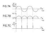
- FIGs. 7A through 7C are a timing diagram for illustrating an operation of the zero crossing signal generator 408 shown in FIG. 6.
- IV represents an input voltage of the full-wave rectifier 602 of the zero crossing signal generator 408.
- FR represents the full-wave rectified alternating current power from the full-wave rectifier 602.
- PS represents the pulse signal PS of a predetermined width generated by the pulse signal generator 604.
- the controller 410 generates first and second control signals CS1 and CS2 to control the first and second switches 402 and 404 according to the operation state of the gas boiler 20 in response to the pulse signal PS from the zero crossing signal generator 408, respectively.
- the controller 410 controls a duty cycle of the first and second control signals CS1 and CS2 during a mode change of the gas boiler 20 in order to control a phase of the two-way pump driving voltage.
- FIG. 5D is a view for showing a magnitude of the power which is applied to the two-way pump motor 400 during forward and reverse rotations thereof.
- a time t0 represents a time that starts a hot-water mode by means of reverse rotation of the two-way pump motor 400.
- a first time interval T1 from the time t0 to a time t1 represents a time interval that continues a reverse rotation of the two-way pump motor 400 to thereby maintain a hot-water mode.
- the time t1 represents a time that stops a hot-water mode.
- a second time interval T2 from the time t1 to a time t2 represents a time interval to remove loss according to load by an inertia force of the two-way pump motor 400 when a hot-water mode is switched to a heating mode.
- the second time interval T2 is 2 seconds.
- the time t2 represents a time that starts a heating mode by means of forward rotation of the two-way pump motor 400.
- a third time interval T3 from the time t2 to a time t3 is a time interval that forward rotates the two-way pump 204 slowly in such a manner that a speed of the two-way pump motor 400 is increased as time goes by.
- a time t4 is the time when the heating mode starts to stop.
- a fifth time interval T5 from the time t4 to a time t5 is a time interval that reversely rotates the two-way pump 204 slowly in such a manner that a speed of the two-way pump motor 400 is reduced as time goes by.
- FIG. 8 is a flow chart for illustrating a two-way pump control method according to an embodiment of the present invention.
- step S101 the controller 410 judges whether or not a hot-water mode of the gas boiler 20 is selected.
- step S101 when the hot-water mode of the gas boiler 20 is selected, the controller 410 judges whether or not the two-way pump 204 drives(step S102).
- step S102 when the two-way pump 204 stops, the controller 410 reversely rotates the two-way pump 204 at a time t0 or a time t6 as shown in FIG. 5D(step S103).
- the zero crossing signal generator 408 generates the pulse signal PS of a predetermined width and outputs it to the controller 410.
- the controller 410 applies a first control signal CS1 of a high level and a second control signal CS2 of a low level to first and second input terminals DI1 and DI2 in response to the pulse signal PS from the zero crossing signal generator 408, respectively.
- the driver 406 turns off and on the first and second switches 402 and 404 in response to the first control signal CS1 of a high level and the second control signal CS2 of a low level from the controller 410, respectively. Accordingly, AC power of 220 volt is applied to the two-way pump motor 400 for a first time interval T1 as shown in FIG. 5D to thereby reversely rotate the two-way pump 204. Then, the routine returns to step S101. When it is judged that the two-way pump 204 drives in step S102, the controller 410 judges whether or not the two-way pump 204 forward rotates(step S104).
- step S104 when the two-way pump 204 forward rotates, the controller 410 stops the two-way pump 204 at low speed in such a manner that a speed of the two-way pump motor 400 is gradually reduced for the fifth time interval T5, that is, 5 seconds as time goes by and moves the ball 304 of the two-pump 204 from the hot-water outlet 312 to the heating outlet 310 within the housing 302(step S105).
- the controller 410 in response to the pulse signal PS from the zero crossing signal generator 408 applies a first control signal CS1, a duty cycle of which is controlled by the first input terminal DI1 of the driver 406 for the fifth time interval T5 from the time t4 to the time t5.
- the first control signal CS1 is applied to the first input terminal DI1 of the driver 406 in such a manner that the duty cycle thereof is gradually reduced as time goes by from the time t4 to the time t5.
- the controller 410 applies the second control signal CS2 of a high level for the fifth time interval T5. Accordingly, the driver 406 turns on the first switch 402 for 5 seconds so that AC power the magnitude of which is controlled from AC source (AC 220) as shown in FIG. 7C is applied to the two-way pump motor 400. Accordingly, the two-way pump motor 400 slowly stops in such a manner that the speed of the two-way pump motor 400 is gradually reduced for 5 seconds from the time t4 to the time t5.
- step S104 the controller 410 continues the reverse rotation of the two-way pump 204 for a fourth time interval T4 from the time t3 to the time t4 to thereby maintain the hot-water mode(step S106).
- step S101 when the hot-water mode of the gas boiler 20 is not selected, the controller 410 judges whether or not a heating mode is selected(step S107).
- step S107 when the heating mode of the gas boiler is not selected, the controller 410 judges that a stop mode of the gas boiler 20 is selected and judges whether or not the two-way pump 204 drives(step S108).
- step S108 when the two-way pump 204 drives, the controller 410 judges whether or not the two-way pump 204 forward rotates(step S109).
- step S109 As a result of the judgement in step S109, when the two-way pump 204 forward rotates, the controller 410 stops the two-way pump 204 at low speed in such a manner that a speed of the two-way pump motor 400 is gradually reduced for 5 seconds as time goes by via the same method in the step S105. Then the total operation finishes.
- the controller 410 stops the two-way pump 204 at high speed(step S111). Then the total operation finishes.
- step S107 when the stop mode of the gas boiler 20 is not selected, the controller 410 judges that a heating mode of the gas boiler 20 is selected and judges whether or not the two-way pump 204 drives(step S112).
- step S112 when the two-way pump 204 stops, the controller 410 slowly performs a forward rotation of the two-way pump 204 for 5 seconds and moves the ball 304 from a heating outlet 310 to a hot-water outlet 312 within the housing 302(step S113).
- the controller 410 in response to the pulse signal PD from the zero crossing signal generator 408 applies a first control signal CS1 a duty cycle of which is controlled, by the first input terminal DI1 of the driver 406 for the third time interval T3(5 seconds) from the time t2 to the time t3.
- the first control signal CS1 is applied to the first input terminal DI1 of the driver 406 in such a manner that the duty cycle thereof is gradually increased as time goes by from the time t2 to the time t3.
- the controller 410 applies the second control signal CS2 of a high level for the fifth time interval T3.
- the driver 406 turns on the first switch 402 for 5 seconds so that AC power the magnitude of which is controlled from AC source (AC 220) as shown in FIG. 7C is applied to the two-way pump motor 400. Accordingly, the two-way pump motor 400 forward rotates in such a manner that the speed of the two-way pump motor 400 is gradually increased for 5 seconds from the time t2 to the time t2.
- the ball 304 of the two-way pump 204 moves from the heating outlet 310 to the hot-water outlet 312 within the housing 302, an opening/closing hole is slowly closed. Accordingly, a sudden change of a heating water current is prevented so that impact noise is prevented. Then the routine returns to step S101.
- step S104 When it is judged that the two-way pump 204 reversely rotates in step S104, the controller 410 continues the reverse rotation of the two-way pump 204 for a fourth time interval T4 from the time t3 to the time t4 to thereby maintain the hot-water mode(step S106). Then the routine returns to step S101.
- the two-way pump 204 stops at time tl which was reversely rotating in the hot-water mode, it remains in a stop state for the second time interval T2, that is, for 2 seconds, from the time t1 to the time 2 to remove loss according to power load by an inertia force of the two-way pump motor 400.
- step S112 the controller 410 judges whether or not the two-way pump 204 forward rotates (step S114).
- step S114 when the two-way pump 204 reversely rotates, the controller 410 stops the two-way pump 204 at high speed(step S115).
- step S115 When it is judged that the two-way pump 204 forward rotates, the controller 410 continues the forward rotation of the two-way pump 204 for the fourth time interval T4 from the time t3 to the time t4 to thereby maintain a heating mode.
- the two-way pump of a gas boiler can simplify a pipe connecting structure in a gas boiler.
- a two-way pump driving voltage that is, a speed of a two-way pump motor is controlled.
- a ball of the two-way pump moves within a pump housing up and down, it slowly opens and closes an opening/closing hole. Accordingly, a sudden change of a heating water current is prevented so that impact noise is prevented.
Landscapes
- Engineering & Computer Science (AREA)
- Power Engineering (AREA)
- Mechanical Engineering (AREA)
- General Engineering & Computer Science (AREA)
- Steam Or Hot-Water Central Heating Systems (AREA)
Priority Applications (1)
| Application Number | Priority Date | Filing Date | Title |
|---|---|---|---|
| EP99108672A EP1054218A1 (de) | 1999-05-17 | 1999-05-17 | Zweiwege-Pumpe für gasbeheizten Kessel, Steuerschaltung und Steuerverfahren dafür |
Applications Claiming Priority (1)
| Application Number | Priority Date | Filing Date | Title |
|---|---|---|---|
| EP99108672A EP1054218A1 (de) | 1999-05-17 | 1999-05-17 | Zweiwege-Pumpe für gasbeheizten Kessel, Steuerschaltung und Steuerverfahren dafür |
Publications (1)
| Publication Number | Publication Date |
|---|---|
| EP1054218A1 true EP1054218A1 (de) | 2000-11-22 |
Family
ID=8238090
Family Applications (1)
| Application Number | Title | Priority Date | Filing Date |
|---|---|---|---|
| EP99108672A Withdrawn EP1054218A1 (de) | 1999-05-17 | 1999-05-17 | Zweiwege-Pumpe für gasbeheizten Kessel, Steuerschaltung und Steuerverfahren dafür |
Country Status (1)
| Country | Link |
|---|---|
| EP (1) | EP1054218A1 (de) |
Cited By (3)
| Publication number | Priority date | Publication date | Assignee | Title |
|---|---|---|---|---|
| EP1598588A1 (de) * | 2004-05-21 | 2005-11-23 | Giorgio Scanferla | Kessel für kombinierte Heizwasser- und Sanitärwasserherstellung mit einer Anordnung zur Vermeidung vom Wasserschlag in dem Bypass- Kreislauf |
| US20090283057A1 (en) * | 2005-11-22 | 2009-11-19 | Kyungdong Navien Co., Ltd. | Hot-Water Supplying System of Boiler Equipped With Dual Pipe Heat Exchanger |
| CN112664998A (zh) * | 2021-01-11 | 2021-04-16 | 青岛海信日立空调系统有限公司 | 一种多联热泵水暖系统及其控制方法 |
Citations (8)
| Publication number | Priority date | Publication date | Assignee | Title |
|---|---|---|---|---|
| DE2104090A1 (de) * | 1970-04-17 | 1971-11-04 | Joh. Vaillant Kg, 5630 Remscheid | Anordnung bei einer Warmwasserumlaufheizung mit Brauchwassererhitzer |
| JPH06280782A (ja) * | 1993-03-30 | 1994-10-04 | Mitsubishi Electric Corp | ポンプ装置 |
| US5486089A (en) * | 1994-02-28 | 1996-01-23 | Daewoo Electronics Co., Ltd. | Directional changeover pump |
| GB2296608A (en) * | 1994-12-07 | 1996-07-03 | Mitsubishi Electric Corp | Motor drive unit for a fan |
| EP0739086A1 (de) * | 1995-04-19 | 1996-10-23 | Landis & Gyr Technology Innovation AG | Verfahren und Vorrichtung zum Ansteuern von Synchronmotoren |
| DE19638248A1 (de) * | 1995-09-20 | 1997-03-27 | Fasto Nefit Bv | Wasserstoßdämpfer sowie eine mit einem Wasserstoßdämpfer ausgerüstete Pumpe |
| GB2318179A (en) * | 1996-10-11 | 1998-04-15 | Blue Circle Heating Ltd | Pump control for central heating systems |
| JPH10281477A (ja) * | 1997-03-28 | 1998-10-23 | Daewoo Electron Co Ltd | ガスボイラの双方向ポンプ制御方法及び装置 |
-
1999
- 1999-05-17 EP EP99108672A patent/EP1054218A1/de not_active Withdrawn
Patent Citations (9)
| Publication number | Priority date | Publication date | Assignee | Title |
|---|---|---|---|---|
| DE2104090A1 (de) * | 1970-04-17 | 1971-11-04 | Joh. Vaillant Kg, 5630 Remscheid | Anordnung bei einer Warmwasserumlaufheizung mit Brauchwassererhitzer |
| JPH06280782A (ja) * | 1993-03-30 | 1994-10-04 | Mitsubishi Electric Corp | ポンプ装置 |
| US5486089A (en) * | 1994-02-28 | 1996-01-23 | Daewoo Electronics Co., Ltd. | Directional changeover pump |
| GB2296608A (en) * | 1994-12-07 | 1996-07-03 | Mitsubishi Electric Corp | Motor drive unit for a fan |
| EP0739086A1 (de) * | 1995-04-19 | 1996-10-23 | Landis & Gyr Technology Innovation AG | Verfahren und Vorrichtung zum Ansteuern von Synchronmotoren |
| DE19638248A1 (de) * | 1995-09-20 | 1997-03-27 | Fasto Nefit Bv | Wasserstoßdämpfer sowie eine mit einem Wasserstoßdämpfer ausgerüstete Pumpe |
| GB2318179A (en) * | 1996-10-11 | 1998-04-15 | Blue Circle Heating Ltd | Pump control for central heating systems |
| JPH10281477A (ja) * | 1997-03-28 | 1998-10-23 | Daewoo Electron Co Ltd | ガスボイラの双方向ポンプ制御方法及び装置 |
| US5931379A (en) * | 1997-03-28 | 1999-08-03 | Daewoo Electronics K.K. | Method and apparatus for controlling a bi-directional pump of a gas boiler |
Non-Patent Citations (1)
| Title |
|---|
| PATENT ABSTRACTS OF JAPAN vol. 1995, no. 01 28 February 1995 (1995-02-28) * |
Cited By (3)
| Publication number | Priority date | Publication date | Assignee | Title |
|---|---|---|---|---|
| EP1598588A1 (de) * | 2004-05-21 | 2005-11-23 | Giorgio Scanferla | Kessel für kombinierte Heizwasser- und Sanitärwasserherstellung mit einer Anordnung zur Vermeidung vom Wasserschlag in dem Bypass- Kreislauf |
| US20090283057A1 (en) * | 2005-11-22 | 2009-11-19 | Kyungdong Navien Co., Ltd. | Hot-Water Supplying System of Boiler Equipped With Dual Pipe Heat Exchanger |
| CN112664998A (zh) * | 2021-01-11 | 2021-04-16 | 青岛海信日立空调系统有限公司 | 一种多联热泵水暖系统及其控制方法 |
Similar Documents
| Publication | Publication Date | Title |
|---|---|---|
| US4907737A (en) | Electronic control system for a gas-fired/hot air furnace with induced draft blower | |
| EP1054218A1 (de) | Zweiwege-Pumpe für gasbeheizten Kessel, Steuerschaltung und Steuerverfahren dafür | |
| US5299340A (en) | Water feeding control method of a boiling clothes washing machine | |
| KR100684373B1 (ko) | 순간온수형 온수 공급 제어 장치 | |
| KR100302386B1 (ko) | 가스 보일러의 양방향 펌프, 그의 제어 회로, 및 그의 제어 방법 | |
| JP4230615B2 (ja) | 給湯装置 | |
| JP2011132853A (ja) | ファンモータ制御装置及びファンモータ制御システム | |
| US5931379A (en) | Method and apparatus for controlling a bi-directional pump of a gas boiler | |
| US4945735A (en) | Washing machine with improved pump control device for closing a valve | |
| US11221149B2 (en) | Pump device, industrial water system, method for operating an industrial water system, and self-teaching method for a delivery pump in an industrial water system | |
| CN223005114U (zh) | 电加热管、电加热装置和水路系统 | |
| JPH05126402A (ja) | 熱電併給装置 | |
| JP3589261B2 (ja) | 便器用付属装置 | |
| KR100467333B1 (ko) | 가스보일러의 양방향펌프제어방법 | |
| KR200382678Y1 (ko) | 하이브리드 순간온수형 공급 제어 장치 | |
| JP3150873B2 (ja) | 電圧監視装置 | |
| KR100223304B1 (ko) | 가스보일러의 양방향펌프제어방법 | |
| KR200369174Y1 (ko) | 연료절감을 위한 보일러 제어장치 | |
| JP2004337498A (ja) | トイレ装置 | |
| JPH0972633A (ja) | 冷媒制御弁及び冷媒制御弁の駆動方法 | |
| JP3065194B2 (ja) | 浴室暖房装置 | |
| CN1274808A (zh) | 燃气锅炉的双向式泵及其控制电路和控制方法 | |
| KR950000936B1 (ko) | 고출력 가스보일러의 표준 최대 연소대비 출력제한 제어방법 및 그 장치 | |
| KR200158535Y1 (ko) | 냉,온수공급장치의 냉수임시가열회로 | |
| JPS6014125A (ja) | 液面検知回路 |
Legal Events
| Date | Code | Title | Description |
|---|---|---|---|
| PUAI | Public reference made under article 153(3) epc to a published international application that has entered the european phase |
Free format text: ORIGINAL CODE: 0009012 |
|
| AK | Designated contracting states |
Kind code of ref document: A1 Designated state(s): BE DE ES FR GB IT NL |
|
| AX | Request for extension of the european patent |
Free format text: AL;LT;LV;MK;RO;SI |
|
| 17P | Request for examination filed |
Effective date: 20010417 |
|
| AKX | Designation fees paid |
Free format text: BE DE ES FR GB IT NL |
|
| 17Q | First examination report despatched |
Effective date: 20020917 |
|
| RAP1 | Party data changed (applicant data changed or rights of an application transferred) |
Owner name: DAEWOO GASBOILER CO., LTD. |
|
| STAA | Information on the status of an ep patent application or granted ep patent |
Free format text: STATUS: THE APPLICATION HAS BEEN WITHDRAWN |
|
| 18W | Application withdrawn |
Effective date: 20031230 |