EP1054246A2 - Verfahren und Vorrichtung zum Prüfen von Reifen - Google Patents
Verfahren und Vorrichtung zum Prüfen von Reifen Download PDFInfo
- Publication number
- EP1054246A2 EP1054246A2 EP00110447A EP00110447A EP1054246A2 EP 1054246 A2 EP1054246 A2 EP 1054246A2 EP 00110447 A EP00110447 A EP 00110447A EP 00110447 A EP00110447 A EP 00110447A EP 1054246 A2 EP1054246 A2 EP 1054246A2
- Authority
- EP
- European Patent Office
- Prior art keywords
- contrast
- values
- radius
- tire
- angle
- Prior art date
- Legal status (The legal status is an assumption and is not a legal conclusion. Google has not performed a legal analysis and makes no representation as to the accuracy of the status listed.)
- Withdrawn
Links
Images


Classifications
-
- G—PHYSICS
- G01—MEASURING; TESTING
- G01M—TESTING STATIC OR DYNAMIC BALANCE OF MACHINES OR STRUCTURES; TESTING OF STRUCTURES OR APPARATUS, NOT OTHERWISE PROVIDED FOR
- G01M17/00—Testing of vehicles
- G01M17/007—Wheeled or endless-tracked vehicles
- G01M17/02—Tyres
- G01M17/027—Tyres using light, e.g. infrared, ultraviolet or holographic techniques
Definitions
- the invention relates to a tire test method in which before and after a change in tire pressure with coherent radiation, one interferogram of the tire surface generated and from the interferogram the information about existing defects of the Tire obtained and provided as a contrast profile.
- the invention further relates to a tire testing device with an air pressure device for changing the tire pressure as well as a test head and a calculator that with before and after a change in air pressure coherent radiation each produce an interferogram of the tire surface, whereby from information about existing defects in the tire is obtained from the interferogram and be provided as a contrast profile.
- DE 4231578 A1 describes a method for determining the structural strength of Tire known in which the tire is illuminated with coherent light from the tire backscattered radiation split into two partial beams in a two-beam interferometer one of the two partial radiations against the other in the two-beam interferometer Partial radiation is tilted (shearing) in the two-beam interferometer one of the two Partial radiation is gradually shifted in phase, which is scattered back by the test object and divided into the two partial radiations in the two-beam interferometer and again merged radiation through components imaging the surface of the tire large opening is supplied to an electronic image sensor system and by the Image sensor system digitized signals and in an image processing system a modulo 2 ⁇ image are processed and the modulo 2 ⁇ image into one Output gray scale image is confirmed.
- the above-mentioned method is further developed by that the output gray value image is partially differentiated in such a way that a second one Output gray value image is generated the same gray value image and this against the output gray value image geometrically shifted in the shearing direction and by one over the entire Image area constant gray value is changed and the manipulated second gray value image is subtracted from the output gray value image, and thus a resulting gray value image arises, at which possibly existing defects of a tire can be recognized.
- DE 3 624 589 A1 describes a method for the non-destructive testing of Vehicle tire known, in which by means of holographic interferometry or Shearography using the tire surface to be examined briefly for deformation an energetic laser pulse is illuminated.
- the interferograms obtained or Shearograms are recorded in a time-saving manner using a thermoplastic camera.
- the Method is carried out on a device in which the tire to be tested step by step along a tire transport route with various treatment stations including a vacuum container provided with the pulse device.
- the above methods also have the disadvantage that not only defects or Defects that weaken the structure of the tire, but also so-called Shocks are recorded and displayed, which mean a structural reinforcement in the tire.
- Shocks are recorded and displayed, which mean a structural reinforcement in the tire.
- the Evaluation of the test results which are output in the form of a graphic, could possibly an experienced operator the flaws from the bumps differentiate.
- it would be desirable that these decisions are not based the experience of the operator, but correct and binding in the execution of the Test procedure itself is taken.
- the invention has for its object a tire testing method and To create device, thereby making a safe distinction between defects that Structural weakening mean, and hits that signify structural reinforcement are hit can be.
- the method specified above is characterized in that that the contrast profile is scanned for contrast values according to angle and radius, that the Contrast values and the angle and radius are saved that the contrast values statistically evaluated and the shapes and mutual positions of contrast areas to each other are determined, their contrast values at a given place value lie that due to the shapes and the mutual positions of the contrast areas Assignment of the contrast areas to imperfections or bumps is carried out.
- Contrast areas are defined as areas whose contrast values differ significantly from those Distinguish contrast values of their surroundings.
- the contrasts by brightness or gray values or formed by colors in a formation of the tire surface are the Contrast areas dark spots on a light background or bright spots on a dark background or colored spots on a neutral background. From the forms and the mutual Layers of these contrast areas can now be reliably distinguished from imperfections and Carry out impacts, since imperfections are aligned radially and a contrast area cause to which there is no further, radial in its environment in the image of the tire aligned contrast range there. In addition, impacts are also aligned radially and cause two contrast areas that have a predetermined maximum distance and between which there is an area of minimal contrast areas.
- a An advantageous embodiment of the method according to the invention is characterized in that that the statistical evaluation of the frequency distribution of the contrast values over the Radius is performed. This advantageously takes the criterion into account worn that flaws extend radially, because this feature by this type of statistical evaluation is filtered out.
- the result of this evaluation represents represents a reliable image contrast evaluation in an advantageous manner.
- the third threshold serves in advantageously to filter out image disturbances that are not radial and also not over extend an entire radius.
- the third threshold is less than the first threshold.
- the first and third threshold values could also be chosen to be the same size. The possibility to choose these threshold values differently, however, gives one another possibility to make the result of the statistical evaluation more obvious, in the contrast areas become larger as the first threshold is lowered. It can also be taken into account that the second maximum in the event of an impact can have a smaller value than the first maximum.
- the image images of the source images 2 are carried out using CCD elements.
- CCD elements To one To perform image averaging, a large number of source images 2 are recorded, and these source images form a first image sequence.
- a second set of Source images retracted after some air is released from the tire under test has been. After averaging the image, this results in the second image sequence.
- Method steps 4 and 6 are the algorithms after the phase shift and Shearing procedures performed as described in the prior art. By Folding or deduction of the images before and after deflation in process step 10 a modulated phase image, a so-called sawtooth image, is generated, as indicated at 12.
- the modulated phase image is then demodulated in method step 14, wherein demodulated phase image after using a filter technology known per se results, as shown in block 16. After differentiating the phase image in Shearing direction in method step 18 results in the differentiated phase image, as in Block 20 is shown.
- This differentiated phase image is now evaluated according to the invention to determine between To be able to distinguish between imperfections and bumps.
- the image pixels within a mask are sorted by angle and radius snapped, and all pixels are output and saved that exceed a set first threshold.
- the so-called threshold value file 24 built up.
- the threshold value file with the target of Error evaluation is evaluated, and in step 28, between A distinction is made between structural weakening (imperfection) and stiffening (impact). Then it will The result is displayed and the pictures as well as the information about the defects are shown in the Memory 30 stored.
- the method according to the invention thus follows the previously known Tire testing method and relates in particular to the evaluation of the image data Detection and differentiation of defects and bumps.
- the process consists of initially covering an area of the tire surface is illuminated with coherent light in the infrared range by laser diodes, followed by a Image is captured by CCD elements or CCD camera.
- an optic Use that enables both phase shifting and shearing.
- To the Eliminate the influence of interference or vibrations during image acquisition an image averaging of multiple source images is already carried out during image acquisition.
- the Image evaluation is carried out by algorithms which are known per se and which serve the purpose of To convert the intensity information of the CCD camera into phase information.
- the image area is hidden with the help of a mask, but not for the evaluation of defects should be used.
- Following these procedural steps is the picture inside the mask is scanned for angle and radius, and there are all points output whose values are above a specified threshold.
- To Frequency and sum formation over the radius is followed by a defect detection Consideration of frequencies and sums over the angle. The distinction between Flaw and bump occurs by examining the surroundings of an alleged one Missing part.
- the threshold value file which is created by rasterizing the mask, contains the brightness values with angle and radius above the threshold value. Since the step size for the screening is small, but the angle and radius are rounded, a multiple occurrence of a pixel coordinate is possible.
- An example of such a table is as follows: Angle (°) Radius (mm) Brightness value 10th 198 35 10th 198 40 10th 199 38 30th 203 70 30th 202 69
- the definition of the mask, the radius and the angle result from FIGS. 2 and 3.
- For further evaluation of the threshold value file in step 26 (FIG. 1) several tables are created and the data from the threshold value file into the tables read. The transfer of the data with angle and radius results in a mapping of the Polar coordinates of the tire in a Cartesian coordinate system, creating the further Evaluation is facilitated.
- the entries from the threshold value file according to radius and angle are stored as an X coordinate and as a Y coordinate in a frequency table and a value table.
- the frequency table is created by each entry in the threshold value file increasing the counter in the corresponding cell according to the angle and radius in Figure 4.
- the implementation of the table given above results in a frequency table according to FIG. 4 that an entry is made in the cell defined by the angle of 10 ° and the radius of 198 mm 2 "and the cell defined by the angle of 30 ° and the radius of 203 mm If the table in FIG.
- the value would be in the cell, which is defined by an angle of 10 ° and a radius of 198 mm 75 "and the value 38 is entered in the cell, which is defined by the angle of 10 ° and a radius of 199 mm.
- the cell which is defined by the angle of 30 ° and the radius of 203 mm, is entered entered the value 70, and in the cell, which is defined by the angle of 30 ° and the radius of 202 mm, the value 69 ".
- each value from the threshold value file is added to the corresponding cell.
- a cell is defined by the same value for angle and radius.
- FIG. 5 shows an example of an image with defects and image disturbances, which are generated by noise or other errors in the image processing.
- the defects extend over almost the entire mask width, and the defects are set up radially. These two features are taken into account or evaluated in the subsequent supply of defects.
- the column sums of the frequency table or the value table are formed to search for defects. This gives frequency sums over the angle, ie a row which contains the sums of the columns from the frequency table in FIG. 4. A row containing the totals of the values of the columns in the table of values is obtained as the sum of values over the angle.
- the example of the value sum table is shown in FIG. 6, the value being formed after the sum of the table columns in the result line at an angle of 10 ° 113 "and at an angle of 30 ° the value 139 "is obtained.
- the frequency sum table is also operated in an analogous manner.
- FIG. 7A shows the threshold table in Cartesian Coordinates, whereby no numerical values but brightness or gray values are entered.
- FIG. 7B shows a curve which results from the threshold value table of FIG the sums over the radius are plotted against the angle.
- Figure 7A there are two contrast areas in this mask that belong to imperfections and two Contrast areas that belong to image disturbances.
- a Threshold value set as indicated in Figure 7B, so that by appropriate Pulse formation only the two pulses remain, as shown in FIG. 7C, and the the defects or bumps can be assigned.
- the threshold in Figure 7D can be set relatively high in order to reliably hide image interference.
- Figures 8A to 8C illustrate the distinction between defects and bumps. Since bumps, in contrast to imperfections, do not represent a safe risk for motor vehicle tires represent, a clear distinction must be made between the defect and the joint. To are evaluated as characteristic features that a shock by two maxima too recognize that occur mirrored at a minimum. The maximum distance between the maxima can be preset. A defect is characterized in that it is accompanied by two minima, and that at a precisely defined distance none further maximum is located. To differentiate between bumps and imperfections, the Environment of each maximum.
- FIG. 8A shows the image of a mask in which a defect and an impact occur. Becomes the table of FIG. 8A converted into a curve in accordance with the summary tables the representation of Figure 8B.
- a set another threshold which is either equal to the second threshold or is chosen smaller. The lower the threshold within the distinction from Flaw and joint is set, the wider the contrast areas, which are then examined can be.
- FIG. 8C shows a pulse sequence which results from the implementation of the curve from FIG. 8B results in impulses.
- a window is moved over the pulse train
- Length L defines the area for examining the surroundings of a contrast area.
- At the length L is an empirical value that is entered into the system. If two maxima appear in the window, it is decided that the one in question Maxima underlying contrast areas have been caused by a shock in other words, an impact is found at this point. If only in the window If there is a maximum, as is also shown in FIG. 8C, a defect becomes detected.
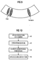
- FIG. 10 shows a block diagram of a tire testing device with which the The method described above can be carried out.
- a scanner 40 scans the Contrast profile based on angle and radius on contrast values, and in one The storage device 42 stores the contrast values according to the angle and radius.
- a statistical evaluation device 44 statistically evaluates the contrast values and determines the forms and their mutual positions of the contrast areas, their Contrast values are above a predetermined value.
- a decision-making facility 46 becomes a due to the shapes and the mutual positions of the contrast areas Assignment of the contrast areas to imperfections or bumps carried out.
Landscapes
- Physics & Mathematics (AREA)
- General Physics & Mathematics (AREA)
- Investigating Materials By The Use Of Optical Means Adapted For Particular Applications (AREA)
Abstract
Description
- eine Abtasteinrichtung, die das Kontrastprofil nach Winkel und Radius auf Kontrastwerte abtastet, durch
- eine Speichereinrichtung, in die die Kontrastwerte nach Winkel und Radius abgespeichert werden, durch
- eine Statistik-Auswertungseinrichtung, durch die die Kontrastwerte statistisch ausgewertet und die Formen und deren gegenseitige Lagen der Kontrastbereiche zueinander bestimmt werden, deren Kontrastwerte über einem vorgegebenen Stellenwert liegen, und durch
- eine Entscheidungseinrichtung, durch die aufgrund der Formen und der gegenseitigen Lagen der Kontrastbereiche eine Zuordnung der Kontrastbereiche zu Fehlstellen oder Stößen durchgeführt wird.
| Winkel (°) | Radius (mm) | Helligkeitswert |
| 10 | 198 | 35 |
| 10 | 198 | 40 |
| 10 | 199 | 38 |
| 30 | 203 | 70 |
| 30 | 202 | 69 |

Claims (12)
- Reifenprüfverfahren, bei dem vor und nach einer Änderung im Reifendruck mit kohärenter Strahlung jeweils ein Interferogramm der Reifenoberfläche erzeugt und aus dem Interferogramm die Informationen über vorhandene Fehlstellen des Reifens gewonnen und als Kontrastprofil bereitgestellt werden, dadurch gekennzeichnet, daßdas Kontrastprofil nach Winkel und Radius auf Kontrastwerte abgetastet wird, daßdie Kontrastwerte und der Winkel und Radius abgespeichert werden, daßdie Kontrastwerte statistisch ausgewertet und die Formen und die gegenseitigen Lagen von Kontrastbereichen zueinander bestimmt werden, deren Kontrastwerte bei einem vorgegebenen Stellenwert liegen, daßaufgrund der Formen und der gegenseitigen Lagen der Kontrastbereiche eine Zuordnung der Kontrastbereiche zu Fehlstellen oder Stößen durchgeführt wird.
- Verfahren nach Anspruch 1, dadurch gekennzeichnet, daß nur die Kontrastwerte, die oberhalb eines zweiten Schwellenwertes liegen, in einer Schwellenwertdatei abgespeichert werden.
- Verfahren nach Anspruch 1, dadurch gekennzeichnet, daß die statistische Auswertung über die Häufigkeitsverteilung der Kontrastwerte über dem Radius durchgeführt wird.
- Verfahren nach Anspruch 1, dadurch gekennzeichnet, daß die statistische Auswertung durchgeführt wird über eine Häufigkeitstabelle der Kontrastwerte, bei der jeder Eintrag in der Schwellenwertdatei den Zähler in der entsprechenden Zelle nach Winkel und Radius erhöht, und eine Häufigkeitssummentabelle der Kontrastwerte, in der die Summen der Spalten der Häufigkeitstabelle über dem Winkel gebildet werden.
- Verfahren nach Anspruch 1, dadurch gekennzeichnet, daß die statistische Auswertung über die Kontrastwerteverteilung der Kontrastwerte über dem Radius durchgeführt wird.
- Verfahren nach Anspruch 1, dadurch gekennzeichnet, daß die statistische Auswertung durchgeführt wird über eine Kontrastwertetabelle, in der jeder Kontrastwert aus der Schwellenwertdatei in die entsprechende Zelle nach Winkel und Radius addiert wird, und eine Kontrastwert-Summentabelle, in der die Summen der Spalten der Kontrastwerttabelle aus der Schwellenwertdatei über dem Winkel gebildet werden.
- Verfahren nach Anspruch 1, dadurch gekennzeichnet, daß eine gewichtete Multiplikation der Häufigkeits-Summentabelle und der Kontrastwerte-Summentabelle durchgeführt wird.
- Verfahren nach Anspruch 1, dadurch gekennzeichnet, daß die Zuordnung der Kontrastbereiche zu Fehlstellen oder Stößen durch Auswertung der Häufigkeitssummen der Kontrastwerte oder der Kontrastwertesummen durchgeführt wird.
- Verfahren nach Anspruch 1, dadurch gekennzeichnet, daß nur solche Häufigkeitssummen oder Kontrastwertesummen ausgewertet werden, die einen dritten Schwellenwert übersteigen.
- Verfahren nach Anspruch 1, dadurch gekennzeichnet, daß der dritte Schwellenwert kleiner als der erste Schwellenwert ist.
- Verfahren nach Anspruch 1, dadurch gekennzeichnet, daß die Zuordnung eines Kontrastbereiches zu einer Fehlstelle bzw. einem Stoß dadurch durchgeführt wird, daß ein Fenster vorgegebener Länge über eine durch die Summen gebildete Kurve bewegt und eine Fehlstelle festgestellt wird, wenn jeweils nur ein Maximum in dem Fenster erfaßt wird, und ein Stoß festgestellt wird, wenn zwei Maxima der Kurve in dem Fenster erfaßt werden.
- Reifenprüfvorrichtung mit einer Luftdruckeinrichtung zur Änderung des Reifendrucks sowie einem Prüfkopf und einem Rechner, die vor und nach einer Änderung im Luftdruck mit kohärenter Strahlung jeweils ein Interferogramm der Reifenoberfläche erzeugen, wobei aus dem Interferogramm die Informationen über vorhandene Fehlstellen des Reifens gewonnen und als Kontrastprofil bereitgestellt werden, gekennzeichnet ist durch:eine Abtasteinrichtung, die das Kontrastprofil nach Winkel und Radius auf Kontrastwerte abtastet, durcheine Speichereinrichtung, in die die Kontrastwerte nach Winkel und Radius abgespeichert werden, durcheine Statistik-Auswertungseinrichtung, durch die die Kontrastwerte statistisch ausgewertet und die Formen und deren gegenseitige Lagen der Kontrastbereiche zueinander bestimmt werden, deren Kontrastwerte über einem vorgegebenen Stellenwert liegen, und durcheine Entscheidungseinrichtung, durch die aufgrund der Formen und der gegenseitigen Lagen der Kontrastbereiche eine Zuordnung der Kontrastbereiche zu Fehlstellen oder Stößen durchgeführt wird.
Applications Claiming Priority (2)
| Application Number | Priority Date | Filing Date | Title |
|---|---|---|---|
| DE1999122775 DE19922775A1 (de) | 1999-05-18 | 1999-05-18 | Reifenprüfverfahren |
| DE19922775 | 1999-05-18 |
Publications (2)
| Publication Number | Publication Date |
|---|---|
| EP1054246A2 true EP1054246A2 (de) | 2000-11-22 |
| EP1054246A3 EP1054246A3 (de) | 2003-05-07 |
Family
ID=7908396
Family Applications (1)
| Application Number | Title | Priority Date | Filing Date |
|---|---|---|---|
| EP00110447A Withdrawn EP1054246A3 (de) | 1999-05-18 | 2000-05-16 | Verfahren und Vorrichtung zum Prüfen von Reifen |
Country Status (2)
| Country | Link |
|---|---|
| EP (1) | EP1054246A3 (de) |
| DE (1) | DE19922775A1 (de) |
Family Cites Families (2)
| Publication number | Priority date | Publication date | Assignee | Title |
|---|---|---|---|---|
| DE19501073A1 (de) * | 1995-01-16 | 1996-08-01 | Nova C O R D Ag | Bildverarbeitungsverfahren zur Ermittlung der Strukturfestigkeit eines Prüfobjektes mit diffus streuender Oberfläche |
| DE59609853D1 (de) * | 1996-08-06 | 2002-12-12 | Nova C O R D Ag Schaan | Verfahren zur Ermittlung von Reifendefekten |
-
1999
- 1999-05-18 DE DE1999122775 patent/DE19922775A1/de not_active Withdrawn
-
2000
- 2000-05-16 EP EP00110447A patent/EP1054246A3/de not_active Withdrawn
Also Published As
| Publication number | Publication date |
|---|---|
| DE19922775A1 (de) | 2000-11-23 |
| EP1054246A3 (de) | 2003-05-07 |
Similar Documents
| Publication | Publication Date | Title |
|---|---|---|
| DE10081029B4 (de) | Bildbearbeitung zur Vorbereitung einer Texturnalyse | |
| DE102018129425B4 (de) | System zur Erkennung eines Bearbeitungsfehlers für ein Laserbearbeitungssystem zur Bearbeitung eines Werkstücks, Laserbearbeitungssystem zur Bearbeitung eines Werkstücks mittels eines Laserstrahls umfassend dasselbe und Verfahren zur Erkennung eines Bearbeitungsfehlers eines Laserbearbeitungssystems zur Bearbeitung eines Werkstücks | |
| EP2732236B1 (de) | Optische vorrichtung und verfahren zur reifenprüfung | |
| EP0012724B1 (de) | Verfahren zur maschinellen Beurteilung der Druckqualität eines Druckerzeugnisses sowie Vorrichtung zu dessen Durchführung | |
| DE4413963C2 (de) | Anordnung zur Erkennung von Fingerabdrücken | |
| DE69734733T2 (de) | Ortsbestimmung einer trennung in einer verformbaren struktrur ( reifen ) | |
| DE3937950A1 (de) | Verfahren zum pruefen optischer oberflaechen | |
| WO1999004248A9 (de) | Verfahren zur automatischen erkennung von oberflächenfehlern an rohkarosserien und vorrichtung zur durchführung des verfahrens | |
| DE60307967T2 (de) | Bildverarbeitungsverfahren für die untersuchung des erscheinungsbildes | |
| DE10062251C2 (de) | Vorrichtung und Verfahren zur Qualitätsüberprüfung eines Körpers | |
| EP2619525B1 (de) | Verfahren zum optischen antasten einer kante in oder an einem oberlächenbereich | |
| DE2620611C2 (de) | ||
| WO2018233780A1 (de) | Verfahren und vorrichtung zur vermessung von karosserieschäden | |
| DE102012104282A1 (de) | Verfahren und Vorrichtung zur Inspektion von Oberflächen eines untersuchten Objekts | |
| DE102011081668A1 (de) | Vorrichtung und Verfahren zur Bestimmung der Form des Endes einer Schweißnaht | |
| EP4416459B1 (de) | Verfahren zum prüfen von reifen | |
| EP1332334A1 (de) | Messeinrichtung zur berührungslosen messung von reifen | |
| DE3505331A1 (de) | Verfahren und geraet zur vermessung des bei der eindringhaertepruefung in einer probe hinterlassenen eindrucks | |
| EP4306322A1 (de) | Verfahren zur prüfung von tiefdruckzylindern und tiefdruckplatten | |
| DE102021123880A1 (de) | Verfahren und Vorrichtung zur Erkennung von lokalen Fehlern auf einer spiegelnden Oberfläche | |
| DE19840969A1 (de) | Verfahren und Vorrichtung zum optoelektronischen Ermitteln der Tragbilder an Zahnflanken von Zahnrädern | |
| DE19501073A1 (de) | Bildverarbeitungsverfahren zur Ermittlung der Strukturfestigkeit eines Prüfobjektes mit diffus streuender Oberfläche | |
| EP0823623B1 (de) | Verfahren zur Ermittlung von Reifendefekten | |
| DE3113440A1 (de) | "verfahren zur ueberpruefung von gleichartigen objekten auf fehler" | |
| DE10063756A1 (de) | Verfahren und Vorrichtung zum Kompensieren einer Dejustage einer Bilderzeugungsvorrichtung |
Legal Events
| Date | Code | Title | Description |
|---|---|---|---|
| PUAI | Public reference made under article 153(3) epc to a published international application that has entered the european phase |
Free format text: ORIGINAL CODE: 0009012 |
|
| AK | Designated contracting states |
Kind code of ref document: A2 Designated state(s): AT BE CH CY DE DK ES FI FR GB GR IE IT LI LU MC NL PT SE |
|
| AX | Request for extension of the european patent |
Free format text: AL;LT;LV;MK;RO;SI |
|
| PUAL | Search report despatched |
Free format text: ORIGINAL CODE: 0009013 |
|
| STAA | Information on the status of an ep patent application or granted ep patent |
Free format text: STATUS: THE APPLICATION IS DEEMED TO BE WITHDRAWN |
|
| AK | Designated contracting states |
Designated state(s): AT BE CH CY DE DK ES FI FR GB GR IE IT LI LU MC NL PT SE |
|
| AX | Request for extension of the european patent |
Extension state: AL LT LV MK RO SI |
|
| 18D | Application deemed to be withdrawn |
Effective date: 20020604 |