EP1054252A2 - Optische Messanordnung zur Bestimmung der Transmissions- und Streustrahlung - Google Patents
Optische Messanordnung zur Bestimmung der Transmissions- und Streustrahlung Download PDFInfo
- Publication number
- EP1054252A2 EP1054252A2 EP00890151A EP00890151A EP1054252A2 EP 1054252 A2 EP1054252 A2 EP 1054252A2 EP 00890151 A EP00890151 A EP 00890151A EP 00890151 A EP00890151 A EP 00890151A EP 1054252 A2 EP1054252 A2 EP 1054252A2
- Authority
- EP
- European Patent Office
- Prior art keywords
- radiation
- measuring
- capillary
- detector
- axis
- Prior art date
- Legal status (The legal status is an assumption and is not a legal conclusion. Google has not performed a legal analysis and makes no representation as to the accuracy of the status listed.)
- Granted
Links
Images


Classifications
-
- G—PHYSICS
- G01—MEASURING; TESTING
- G01N—INVESTIGATING OR ANALYSING MATERIALS BY DETERMINING THEIR CHEMICAL OR PHYSICAL PROPERTIES
- G01N21/00—Investigating or analysing materials by the use of optical means, i.e. using sub-millimetre waves, infrared, visible or ultraviolet light
- G01N21/17—Systems in which incident light is modified in accordance with the properties of the material investigated
- G01N21/47—Scattering, i.e. diffuse reflection
- G01N21/49—Scattering, i.e. diffuse reflection within a body or fluid
- G01N21/53—Scattering, i.e. diffuse reflection within a body or fluid within a flowing fluid, e.g. smoke
- G01N21/532—Scattering, i.e. diffuse reflection within a body or fluid within a flowing fluid, e.g. smoke with measurement of scattering and transmission
-
- G—PHYSICS
- G01—MEASURING; TESTING
- G01N—INVESTIGATING OR ANALYSING MATERIALS BY DETERMINING THEIR CHEMICAL OR PHYSICAL PROPERTIES
- G01N21/00—Investigating or analysing materials by the use of optical means, i.e. using sub-millimetre waves, infrared, visible or ultraviolet light
- G01N21/01—Arrangements or apparatus for facilitating the optical investigation
- G01N21/03—Cuvette constructions
- G01N2021/0346—Capillary cells; Microcells
Definitions
- the invention relates to an optical measuring arrangement for determining the transmission and the scattered radiation of a measuring radiation which is present in a capillary, liquid sample, the axis of the measuring radiation being substantially perpendicular to the Axis of the capillary is directed, with a first detector for detecting the transmission radiation, which is arranged in the area of the axis of the measuring radiation and with an in Direction of the capillary axis at a distance from the first detector arranged second Scattered radiation detector.
- Such measuring arrangements are mainly used for the investigation of liquid media, which contain absorbent scattering bodies. These are e.g. Whole blood samples, others organic or inorganic liquids, but also liquid samples in the Environmental technology, such as Sewage samples.
- Absorption measurements can be used to determine the concentration of the ingredients of such liquids at different wavelengths in a transmission or transmitted light geometry and be carried out in a scattered light geometry, from the measured Transmission and scattered light intensities using known calibration data Samples and knowledge of the blank values (measured values when the capillary is filled with pure water) the ingredients can be determined.
- EP 0 800 074 A1 describes a device for determining the concentration of hemoglobin derivatives in an undiluted, unhemolized whole blood sample known.
- the whole blood sample is exposed to the measuring radiation in a cuvette, which different at least n monochromatic, narrow-band radiation components Has wavelength.
- a first detection device is in transmission geometry arranged on the axis of the primary beam.
- the detector has a relatively small one Beam entry surface and essentially measures radiation from the central beam.
- a second detection device arranged to detect the scattered radiation. Both detectors are connected via signal lines to an evaluation device with which the Hemoglobin derivatives can be calculated using a stored calibration matrix.
- EP 0 720 013 A2 describes a method and a device for optical determination Blood parameters have become known, an embodiment variant being in a housing arranged flow cell shows which receives the blood sample. Perpendicular to the A measuring radiation from a light source is coupled in along the axis of the flow cell on the other side of the measuring cell a first detector in a transmitted light geometry and others Detectors at different distances from the first detector each in a scattered light geometry are arranged.
- the measuring cell of the arrangement described can be connected directly to the extracorporeal blood circuit connected and used to optimize dialysis become.
- a device for measuring hematocrit in blood is known from US Pat. No. 4,745,279 with which infrared radiation in a transparent cuvette through which the Blood is led, is irradiated.
- a first detector located on the bottom of the cuvette receives diffusely scattered light from the sample, which is a measure of the oxygen saturation represents.
- a second detector, which is arranged on one side surface of the cuvette, is used for hematocrit measurement.
- the excitation light for both detectors is provided by two different ones Light sources (LEDs) are provided, each in pairs in the area of Detectors are arranged.
- a third light source which does not act on the sample, is used with another detector to generate a reference signal.
- a measuring arrangement of the type described at the outset is, for example, from US Pat EP 0 575 712 A2 known, with which directly in-vitro or in an extracorporeal blood circulation at the same time the hematocrit value and another variable, for example the sodium concentration can be determined.
- the collimated measuring beam from a light source hits perpendicular to a measuring chamber through which the blood sample flows, which is in a housing is arranged.
- Two photodetectors are used for absorption measurement, whereby the first detector in the direction of the incident light (transmission radiation) and the second is positioned away from the central direction (scattered radiation).
- the second Radiation components detected by the detector are strongly influenced by the sodium concentration, so that their quantitative determination is possible.
- the measuring radiation can at least partly through scattering and reflection processes outside the sample and partly get directly into the scattered light detector and falsify its measurement result.
- the object of the present invention is to provide a measuring arrangement as described in the introduction Kind in such a way that a meaningful as possible, unaffected by the primary radiation Measurement signal at the scattered light detector can be detected.
- the first and the second detector lie on different sides of a plane which contains the capillary axis and on which Axis of the measuring radiation is normal. Scattered radiation is thus measured - in Difference from the prior art - in a backscatter position, so that solely due to the geometric arrangement an influence of the scattered light detector by the measuring radiation is largely excluded.
- This measure allows the intensity value for the Empty measurement (water filled capillary) can be kept very low, so that a large analytical measuring range is available.
- the Measuring radiation in interaction with the scattering bodies of the sample medium, i.e. she will partly absorbed and partly scattered regardless of direction.
- the optical axis of the second detector is closed Axis of the measuring radiation arranged essentially parallel. Though considerable too Deviations from the parallel arrangement (approx. ⁇ 80 °) provide usable measurement results, of course, as long as the scattered light detector is arranged in a backscatter geometry the best results are achieved in the 0 ° position (see variant Fig. 4).
- an optical ensures the optical conductivity of the capillary wall thinner medium (e.g. air) on the outer wall of the capillary. If the capillary is in a Bore of a measuring block is arranged according to the invention between a coupling area for the measuring radiation and a decoupling area for the scattered radiation at least an optical separating element is arranged, which has an annular gap between the capillary and covers the hole. This prevents parts of the measuring radiation from being reflected and reflections or air scatter outside the capillary in the area of the second Detector.
- the capillary wall thinner medium e.g. air
- the optical separating element is particularly advantageous to use as an O-ring or quad ring, which centers the capillary in the bore of the measuring block.
- the signal quality in the scattered light detector is further increased can, if the bore of the measuring block at least between the coupling area and the decoupling area has a diffusely reflecting surface.
- the Outer wall of the capillary with the exception of the coupling area for the measuring radiation and of the coupling-out area is mirrored for the scattered radiation, or a dichroic coating having.
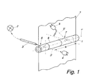
- the optical measuring arrangement shown in FIG. 1 has a capillary 1 with an axis 1 ' on, the sample to be measured being present inside the capillary, or this as part flows through an extracorporeal circuit.
- the measuring radiation is based on a Light source 2, for example, radially radiated into capillary 1 via a light guide 3, see above that the axis 3 'of the measuring radiation is substantially perpendicular to the axis 1' of the capillary 1 is directed.
- a first detector 4 is arranged to detect the transmission radiation.
- the first 4 and the second detector 5 on different Sides of a plane lie ⁇ , which contains the capillary axis 1 'and on the axis 3' of Measuring radiation is normal.
- the optical axis 5 'of the second detector 5 also stands up the capillary axis 1 'is essentially perpendicular, but can be to the axis 3' of the measuring radiation have an angle ⁇ , which can be up to ⁇ 80 °.
- preferred variants are in which the optical axis 5 'of the second detector 5 to the axis 3' of Measuring radiation is aligned essentially parallel.
- the outer wall of the capillary 1 also has Exception of the coupling-in area 6 for the measuring radiation and the coupling-out area 7 for the scattered radiation has a reflective coating 8 or a dichroic coating.
- the capillary can be steamed with aluminum, for example, in the coupling and decoupling areas 6 and 7 ring-shaped areas of approx. 2mm width remain unreflected.
- the measurement radiation is defined in the capillary 1 at a right angle Aperture irradiated in such a way that overexposure to the outer contour of the capillary is avoided becomes.
- the light interacts with the absorbing scattering bodies of the sample, i.e. it is partly absorbed and partly scattered regardless of the direction.
- a part of Measuring radiation reaches the detector 4 directly, which contains the transmission radiation detected.
- Part of the scattered light spreads in the sample, with radiation components, which enter the wall of the capillary 1 either by means of total reflection (see design variant Fig. 3) or due to the mirroring 8 of the outer surface again in the Enter rehearsal.
- a relatively long interaction zone is thus formed along the route a from within which multiple dispersions are possible.
- the scattered radiation is then by the detector 5, which is also arranged perpendicular to the capillary axis 1 ', with a defined Aperture detected.
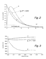
- H 2 O denotes the blank value of the measuring arrangement when the capillary is filled with water
- S g denotes a weighted sum signal of the intensity values T and S.
- the transmission detector 4 delivers a signal curve dependent on the concentration, which, similar to Lambert Beer's law, results in a continuous, monotonically falling measurement curve T.
- the scatter detector 5, supplies a measurement curve S which results from the superimposition of diffuse light scattering and absorption results. With increasing concentration of the sample ingredients the intensity value rises rapidly to a maximum at approx. 2-3 g / dl and falls then continuously with increasing concentration.
- the arrangement according to the invention is particularly suitable for measuring this problem in to get a grip.
- the concentration of the sample is above the Cross-section of the capillary viewed inhomogeneously.
- T of the transmission detector does this mean that the measured intensity increases because of the separation and the nonlinear characteristic curve the mean absorption decreases.
- the measurement signal decreases in the scattering channel because it is in the "thinner” part of the sample fewer scattering bodies are present and the absorption increases in the "denser" part.
- the two measurement signals T and S can be combined, for example, to form a weighted sum signal S g .
- the weighted sum signal for example human blood with a tHb of 5 g / dl
- the weighted sum signal has a constant value in a measurement window of approximately 20 s to 50 s, so that drift-free measurements at several wavelengths are possible.
- Another advantage given by this arrangement is that one can by selected weighting of the signals T and S a sum signal with different Sensitivity curve related to the concentration to be measured. This Property can be used particularly advantageously when measuring whole blood samples.
- tHb content 3 ⁇ tHb ⁇ 5 g / dl
- the measuring range can be reduced to lower concentrations by combining the signals can be expanded considerably without the problem of an ambiguous signal interpretation (Maximum of the scatter signal S).
- the transmission signal and the scatter signal for a special Specimen type e.g. human blood
- a special Specimen type e.g. human blood
- other types e.g. cattle blood
- the light-guiding mechanism in the scattering geometry is related to its behavior changed so significantly in the transmission geometry that a clear differentiation Rehearsal is possible.
- Other disturbances such as Dyes not in the Sample should be included are recognizable when the functional dependency of the two Measurement functions is changed sufficiently.
- the optical axis 5 ' lies of the second detector 5 parallel to the axis 3 'of the measuring radiation.
- the level ⁇ is in this Representation perpendicular to the image plane and coincides with the capillary axis 1 '.
- the capillary 1 is arranged in a bore 9 of a measuring block 10, which also receives the light guide 3 and the aperture 11 for the transmission detector 4 and the aperture 12 for the scattered light detector 5 are defined.
- a Optical separating element 13 is arranged, which the annular gap 14 between the capillary 1st and covers the bore 9.
- the optical separating element 13 can for example be an O-ring made of black rubber and arranged in a groove of the bore 9.
- the Separating element effectively prevents false light from being injected into the scattered light detector 5 and serves at the same time for centering the capillary 1 in the bore 9.
- the capillary 1 are fixed by sealing elements 15, which the capillary on the input and output side connect to inlet and outlet lines 16 and 17 for the sample medium.
- the mechanism of action can thereby be improved that the bore 9 of the measuring block 10 at least between the Coupling area 6 and coupling area 7 a diffusely reflecting surface 18 having. It turns out that such a surface design brings the best results because no preferred direction for the back reflection in the sample arises, which means one Execution less sensitive to local inhomogeneities than mirrored surfaces.
- the first detector 4 in Transmission geometry records changes in the intensity of the light source as well as coupling losses the measuring radiation when entering the capillary 1.
- the blank value measurement at second detector 5 in scattered light geometric gives additional information about changes inside the measuring capillary, for example dirt or deposits as well over the decoupling area of the capillary. Both blank measurements are preferred carried out synchronously in order to fluctuations in the intensity of the light source during the To compensate for reference measurement.
- the course of the measurement function of the scattered light detector 5 can be specific Requirements are adjusted. For example, the position of the maximum or Reversal point (see Fig. 2) so that this is below the expected minimum concentration of the sample to be measured is safe and thus ambiguous measurement results be avoided. Also the mean steepness or the steepness course over the interested Measuring range can be adapted and optimized within certain limits.
- the capillary 1 When measuring tHb and S02 in a whole blood sample, the capillary 1 typically points an inner diameter of approx. 1.1 to 1.6 mm and the distance a between the coupling area 6 and the decoupling area 7 is approximately 4 to 10 mm.
- the light guide 3 has a core diameter of approx. 1 mm, the aperture 11 or 12 is approx. 1.5 to 2.5 mm.
- Another advantage of the measurement function shown in FIG. 2 or its adaptation to the specific one Requirements is that the maximum intensity of the scattered radiation at a defined minimum sample concentration is reached and the entire dynamic measuring range the arrangement can be used for the entire concentration range. So that is also give the best use of the resolution achievable by the detection system. This is particularly advantageous if the medium to be measured is strongly absorbed, not diluted should be difficult or due to fluidic reasons difficult in a sufficiently thin Cell can be filled. This is especially true for biological fluid in particular Whole blood too.
- the intensity is plotted on the ordinate and the concentration in g / dl on the abscissa.
- 5 shows the course of the intensity of the transmission radiation (detector 4) for a capillary with an air gap (unmirrored) and for a mirrored capillary.
- 6 shows the intensity curve (amplified by a factor of 100) for the scattered light detector (detector 5) for both variants (mirrored and non-mirrored), the blank value (H 2 O mirrored or H 2 O non-mirrored) for one for both variants capillary filled with water is entered.
Landscapes
- Immunology (AREA)
- Pathology (AREA)
- Life Sciences & Earth Sciences (AREA)
- Chemical & Material Sciences (AREA)
- Analytical Chemistry (AREA)
- Biochemistry (AREA)
- Health & Medical Sciences (AREA)
- General Health & Medical Sciences (AREA)
- Physics & Mathematics (AREA)
- General Physics & Mathematics (AREA)
- Investigating Or Analysing Materials By Optical Means (AREA)
- Spectrometry And Color Measurement (AREA)
- Analysing Materials By The Use Of Radiation (AREA)
- Investigating Or Analysing Biological Materials (AREA)
- Measurement Of Radiation (AREA)
- Optical Measuring Cells (AREA)
Abstract
Description
- Fig. 1
- zeigt eine schematische Darstellung der erfindungsgemäßen Messanordnung zur Bestimmung der Transmissions- und der Streustrahlung einer flüssigen Proben,
- Fig. 2
- ein Diagramm des Intensitätsverlaufes bei steigender Konzentration eines Probeninhaltsstoffes für den Transmissions- und den Streulichtdetektor der Messanordnung,
- Fig. 3
- ein Diagramm, welches die Änderungen des Intensitätsverlaufes während der Messzeit zeigt,
- Fig. 4
- eine bevorzugte Ausführungsvariante der Erfindung, sowie die
- Fig. 5
- (Transmissionsstrahlung) und 6 (Streustrahlung) Diagramme über den Intensitätsverlauf bei steigender Konzentration eines Probeninhaltsstoffes.
Claims (6)
- Optische Messanordnung zur Bestimmung der Transmissions- und der Streustrahlung einer mit einer Messstrahlung beaufschlagten, in einer Kapillare (1) vorliegenden, flüssigen Probe, wobei die Achse (3')der Messstrahlung im wesentlichen senkrecht auf die Achse (1') der Kapillare (1) gerichtet ist, mit einem ersten Detektor (4) zur Erfassung der Transmissionsstrahlung, welcher im Bereich der Achse (3') der Messstrahlung angeordnet ist sowie mit einem in Richtung der Kapillarachse (1') mit einem Abstand (a) vom ersten Detektor (4) angeordneten zweiten Detektor (5) zur Erfassung der Streustrahlung, dadurch gekennzeichnet, daß der erste (4) und der zweite Detektor (5) auf unterschiedlichen Seiten einer Ebene (ε) liegen, welche die Kapillarachse (1') enthält und auf die Achse (3') der Messstrahlung normal steht.
- Messanordnung nach Anspruch 1, dadurch gekennzeichnet, daß die optische Achse (5') des zweiten Detektors (5) zur Achse (3') der Messstrahlung im wesentlichen parallel ausgerichtet ist.
- Messanordnung nach Anspruch 1 oder 2, dadurch gekennzeichnet, daß die in einer Bohrung (9) eines Messblockes (10) angeordnete Kapillare (1) zwischen einem Einkoppelbereich (6) für die Messstrahlung und einem Auskoppelbereich (7) für die Streustrahlung zumindest ein optisches Trennelement (13) aufweist, welches einen Ringspalt (14) zwischen der Kapillare (1) und der Bohrung (9) abdeckt.
- Messanordnung nach Anspruch 3, dadurch gekennzeichnet, daß das optische Trennelement (13) als O-Ring oder Quadring ausgeführt, welcher die Kapillare (1) in der Bohrung (9) des Messblockes (10) zentriert.
- Messanordnung nach Anspruch 3 oder 4, dadurch gekennzeichnet, daß die Bohrung (9) des Messblockes (10) zumindest zwischen dem Einkoppelbereich (6) für die Messstrahlung und dem Auskoppelbereich (7) für die Streustrahlung eine diffus reflektierende Oberfläche (18) aufweist.
- Messanordnung nach Anspruch 3 oder 4, dadurch gekennzeichnet, daß die Außenwand der Kapillare (1) mit Ausnahme des Einkoppelbereiches (6) für die Messstrahlung und des Auskoppelbereiches (7) für die Streustrahlung verspiegelt ist, oder eine dichroitische Beschichtung (8) aufweist.
Priority Applications (1)
| Application Number | Priority Date | Filing Date | Title |
|---|---|---|---|
| AT00890151T ATE232976T1 (de) | 1999-05-20 | 2000-05-11 | Optische messanordnung zur bestimmung der transmissions- und streustrahlung |
Applications Claiming Priority (2)
| Application Number | Priority Date | Filing Date | Title |
|---|---|---|---|
| AT0090099A AT406912B (de) | 1999-05-20 | 1999-05-20 | Optische messanordnung zur bestimmung der transmissions- und streustrahlung |
| AT90099 | 1999-05-20 |
Publications (3)
| Publication Number | Publication Date |
|---|---|
| EP1054252A2 true EP1054252A2 (de) | 2000-11-22 |
| EP1054252A3 EP1054252A3 (de) | 2001-07-18 |
| EP1054252B1 EP1054252B1 (de) | 2003-02-19 |
Family
ID=3502430
Family Applications (1)
| Application Number | Title | Priority Date | Filing Date |
|---|---|---|---|
| EP00890151A Expired - Lifetime EP1054252B1 (de) | 1999-05-20 | 2000-05-11 | Optische Messanordnung zur Bestimmung der Transmissions- und Streustrahlung |
Country Status (6)
| Country | Link |
|---|---|
| US (1) | US6388752B1 (de) |
| EP (1) | EP1054252B1 (de) |
| JP (1) | JP3318657B2 (de) |
| AT (2) | AT406912B (de) |
| DE (1) | DE50001263D1 (de) |
| ES (1) | ES2188497T3 (de) |
Cited By (2)
| Publication number | Priority date | Publication date | Assignee | Title |
|---|---|---|---|---|
| DE10360563A1 (de) * | 2003-12-22 | 2005-07-14 | BSH Bosch und Siemens Hausgeräte GmbH | Verfahren und Vorrichtung zur Bestimmung des Verunreinigungszustands von Flüssigkeiten |
| US7084646B2 (en) | 2003-08-07 | 2006-08-01 | Roche Diagnostics Operations, Inc. | Method of detecting a gas bubble in a liquid |
Families Citing this family (10)
| Publication number | Priority date | Publication date | Assignee | Title |
|---|---|---|---|---|
| US6794671B2 (en) * | 2002-07-17 | 2004-09-21 | Particle Sizing Systems, Inc. | Sensors and methods for high-sensitivity optical particle counting and sizing |
| DE60312737T2 (de) * | 2002-12-20 | 2007-12-06 | Optoq Ab | Verfahren und Vorrichtung zur Messung von Blutbestandteilen |
| US7502114B2 (en) * | 2004-03-12 | 2009-03-10 | Mks Instruments, Inc. | Ozone concentration sensor |
| US8262992B2 (en) * | 2007-11-13 | 2012-09-11 | Roche Diagnostics Operations, Inc. | Modular sensor cassette |
| DE102013018284B4 (de) * | 2013-10-31 | 2015-08-27 | Fresenius Medical Care Deutschland Gmbh | Verfahren und Vorrichtung zur Erfassung der Hämolyse oder zur Bestimmung eines den Einfluss der Hämolyse auf eine Messung des Hämatokrits korrigierenden Korrekturfaktors |
| DE102014000651B3 (de) * | 2014-01-17 | 2015-05-13 | Gottfried Wilhelm Leibniz Universität Hannover | Vorrichtung zum Bestimmen einer Konzentration eines chemischen Stoffes |
| US11187661B2 (en) * | 2017-07-05 | 2021-11-30 | Saudi Arabian Oil Company | Detecting black powder levels in flow-lines |
| CN107831143B (zh) * | 2017-12-05 | 2020-06-09 | 西人马联合测控(泉州)科技有限公司 | 一种流体透明度检测装置和检测方法 |
| US20230251179A1 (en) * | 2022-02-09 | 2023-08-10 | The Wave Talk, Inc. | Turbidity monitoring apparatus |
| WO2026015587A1 (en) * | 2024-07-09 | 2026-01-15 | Wyatt Technology, Llc | Inline light detection system for nanoparticle analysis |
Family Cites Families (9)
| Publication number | Priority date | Publication date | Assignee | Title |
|---|---|---|---|---|
| DE2625088A1 (de) * | 1976-06-04 | 1977-12-15 | Bbc Brown Boveri & Cie | Optoelektronische vorrichtung |
| US4745279A (en) | 1986-01-02 | 1988-05-17 | American Hospital Supply Corporation | Hematocrit measuring apparatus |
| US5241368A (en) * | 1991-01-07 | 1993-08-31 | Custom Sample Systems, Inc. | Fiber-optic probe for absorbance and turbidity measurement |
| US5331958A (en) | 1992-03-31 | 1994-07-26 | University Of Manitoba | Spectrophotometric blood analysis |
| US5601080A (en) | 1994-12-28 | 1997-02-11 | Coretech Medical Technologies Corporation | Spectrophotometric blood analysis |
| US5828458A (en) * | 1995-01-26 | 1998-10-27 | Nartron Corporation | Turbidity sensor |
| AT403412B (de) | 1996-04-02 | 1998-02-25 | Avl Verbrennungskraft Messtech | Vorrichtung und verfahren zur bestimmung der konzentration von hämoglobinderivaten in einer unverdünnten, unhämolysierten vollblutprobe |
| US5781284A (en) * | 1996-04-24 | 1998-07-14 | Infante; David A. | System for detecting impurities contained in a fluid medium |
| US6076049A (en) * | 1998-02-26 | 2000-06-13 | Premier Instruments, Inc. | Narrow band infrared water cut meter |
-
1999
- 1999-05-20 AT AT0090099A patent/AT406912B/de not_active IP Right Cessation
-
2000
- 2000-05-11 DE DE50001263T patent/DE50001263D1/de not_active Expired - Lifetime
- 2000-05-11 EP EP00890151A patent/EP1054252B1/de not_active Expired - Lifetime
- 2000-05-11 AT AT00890151T patent/ATE232976T1/de not_active IP Right Cessation
- 2000-05-11 ES ES00890151T patent/ES2188497T3/es not_active Expired - Lifetime
- 2000-05-17 US US09/572,594 patent/US6388752B1/en not_active Expired - Lifetime
- 2000-05-18 JP JP2000145786A patent/JP3318657B2/ja not_active Expired - Fee Related
Cited By (2)
| Publication number | Priority date | Publication date | Assignee | Title |
|---|---|---|---|---|
| US7084646B2 (en) | 2003-08-07 | 2006-08-01 | Roche Diagnostics Operations, Inc. | Method of detecting a gas bubble in a liquid |
| DE10360563A1 (de) * | 2003-12-22 | 2005-07-14 | BSH Bosch und Siemens Hausgeräte GmbH | Verfahren und Vorrichtung zur Bestimmung des Verunreinigungszustands von Flüssigkeiten |
Also Published As
| Publication number | Publication date |
|---|---|
| DE50001263D1 (de) | 2003-03-27 |
| US6388752B1 (en) | 2002-05-14 |
| ATA90099A (de) | 2000-02-15 |
| ES2188497T3 (es) | 2003-07-01 |
| EP1054252B1 (de) | 2003-02-19 |
| JP2000356582A (ja) | 2000-12-26 |
| EP1054252A3 (de) | 2001-07-18 |
| ATE232976T1 (de) | 2003-03-15 |
| AT406912B (de) | 2000-10-25 |
| JP3318657B2 (ja) | 2002-08-26 |
Similar Documents
| Publication | Publication Date | Title |
|---|---|---|
| DE3103476C2 (de) | ||
| EP2032967B1 (de) | Spektroskopischer detektor und verfahren zur bestimmung von blut und biologischen markersubstanzen in flüssigkeiten | |
| DE3876321T2 (de) | Kopf zur messung des reflexionsvermoegens von entfernten proben. | |
| AT404513B (de) | Verfahren und messanordnung zur optischen bestimmung der totalen hämoglobinkonzentration | |
| DE60212444T2 (de) | Verfahren zur quantitativen hämoglobinbestimmung in unverdünntem nichthämolysiertem vollblut | |
| DE69331188T2 (de) | Vorrichtung und verfahren zur molekularen charakterisierung | |
| DE69222535T2 (de) | Nachweis von molekularen veränderungen der augenlinse | |
| DE60312737T2 (de) | Verfahren und Vorrichtung zur Messung von Blutbestandteilen | |
| EP0148497B1 (de) | Vorrichtung zum Führen und Sammeln von Licht in der Fotometrie od. dgl. | |
| EP0800074B1 (de) | Vorrichtung und Verwendung einer Vorrichtung zur Bestimmung der Konzentration von Hämoglobinderivaten in einer unverdünnten, unhämolysierten Vollblutprobe | |
| DE112009002702B4 (de) | Automatischer Analysator | |
| DE69016027T2 (de) | Optischer Lesekopf für eine Immunoassay Vorrichtung. | |
| WO2007090378A2 (de) | Messvorrichtung zur bestimmung der grösse, grössenverteilung und menge von partikeln im nanoskopischen bereich | |
| WO1997027469A1 (de) | Verfahren und vorrichtung zur bestimmung eines analyten in einer streuenden matrix | |
| EP3051272A2 (de) | Verfahren zur bestimmung von lipiden und anderen störsubstanzen in körperflüssigkeitsproben | |
| EP0938658A1 (de) | Verfahren und vorrichtung zur kombinierten absorptions- und reflektanzspektroskopie | |
| DE4417639A1 (de) | Verfahren zur Bestimmung eines Analyten in einer biologischen Probe | |
| EP1054252B1 (de) | Optische Messanordnung zur Bestimmung der Transmissions- und Streustrahlung | |
| DE60032853T2 (de) | Verfahren zur Messung der Konzentration einer Lösung | |
| EP1183524B1 (de) | Messung von trübungen mittels reflektometrie | |
| EP3591378B1 (de) | Verfahren zur bestimmung von lipiden, hämoglobin und bilirubin in körperflüssigkeitsproben | |
| DE69636211T2 (de) | Verfahren für die optische Messung einer Flüssigkeit in einem porösen Material | |
| DE102011012674B3 (de) | Verfahren und Nachweisvorrichtung zur Bestimmung eines Nierenfunktionsparameters | |
| DE10321356A1 (de) | Verfahren zur reflexions-polarimetrischen Bestimmung der Konzentration optisch aktiver Bestandteile in Medien sowie eine Vorrichtung zur Durchführung dieses Verfahrens | |
| DE19647222C1 (de) | Verfahren und Vorrichtung zur kombinierten Absorptions- und Remissionsspektroskopie für die Ermittlung der Absorptions-, Streu- und Fluoreszenzfähigkeit transmittierender Flüssigkeiten, Gase und Festkörper |
Legal Events
| Date | Code | Title | Description |
|---|---|---|---|
| PUAI | Public reference made under article 153(3) epc to a published international application that has entered the european phase |
Free format text: ORIGINAL CODE: 0009012 |
|
| AK | Designated contracting states |
Kind code of ref document: A2 Designated state(s): AT BE CH CY DE DK ES FI FR GB GR IE IT LI LU MC NL PT SE |
|
| AX | Request for extension of the european patent |
Free format text: AL;LT;LV;MK;RO;SI |
|
| PUAL | Search report despatched |
Free format text: ORIGINAL CODE: 0009013 |
|
| AK | Designated contracting states |
Kind code of ref document: A3 Designated state(s): AT BE CH CY DE DK ES FI FR GB GR IE IT LI LU MC NL PT SE |
|
| AX | Request for extension of the european patent |
Free format text: AL;LT;LV;MK;RO;SI |
|
| 17P | Request for examination filed |
Effective date: 20010817 |
|
| RAP1 | Party data changed (applicant data changed or rights of an application transferred) |
Owner name: F.HOFFMANN-LA ROCHE AG |
|
| 17Q | First examination report despatched |
Effective date: 20020220 |
|
| AKX | Designation fees paid |
Free format text: AT BE CH CY DE DK ES FI FR GB GR IE IT LI LU MC NL PT SE |
|
| GRAH | Despatch of communication of intention to grant a patent |
Free format text: ORIGINAL CODE: EPIDOS IGRA |
|
| GRAH | Despatch of communication of intention to grant a patent |
Free format text: ORIGINAL CODE: EPIDOS IGRA |
|
| GRAA | (expected) grant |
Free format text: ORIGINAL CODE: 0009210 |
|
| AK | Designated contracting states |
Designated state(s): AT BE CH CY DE DK ES FI FR GB GR IE IT LI LU MC NL PT SE |
|
| PG25 | Lapsed in a contracting state [announced via postgrant information from national office to epo] |
Ref country code: GR Free format text: LAPSE BECAUSE OF FAILURE TO SUBMIT A TRANSLATION OF THE DESCRIPTION OR TO PAY THE FEE WITHIN THE PRESCRIBED TIME-LIMIT Effective date: 20030219 Ref country code: FI Free format text: LAPSE BECAUSE OF FAILURE TO SUBMIT A TRANSLATION OF THE DESCRIPTION OR TO PAY THE FEE WITHIN THE PRESCRIBED TIME-LIMIT Effective date: 20030219 Ref country code: NL Free format text: LAPSE BECAUSE OF FAILURE TO SUBMIT A TRANSLATION OF THE DESCRIPTION OR TO PAY THE FEE WITHIN THE PRESCRIBED TIME-LIMIT Effective date: 20030219 Ref country code: IE Free format text: LAPSE BECAUSE OF FAILURE TO SUBMIT A TRANSLATION OF THE DESCRIPTION OR TO PAY THE FEE WITHIN THE PRESCRIBED TIME-LIMIT Effective date: 20030219 |
|
| REG | Reference to a national code |
Ref country code: GB Ref legal event code: FG4D Free format text: NOT ENGLISH |
|
| REG | Reference to a national code |
Ref country code: CH Ref legal event code: EP |
|
| REG | Reference to a national code |
Ref country code: IE Ref legal event code: FG4D Free format text: GERMAN |
|
| REF | Corresponds to: |
Ref document number: 50001263 Country of ref document: DE Date of ref document: 20030327 Kind code of ref document: P |
|
| PG25 | Lapsed in a contracting state [announced via postgrant information from national office to epo] |
Ref country code: CY Free format text: LAPSE BECAUSE OF FAILURE TO SUBMIT A TRANSLATION OF THE DESCRIPTION OR TO PAY THE FEE WITHIN THE PRESCRIBED TIME-LIMIT Effective date: 20030511 Ref country code: LU Free format text: LAPSE BECAUSE OF NON-PAYMENT OF DUE FEES Effective date: 20030511 |
|
| PG25 | Lapsed in a contracting state [announced via postgrant information from national office to epo] |
Ref country code: PT Free format text: LAPSE BECAUSE OF FAILURE TO SUBMIT A TRANSLATION OF THE DESCRIPTION OR TO PAY THE FEE WITHIN THE PRESCRIBED TIME-LIMIT Effective date: 20030519 Ref country code: SE Free format text: LAPSE BECAUSE OF FAILURE TO SUBMIT A TRANSLATION OF THE DESCRIPTION OR TO PAY THE FEE WITHIN THE PRESCRIBED TIME-LIMIT Effective date: 20030519 Ref country code: DK Free format text: LAPSE BECAUSE OF FAILURE TO SUBMIT A TRANSLATION OF THE DESCRIPTION OR TO PAY THE FEE WITHIN THE PRESCRIBED TIME-LIMIT Effective date: 20030519 |
|
| PG25 | Lapsed in a contracting state [announced via postgrant information from national office to epo] |
Ref country code: MC Free format text: LAPSE BECAUSE OF NON-PAYMENT OF DUE FEES Effective date: 20030531 Ref country code: BE Free format text: LAPSE BECAUSE OF NON-PAYMENT OF DUE FEES Effective date: 20030531 |
|
| GBT | Gb: translation of ep patent filed (gb section 77(6)(a)/1977) |
Effective date: 20030515 |
|
| REG | Reference to a national code |
Ref country code: ES Ref legal event code: FG2A Ref document number: 2188497 Country of ref document: ES Kind code of ref document: T3 |
|
| NLV1 | Nl: lapsed or annulled due to failure to fulfill the requirements of art. 29p and 29m of the patents act | ||
| ET | Fr: translation filed | ||
| REG | Reference to a national code |
Ref country code: IE Ref legal event code: FD4D Ref document number: 1054252E Country of ref document: IE |
|
| BERE | Be: lapsed |
Owner name: F. *HOFFMANN-LA ROCHE A.G. Effective date: 20030531 |
|
| PLBE | No opposition filed within time limit |
Free format text: ORIGINAL CODE: 0009261 |
|
| STAA | Information on the status of an ep patent application or granted ep patent |
Free format text: STATUS: NO OPPOSITION FILED WITHIN TIME LIMIT |
|
| 26N | No opposition filed |
Effective date: 20031120 |
|
| PGFP | Annual fee paid to national office [announced via postgrant information from national office to epo] |
Ref country code: AT Payment date: 20040512 Year of fee payment: 5 |
|
| PGFP | Annual fee paid to national office [announced via postgrant information from national office to epo] |
Ref country code: CH Payment date: 20040517 Year of fee payment: 5 |
|
| PG25 | Lapsed in a contracting state [announced via postgrant information from national office to epo] |
Ref country code: AT Free format text: LAPSE BECAUSE OF NON-PAYMENT OF DUE FEES Effective date: 20050511 |
|
| PG25 | Lapsed in a contracting state [announced via postgrant information from national office to epo] |
Ref country code: CH Free format text: LAPSE BECAUSE OF NON-PAYMENT OF DUE FEES Effective date: 20050531 Ref country code: LI Free format text: LAPSE BECAUSE OF NON-PAYMENT OF DUE FEES Effective date: 20050531 |
|
| REG | Reference to a national code |
Ref country code: CH Ref legal event code: PL |
|
| PGFP | Annual fee paid to national office [announced via postgrant information from national office to epo] |
Ref country code: GB Payment date: 20140425 Year of fee payment: 15 |
|
| PGFP | Annual fee paid to national office [announced via postgrant information from national office to epo] |
Ref country code: IT Payment date: 20140519 Year of fee payment: 15 Ref country code: ES Payment date: 20140523 Year of fee payment: 15 Ref country code: DE Payment date: 20140602 Year of fee payment: 15 Ref country code: FR Payment date: 20140424 Year of fee payment: 15 |
|
| REG | Reference to a national code |
Ref country code: DE Ref legal event code: R119 Ref document number: 50001263 Country of ref document: DE |
|
| GBPC | Gb: european patent ceased through non-payment of renewal fee |
Effective date: 20150511 |
|
| PG25 | Lapsed in a contracting state [announced via postgrant information from national office to epo] |
Ref country code: IT Free format text: LAPSE BECAUSE OF NON-PAYMENT OF DUE FEES Effective date: 20150511 |
|
| REG | Reference to a national code |
Ref country code: FR Ref legal event code: ST Effective date: 20160129 |
|
| PG25 | Lapsed in a contracting state [announced via postgrant information from national office to epo] |
Ref country code: GB Free format text: LAPSE BECAUSE OF NON-PAYMENT OF DUE FEES Effective date: 20150511 Ref country code: DE Free format text: LAPSE BECAUSE OF NON-PAYMENT OF DUE FEES Effective date: 20151201 |
|
| PG25 | Lapsed in a contracting state [announced via postgrant information from national office to epo] |
Ref country code: FR Free format text: LAPSE BECAUSE OF NON-PAYMENT OF DUE FEES Effective date: 20150601 |
|
| REG | Reference to a national code |
Ref country code: ES Ref legal event code: FD2A Effective date: 20160630 |
|
| PG25 | Lapsed in a contracting state [announced via postgrant information from national office to epo] |
Ref country code: ES Free format text: LAPSE BECAUSE OF NON-PAYMENT OF DUE FEES Effective date: 20150512 |