EP1054253A2 - Dispositif pour mesurer l'humidité à l'intérieur d'un camion - Google Patents
Dispositif pour mesurer l'humidité à l'intérieur d'un camion Download PDFInfo
- Publication number
- EP1054253A2 EP1054253A2 EP00108069A EP00108069A EP1054253A2 EP 1054253 A2 EP1054253 A2 EP 1054253A2 EP 00108069 A EP00108069 A EP 00108069A EP 00108069 A EP00108069 A EP 00108069A EP 1054253 A2 EP1054253 A2 EP 1054253A2
- Authority
- EP
- European Patent Office
- Prior art keywords
- microwave
- measuring device
- moisture measuring
- moisture
- unit
- Prior art date
- Legal status (The legal status is an assumption and is not a legal conclusion. Google has not performed a legal analysis and makes no representation as to the accuracy of the status listed.)
- Ceased
Links
- 230000005855 radiation Effects 0.000 claims abstract description 26
- XLYOFNOQVPJJNP-UHFFFAOYSA-N water Substances O XLYOFNOQVPJJNP-UHFFFAOYSA-N 0.000 claims abstract description 21
- 238000010521 absorption reaction Methods 0.000 claims abstract description 17
- 238000011156 evaluation Methods 0.000 claims description 14
- 230000003287 optical effect Effects 0.000 claims description 7
- 239000002184 metal Substances 0.000 claims description 3
- 238000005259 measurement Methods 0.000 abstract description 8
- 230000005540 biological transmission Effects 0.000 abstract description 4
- 238000012360 testing method Methods 0.000 description 4
- 230000035515 penetration Effects 0.000 description 3
- 238000002835 absorbance Methods 0.000 description 2
- 238000004519 manufacturing process Methods 0.000 description 2
- 239000000463 material Substances 0.000 description 2
- 230000002745 absorbent Effects 0.000 description 1
- 239000002250 absorbent Substances 0.000 description 1
- 238000009825 accumulation Methods 0.000 description 1
- 238000005253 cladding Methods 0.000 description 1
- 238000010276 construction Methods 0.000 description 1
- 230000001066 destructive effect Effects 0.000 description 1
- 238000001514 detection method Methods 0.000 description 1
- 230000000694 effects Effects 0.000 description 1
- 239000004744 fabric Substances 0.000 description 1
- 230000010354 integration Effects 0.000 description 1
- 230000003993 interaction Effects 0.000 description 1
- 238000009659 non-destructive testing Methods 0.000 description 1
- 239000002689 soil Substances 0.000 description 1
- 230000001960 triggered effect Effects 0.000 description 1
- 230000000007 visual effect Effects 0.000 description 1
Images
Classifications
-
- G—PHYSICS
- G01—MEASURING; TESTING
- G01N—INVESTIGATING OR ANALYSING MATERIALS BY DETERMINING THEIR CHEMICAL OR PHYSICAL PROPERTIES
- G01N22/00—Investigating or analysing materials by the use of microwaves or radio waves, i.e. electromagnetic waves with a wavelength of one millimetre or more
- G01N22/04—Investigating moisture content
Definitions
- the present invention relates to a moisture measuring device for the interior of a motor vehicle, comprising at least one microwave transmitter unit and at least one microwave receiving unit, the frequency of the used Microwaves in the range of the microwave absorption frequencies of water and the moisture-related absorption of microwave radiation between the minimum a microwave transmission unit and the at least one microwave reception unit can be determined by the moisture measuring device.
- a quality criterion in vehicle production is the tightness of the vehicles towards water. Under normal operating conditions, no water is allowed in the Interior, that is, into the passenger compartment or trunk. For Ensuring this quality goal, the vehicles are intensified in a test room sprinkled with water and then checked. The first step is to find a visual Control instead of looking for penetrated moisture on surfaces. Moisture that has got under cladding or carpeting is all in one second step detected with the help of so-called penetration sensors. Invaders Depending on the point of entry, moisture can collect in different places. The spot depends essentially on the place of entry, the amount of water, the test duration and the Time between sprinkling and search. Also plays the nature of the Surrounding media plays a role, for example an absorbent slows down Carpeting the rate of penetration of moisture. Therefore, in practice, there are several places after moisture accumulation examined.
- the penetration sensors mentioned above are essentially two Electrodes, which are in significant places, for example through the carpet be pushed.
- the moisture can be measured by changing the resistance or conductance between the electrodes.
- a moisture measuring device of the type mentioned is known from US Pat. No. 4,674 325 known.
- a device is described which, for example, the Can determine moisture content of paper during manufacture. The paper will thereby between a microwave transmitter unit and a microwave receiver unit passed and a continuous measurement of the moisture content through the Absorption of microwave radiation is carried out.
- both devices are for use in measuring moisture in the Unsuitable vehicle interior, as it detects moisture, among other things must be, which as a water film below the actual fabric or carpet can be present.
- the device of U.S. Patent 4,674,325 can be used for this purpose also not be used because the test material at least between the Microwave transmitter and microwave receiver must be arranged, which is For example, prove to be difficult with a carpeted floor or would be prevented by the floor panel.
- the problem underlying the invention is a moisture measuring device to provide the type mentioned above, which is easy to handle and equally allows a non-destructive testing of the moisture content.
- this problem is solved in that the at least one Microwave transmitter unit and the at least one microwave receiver unit so in the Moisture measuring device are arranged that that of the at least one Microwave transmitter unit emitting microwave radiation after reflection on the Microwave radiation of the frequency used is at least partially reflective Body component of the motor vehicle from the at least one Microwave receiving unit can be detected.
- the special boundary conditions in particular the vehicle sheets as reflection surfaces, exploited to provide a non-destructive and easy way to detect Provide moisture in the vehicle interior.
- the use of the existing Vehicle sheets as reflective surfaces also favor the compact design, because Microwave transmitter unit and microwave receiver unit combined in one component can be.
- Another advantageous embodiment of the invention results from the use a microwave radiation with a frequency of approx. 10 GHz.
- a microwave radiation with a frequency of approx. 10 GHz.
- For the detection of Moisture will weaken the microwave radiation as it passes through determined by the material to be measured.
- By interaction between the Microwave radiation and the water molecules take place especially for Microwave frequencies in the area of the strong absorption band of water at about 10 GHz a strong attenuation of the microwave radiation.
- the measurement signal is already around 73% weakened, which means optimal measuring accuracy.
- Another advantageous embodiment of the invention is a compact Provide housing for the moisture measuring arrangement. This will make it easy Manageability and flexible application guaranteed.
- the main measurement parameters can be stored in simple form and the operator can essentially focus on the correct positioning of the moisture measuring arrangement.
- the Absorbance can be read easily. Furthermore, changes can occur relatively unproblematic with regard to the moisture content or moisture areas be narrowed down.
- the user is still supported by an optical and / or acoustic Warning device which is based on a threshold value regarding the degree of absorption can be adjusted.
- the user is thus not forced to use the display instrument constantly read and can focus on the alignment of the measuring arrangement focus.
- the combination of evaluation electronics has proven to be particularly advantageous, Control electronics, battery pack, display to visualize the degree of absorption and optical / acoustic warning device in a compact, cylindrical housing.
- the measuring arrangement can thus be used completely independently and without annoying wiring are made possible, in particular for use in areas that are difficult to access becomes.
- a space-saving Arrangement By using a transmitter / receiver combination, a space-saving Arrangement provided, which at the same time a defined distance between Guaranteed microwave source and microwave sink. Choosing a defined one Distance is quite useful since the reception of the microwave radiation below the reproducibility of the measurement results at a certain angle of reflection guaranteed.
- the function of the measuring device is also through the use of a Shielding in the measuring direction of the transmitter / receiver combination favors.
- a Shielding prevents microwave radiation from escaping to the side one could falsify the result and secondly endanger the user could.
- a suitable shielding a defined measuring area is created created.
- a hollow shield has proven to be particularly advantageous Hemisphere, similar to a flashlight reflector, proved to be made of a metal there is that microwave radiation can reflect and a in its pole Passage opening for and from the transmitter / receiver combination has incoming microwave radiation. This measure will, in addition to a optimal shielding, another advantage achieved.
- Soil geometries are no longer directly in the direction of the microwaves Microwave receiver unit reflected. If you use a shield housing reflective metal, the microwave is emitted indirectly through the shield reflected to the microwave receiving unit. The shield housing can Focus reflected radiation onto the microwave receiver unit.
- the use of one or more additional microwave transmitting and / or receiving units an additional potential Measurement inaccuracy can be hidden. Indicates the surface to be examined Differences in height by an odd multiple of half the wavelength of the Microwave on, so interference can weaken the received measurement signal and falsify the result.
- the effect can be influenced by using several preferably overlapping partial measuring ranges can be reduced.
- the partial measuring ranges can, for example, by using two or more Microwave transmitter units are generated.
- the measuring surfaces of the individual Microwave transmitter units are smaller than the entire measuring area and result in the Total area.
- the Microwave transmitter units are triggered and evaluated at different times. Interference due to height differences only affect some of the Partial measuring ranges, whereby the distinction between height difference and Moisture and the basis of a detailed analysis is given.
- the evaluation of all received signals leads to an increase in security compared to one Misinterpretation.
- the Support surface of the shield electrodes may be provided.
- the Measuring principle can not be determined whether the water is above or below the Carpet is located. However, water can flow between the electrodes through the electrodes Surface of the carpet and the shielding housing. This The evaluation electronics can issue information with a corresponding warning.
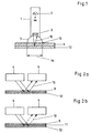
- a moisture measuring device can be essentially one cylindrical housing 1 and a transmitter / receiver combination 2 for microwaves comprising a microwave beam of a suitable frequency, for example 10 GHz, in the direction of a test object, for example a carpet 9, emit and can detect the reflected microwave radiation.
- a suitable frequency for example 10 GHz
- Shield 3 is provided below the transmitter / receiver combination 2, which the Can have the shape of a hollow hemisphere and in its pole an opening for has the microwave radiation 10. In the operating state it is the pole opposite opening of the shield 3 on the object to be analyzed directed, or the circular edge of the shield 3 touches the object.
- Reference number 14 denotes the measurable measuring range in FIG. 1.
- the housing 1 as such can be evaluation electronics, evaluation control and include a battery pack. Furthermore, a display 7 for displaying the Absorbance and an optical and acoustic warning device 8 installed his.
- the construction as well as the integration of everything needed to measure the moisture Components allow a very compact design of the Moisture measuring device, which is an unproblematic measurement of moisture for example on carpets 9 in relatively difficult to access places in Allows vehicle interior.
- the microwave radiation 10 from a transmission unit 4 is Transmitter / receiver combination 2 towards the carpet 9 and one below arranged floor plate 12 emitted.
- 2a is no water film 11 or Moisture present in the carpeting 9
- the microwave radiation 10 is through the bottom plate 12 to the microwave receiving unit 5 without great losses Sender / receiver combination 2 reflected back.
- the evaluation electronics measures that Degree of absorption and shows this on the display 7 to show the Absorption level.
- the presented measuring principle can not determine whether the water is above or are located below the carpet, are also on the contact surface of the Shielding 3 electrodes 13 arranged which water between the surface of the Carpet and the shielding housing. This information will also forwarded to the evaluation electronics, evaluated accordingly and displayed.
- the evaluation electronics can be set so that from one a certain, predefined degree of absorption an optical and / or acoustic Warning is issued.
Landscapes
- Physics & Mathematics (AREA)
- Biochemistry (AREA)
- Health & Medical Sciences (AREA)
- Life Sciences & Earth Sciences (AREA)
- Chemical & Material Sciences (AREA)
- Analytical Chemistry (AREA)
- Electromagnetism (AREA)
- General Health & Medical Sciences (AREA)
- General Physics & Mathematics (AREA)
- Immunology (AREA)
- Pathology (AREA)
- Investigating Or Analysing Materials By Optical Means (AREA)
- Investigating Or Analyzing Materials By The Use Of Electric Means (AREA)
Applications Claiming Priority (2)
| Application Number | Priority Date | Filing Date | Title |
|---|---|---|---|
| DE1999123497 DE19923497A1 (de) | 1999-05-21 | 1999-05-21 | Feuchtigkeitsmeßvorrichtung für den Innenraum eines Kraftfahrzeugs |
| DE19923497 | 1999-05-21 |
Publications (2)
| Publication Number | Publication Date |
|---|---|
| EP1054253A2 true EP1054253A2 (fr) | 2000-11-22 |
| EP1054253A3 EP1054253A3 (fr) | 2003-03-26 |
Family
ID=7908845
Family Applications (1)
| Application Number | Title | Priority Date | Filing Date |
|---|---|---|---|
| EP00108069A Ceased EP1054253A3 (fr) | 1999-05-21 | 2000-04-25 | Dispositif pour mesurer l'humidité à l'intérieur d'un camion |
Country Status (2)
| Country | Link |
|---|---|
| EP (1) | EP1054253A3 (fr) |
| DE (1) | DE19923497A1 (fr) |
Cited By (1)
| Publication number | Priority date | Publication date | Assignee | Title |
|---|---|---|---|---|
| WO2020192318A1 (fr) * | 2019-03-26 | 2020-10-01 | 京东方科技集团股份有限公司 | Procédé et appareil de détection d'humidité ambiante |
Family Cites Families (7)
| Publication number | Priority date | Publication date | Assignee | Title |
|---|---|---|---|---|
| DE1238243B (de) * | 1957-03-06 | 1967-04-06 | Beloit Iron Works | Anordnung zum Feuchtemessen an festen Materialien |
| JPS6063039A (ja) * | 1983-09-19 | 1985-04-11 | 株式会社肌粧品科学開放研究所 | 皮膚等の水分測定装置 |
| JPS60135752A (ja) * | 1983-12-23 | 1985-07-19 | Yokogawa Hokushin Electric Corp | マイクロ波水分計 |
| US5497100A (en) * | 1994-10-17 | 1996-03-05 | Hughes Aircraft Company | Surface condition sensing system |
| DE19608535A1 (de) * | 1996-03-06 | 1997-09-11 | Tobias Kippenberg | Vorrichtung zum Erkennen von auf der Straße befindlichem Eis |
| DE29617488U1 (de) * | 1996-10-08 | 1997-05-15 | pro/M/tec Theisen GmbH, 76332 Bad Herrenalb | Mikrowellen-Tauch-Sensor |
| DE19815062C2 (de) * | 1998-04-03 | 2000-01-13 | Optron Messtechnik Gmbh | Verfahren zur Detektion von Feuchtigkeit bei einer Dichtheitsprüfung von Kraftfahrzeugen |
-
1999
- 1999-05-21 DE DE1999123497 patent/DE19923497A1/de not_active Withdrawn
-
2000
- 2000-04-25 EP EP00108069A patent/EP1054253A3/fr not_active Ceased
Cited By (1)
| Publication number | Priority date | Publication date | Assignee | Title |
|---|---|---|---|---|
| WO2020192318A1 (fr) * | 2019-03-26 | 2020-10-01 | 京东方科技集团股份有限公司 | Procédé et appareil de détection d'humidité ambiante |
Also Published As
| Publication number | Publication date |
|---|---|
| EP1054253A3 (fr) | 2003-03-26 |
| DE19923497A1 (de) | 2000-11-23 |
Similar Documents
| Publication | Publication Date | Title |
|---|---|---|
| EP0761585B1 (fr) | Détecteur de fil | |
| EP3443297B1 (fr) | Dispositif de mesure térahertz pour la mesure d'objets à contrôler et procédé de mesure térahertz | |
| EP1747483B1 (fr) | Appareil de reperage et procede pour calibrer un appareil de reperage | |
| DE4341080C1 (de) | Lichtelektrische Vorrichtung mit einem Testobjekt | |
| EP4172559B1 (fr) | Dispositif de mesure de thz et procédé de mesure de thz pour la mesure d'objets à tester, en particulier des tuyaux | |
| EP0209860A2 (fr) | Appareil de mesure de la réflexion pour mesure sans contact | |
| WO2003055382A2 (fr) | Procede et dispositif de determination d'un parametre de transport de lumiere dans une matrice biologique | |
| EP2479586B1 (fr) | Procédé destiné à l'évaluation d'un degré d'impureté d'un disque frontal d'un dispositif de saisie optique et dispositif de saisie optique | |
| DE10222797C5 (de) | Abstandsbestimmung | |
| EP1051613B1 (fr) | Dispositif pour le controle par ultrasons d'articles en forme de feuilles | |
| DE102013002859B4 (de) | Vorrichtung zur Detektion von Rauch in einem Raum und Verfahren zum Überprüfen der Funktionsfähigkeit einer derartigen Vorrichtung | |
| DE112007000959B4 (de) | Detektieren der Position einer Kante einer Bahn | |
| DE2714397A1 (de) | Verfahren und vorrichtung fuer messungen an duennen filmen mit spiegelnden oberflaechen unter verwendung von infrarotstrahlung | |
| EP0344645A2 (fr) | Appareil de mesure de réflexion | |
| DE2643126A1 (de) | Einrichtung zur untersuchung von objekten nach dem reflexionsprinzip | |
| DE1466101B1 (de) | Reflexionsarme Kammer zur Untersuchung und Bewertung von Mikrowellengeraeten | |
| DE19962949A1 (de) | Vorrichtung zur abtaststrahlungsbasierten Oberflächenzustandserkennung insbesondere von Straßen | |
| DE10041182C2 (de) | Optoelektronische Vorrichtung | |
| EP0550542B1 (fr) | Dispositif pour la determination qualitative et/ou quantitative de la composition d'un echantillon a analyser | |
| EP1054253A2 (fr) | Dispositif pour mesurer l'humidité à l'intérieur d'un camion | |
| DE102004038239A1 (de) | Luftfeder mit integrierter optischer Höhenstandssensorik | |
| EP1763653B1 (fr) | Procede et dispositif de determination de l'epaisseur de materiaux a base de hautes frequences | |
| EP0169444A2 (fr) | Sonde de la rugosité | |
| DE2116782C3 (de) | Verfahren und Vorrichtung zur Bestimmung des Volumens pro Längeneinheit von fadenförmigen Erzeugnissen der Textilindustrie | |
| DE19519051A1 (de) | Verfahren und Vorrichtung zur polarimetrischen Bestimmung der Blutzuckerkonzentration |
Legal Events
| Date | Code | Title | Description |
|---|---|---|---|
| PUAI | Public reference made under article 153(3) epc to a published international application that has entered the european phase |
Free format text: ORIGINAL CODE: 0009012 |
|
| AK | Designated contracting states |
Kind code of ref document: A2 Designated state(s): AT BE CH CY DE DK ES FI FR GB GR IE IT LI LU MC NL PT SE |
|
| AX | Request for extension of the european patent |
Free format text: AL;LT;LV;MK;RO;SI |
|
| PUAL | Search report despatched |
Free format text: ORIGINAL CODE: 0009013 |
|
| AK | Designated contracting states |
Kind code of ref document: A3 Designated state(s): AT BE CH CY DE DK ES FI FR GB GR IE IT LI LU MC NL PT SE Designated state(s): AT BE CH CY DE DK ES FI FR GB GR IE IT LI LU MC NL PT SE |
|
| AX | Request for extension of the european patent |
Extension state: AL LT LV MK RO SI |
|
| 17P | Request for examination filed |
Effective date: 20030926 |
|
| AKX | Designation fees paid |
Designated state(s): AT BE CH CY DE DK ES FI FR GB GR IE IT LI LU MC NL PT SE |
|
| 17Q | First examination report despatched |
Effective date: 20050701 |
|
| STAA | Information on the status of an ep patent application or granted ep patent |
Free format text: STATUS: THE APPLICATION HAS BEEN REFUSED |
|
| 18R | Application refused |
Effective date: 20050929 |