EP1054370B1 - Vorrichtung zum Schutz eines Gebietes gegen Eindringen - Google Patents
Vorrichtung zum Schutz eines Gebietes gegen Eindringen Download PDFInfo
- Publication number
- EP1054370B1 EP1054370B1 EP00401179A EP00401179A EP1054370B1 EP 1054370 B1 EP1054370 B1 EP 1054370B1 EP 00401179 A EP00401179 A EP 00401179A EP 00401179 A EP00401179 A EP 00401179A EP 1054370 B1 EP1054370 B1 EP 1054370B1
- Authority
- EP
- European Patent Office
- Prior art keywords
- support
- control means
- bag
- fitted
- projectile
- Prior art date
- Legal status (The legal status is an assumption and is not a legal conclusion. Google has not performed a legal analysis and makes no representation as to the accuracy of the status listed.)
- Expired - Lifetime
Links
Images





Classifications
-
- G—PHYSICS
- G08—SIGNALLING
- G08B—SIGNALLING SYSTEMS, e.g. PERSONAL CALLING SYSTEMS; ORDER TELEGRAPHS; ALARM SYSTEMS
- G08B15/00—Identifying, scaring or incapacitating burglars, thieves or intruders, e.g. by explosives
- G08B15/02—Identifying, scaring or incapacitating burglars, thieves or intruders, e.g. by explosives with smoke, gas, or coloured or odorous powder or liquid
-
- F—MECHANICAL ENGINEERING; LIGHTING; HEATING; WEAPONS; BLASTING
- F41—WEAPONS
- F41H—ARMOUR; ARMOURED TURRETS; ARMOURED OR ARMED VEHICLES; MEANS OF ATTACK OR DEFENCE, e.g. CAMOUFLAGE, IN GENERAL
- F41H11/00—Defence installations; Defence devices
- F41H11/08—Barbed-wire obstacles; Barricades; Stanchions; Tank traps; Vehicle-impeding devices; Caltrops
-
- G—PHYSICS
- G08—SIGNALLING
- G08B—SIGNALLING SYSTEMS, e.g. PERSONAL CALLING SYSTEMS; ORDER TELEGRAPHS; ALARM SYSTEMS
- G08B15/00—Identifying, scaring or incapacitating burglars, thieves or intruders, e.g. by explosives
-
- E—FIXED CONSTRUCTIONS
- E05—LOCKS; KEYS; WINDOW OR DOOR FITTINGS; SAFES
- E05G—SAFES OR STRONG-ROOMS FOR VALUABLES; BANK PROTECTION DEVICES; SAFETY TRANSACTION PARTITIONS
- E05G1/00—Safes or strong-rooms for valuables
- E05G1/12—Safes or strong-rooms for valuables with fluent-material releasing, generating or distributing means, e.g. fire-retardant or fire extinguishing means
Definitions
- the technical field of the invention is that of defenses of an area against an intrusion, devices with reduced lethality.
- the two documents DE-A-197 15 464 and US-A-5 792 976 describe defense devices against intrusion or assault, comprising one or more bags with a flexible envelope capable of to be inflated by at least one gas or fluid generator triggered by control means, the bag or bags being housed in a container, the container can be placed in a plurality of different places, the envelope can be deployed in a plurality of different shapes.
- the device according to the invention makes it possible to hinder non-toxic and non-lethal hacker progression across an area.
- the device according to the invention also allows provide a gradual response to an attempted intrusion.
- the operation of the device can be fully automatic or remote-controlled.
- the subject of the invention is a defense device an intrusion zone including at least one bag attached to at least one support, bag comprising a flexible envelope capable of being inflated by at least one gas or fluid generator triggered by control means, envelope deploying above the support so as to cover a volume substantially cylindrical and sufficient dimensions to allow a barrier that could hinder progression towards the area defended by the device, the support being in the form of a plate placed on the ground, the axis of said substantially cylindrical volume being substantially parallel to the plate and therefore on the ground.
- the support will carry or may be equipped at least one intrusion detector connected to the means of ordered.
- the support may carry or may be equipped with at least a launch tube of at least one projectile.
- the device can carry or be equipped with at least one launcher tube oriented in a substantially direction vertical and which can receive a warning projectile.
- the warning projectile may for example include a pyrotechnic charge generating noise and / or light.
- the warning projectile may include a charge tear.
- the launcher tube can be actuated by the means of command in response to the detection of an intrusion.
- the inflation of the bag can then be triggered by the control means in the event of persistent detection of an intrusion after the launching tube was triggered.
- the support may have a substantially rectangular surface and will present sufficient flexibility to allow it to be wound along a winding axis parallel to its width.
- the support will include at least one prohibition signage marking.
- the support may bear at at least one of its ends electrical connection means making it possible to connect it to at least one other similar support.
- the support may bear at at least one of its ends mechanical connection means making it possible secured to at least one other similar support.
- control means can be common to at least two supports.
- the gas generator may include at least one pyrotechnic generator.
- the gas generator may include at least one pressurized gas cylinder.
- the control means may be connected to means for receiving remote control commands.
- the bag may be covered with an adhesive material.
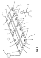
- a defense device 1 is intended to prevent or delay access of an intruder 2 inside a zone Z.
- This device comprises a support 3 which may have a a certain rigidity facilitating its maintenance on the ground.
- the support could for example be constituted by a metal or composite plate. It could be anchored to the ground for example by means of these stakes (not shown).
- the support will for example be rectangular and may have a length between 5 and 10m and a width of 1.5 to 2,5m.
- FIG 3 shows this device in section cross.
- the support 3 carries a bag 4 which is shown here schematically folded up.
- the bag has a inflatable envelope 10 which is arranged in a housing of protection 11.
- the envelope 10 of the bag is likely to be inflated by at least one gas generator 5 (three generators are shown in Figure 1). Such inflation will also cause the housing 11 to rupture.
- gas generator 5 is preferably a generator pyrotechnic similar to those used in the field of automotive safety.
- Pyrotechnic gas generators include a gas generating composition which is initiated by a ignition pyrotechnic component triggered by a electrical signal.
- the envelope 10 can be produced for example in a material that is both flexible and resistant for example in polyamide or Kevlar or an elastic material such as elastomer. It could possibly be reinforced, by example by stitching or glued rubber bands to the envelope and arranged in a network. Such a provision will make the envelope more resistant to pressure and tearing by external aggressions.
- the envelope will be made integral with the support for example by gluing or by means of clamps.
- Patent EP529371 which describes a material which can be used for to make the envelope for such a bag
- patents US5062367, FR2691706 and EP509655 which describe gas generators usable for automotive safety.
- the support 3 also carries several detectors intrusion 6, for example infrared detectors or millimeter, each with a detection field of 7 oriented towards the outside of zone Z.
- detectors intrusion 6 for example infrared detectors or millimeter, each with a detection field of 7 oriented towards the outside of zone Z.
- the detectors 6 will preferably be arranged regularly spaced along at least one of the largest support lengths 3.
- detectors 6 along the two lengths support 3.
- This arrangement allows make the device symmetrical and authorize the detection of intruder from one side or the other of support 3. On thus facilitates the operational implementation of the device by authorizing its installation according to two positions different along zone Z.
- the support 3 may also bear on its surface upper visible markings 8 ensuring signage the prohibition to enter the protected area.
- We may for example provide brightly colored bands, prohibitions, signage ....
- the device according to the invention also includes electronic control means 9 which are connected to detectors 6 as well as gas generators 5.
- These means will include algorithms allowing ensure a comparison between the signals provided by the or detectors 6 and those put in the device memories.
- the detectors 6 After installation of the device along one of the boundaries of the zone Z to be protected, we activate the detectors 6 arranged along one side of the support. These detectors monitor the area surrounding zone Z.
- the control means 9 When an intruder 2 approaches the device from a distance which will be adjustable from the control means according to the effect to be produced on the intruder (of the order of 2 to 5 m), the control means 9 cause the envelope 10 to inflate (see figure 2).
- This envelope is deployed above the support 3 of so as to cover a cylindrical volume of axis 12 substantially parallel to the support 3.
- the envelope 10 provides a barrier linear whose dimensions are such that the passage of the intruder through the device is prohibited or all at least embarrassed.
- control means 9 can be connected an alarm system producing an audible signal and / or bright and also transmitting an alert to a remote monitoring.
- the detectors 6 will preferably be fixed in a way removable on support 3 to facilitate maintenance and storage.
- the bag 10 can also be covered externally an adhesive material such as an epoxy or acrylate adhesive. A such an arrangement will further slow down the possible progression of an intruder.
- Figure 4 shows a device according to a second mode for carrying out the invention.
- the support 3 is made in the form of a flexible mat for example in rubber or foam 15 to 25 mm thick.
- This carpet carries the envelope 10 folded and made integral with the carpet, for example by overmolding or gluing.
- the end 19 of the mat 3 comprises connecting means mechanical 17, such as latches, which are intended to allow the attachment of a support 3 with a other similar support. In order to allow such joining, the other end of the mat will carry means additional links.
- the mat 3 carries at one end 19 of the means electrical connection 13 which are connected by conductors 15 to connectors 14, regularly distributed along the support 3 and which allow the connection of detectors 6.
- the other end of the mat carries means for additional connection.
- the electrical connection means 13 are also intended to electrically connect the support 3 to a support similar.
- the flexible support 3 is substantially rectangular. he can be wound along a winding axis 16 which is parallel to its width.
- the connectors 14 have a thickness reduced which does not interfere with the winding of the support 3.
- the envelope 10 of the bag will be inflatable here by means of gas generator external (pyrotechnic or a gas cylinder under pressure) which will be connected to it via a pipeline 18.
- gas generator external pyrotechnic or a gas cylinder under pressure
- Such an embodiment makes it possible to facilitate the storage and implementation of the device according to the invention.
- the supports are then fixed to each other by the connecting means 17 and electrically connected to each other to the others by the connection means 13.
- Figure 6 thus shows a device according to the invention which is formed by the joining of three supports 3a, 3b and 3c. These supports may be produced in the form of flexible mats such as that shown in Figure 4 or in the form of rigid or semi-rigid supports such as shown in Figure 1.
- a single control means 9 is connected to the different supports.
- the electrical connections 20 are made between the different supports 3 and a connection 21 connects all the supports to the control means 9.
- Connections 20 and 21 will preferably be made in the form of a "BUS" link (transmission cable data and energy). Detectors 6 and gas generators of different supports 3a, 3b and 3c will have an individual address which will be recognized by control means and the control means can thus determine precisely at which supports 3a, 3b or 3c there is an intrusion. Control means 9 will then cause the appropriate envelope to inflate.
- the detectors 6 of the latter will transmit a detection signal to the control means 9 which will cause the envelope of the latter to swell support.
- control means 9 with a receiving device 22 of remote control commands 23 which are sent by a remote control station 24.
- Figure 5 shows a third embodiment of the invention in which the support 3 is equipped with a tube launcher 25 whose axis 26 is vertical (and perpendicular to the support 3 placed on the ground).
- the tube 25 contains a projectile 27 which can be ejected from the tube 25 in the direction 26 by lighting a pyrotechnic ejection charge 28.
- the projectile 27 contains a charge which will be preferably a warning charge, i.e. which is triggered with delay on the trajectory of the projectile and which generates noise and / or light at a distance from the ground of the order 5 m.
- a warning charge i.e. which is triggered with delay on the trajectory of the projectile and which generates noise and / or light at a distance from the ground of the order 5 m.
- the projectile 27 of an incapacitating charge, for example of a composition tear gas which will be dispersed on the trajectory when firing the projectile.
- an incapacitating charge for example of a composition tear gas which will be dispersed on the trajectory when firing the projectile.
- Detectors 6 signal the approach of an intruder to a distance of the order of a few m (which is a function of the detector technology used).
- the detection signal is operated by the control means 9 which cause the shot of the warning projectile which has the effect of dissuading the intruder.
- alert information may be transmitted by the control means 9 to a remote control.
- the detectors 6 continue to transmit a presence signal to the means of command 9. These then trigger the inflation of envelope 10.
- Such an embodiment of the invention allows ensure a graduated response (warning then barrier) to intrusion attempts detected.
- the launch tube will preferably be mounted in a way removable on the support 3 to allow its replacement.
- the projectile may also be integral of a propellant charge to form a munition which could be replaced or renewed as needed operational.
- tubes may be provided launchers oriented in different directions and possibly attached to a positioning platform in site and / or deposit.
- sensors whose orientation will be such that it will allow a location of intruder position.
- the means of order can then choose or orient the tubes appropriate to the location of the threat detected.
- control means can then cause the most ammunition to fire appropriate according to the signals provided by the different detectors.
Landscapes
- Physics & Mathematics (AREA)
- General Physics & Mathematics (AREA)
- Engineering & Computer Science (AREA)
- General Engineering & Computer Science (AREA)
- Burglar Alarm Systems (AREA)
- Air Bags (AREA)
- Arc Welding In General (AREA)
- Control Of Motors That Do Not Use Commutators (AREA)
- Lighting Device Outwards From Vehicle And Optical Signal (AREA)
- Electronic Switches (AREA)
- Electrical Discharge Machining, Electrochemical Machining, And Combined Machining (AREA)
Claims (17)
- Vorrichtung (1) zum Verteidigen eines Bereiches (Z) gegen das Eindringen umfassend wenigstens einen Sack (4), der fest mit wenigstens einem Träger (3) verbunden ist, wobei der Sack eine dehnbare Hülle (10) umfasst, die geeignet ist, von wenigstens einem Gas- oder Fluidgenerator (5) aufgeblasen zu werden, der von Steuermitteln (9) ausgelöst wird, wobei sich die Hülle (10) derartig über dem Träger (3) entfaltet, dass ein im Wesentlichen zylindrisches Volumen mit ausreichenden Abmessungen abgedeckt wird, um es zu ermöglichen, eine Barriere zu bilden, die ein Vorankommen in Richtung des durch die Vorrichtung verteidigten Bereiches stören kann, der Träger sich in der Form einer Platte darstellt, die auf den Boden gelegt wird, und die Achse (12) des im Wesentlichen zylindrischen Volumens im Wesentlichen parallel zur Platte und somit zum Boden verläuft.
- Vorrichtung nach Anspruch 1, dadurch gekennzeichnet, dass der Träger (3) wenigstens einen Eindring-Detektor (6) trägt oder mit wenigstens einem Eindring-Detektor (6) ausgerüstet sein kann, der mit Steuermitteln (9) verbunden ist.
- Vorrichtung nach einem der Ansprüche 1 oder 2, dadurch gekennzeichnet, dass der Träger (3) wenigstens ein Werferrohr (25) trägt oder mit wenigstens einem Werferrohr (25) von wenigstens einem Projektil (27) ausgerüstet sein kein.
- Vorrichtung nach Anspruch 3, dadurch gekennzeichnet, dass sie wenigstens ein Werferrohr trägt oder mit wenigstens einem Werferrohr ausgerüstet sein kann, das entlang einer im Wesentlichen senkrechten Richtung (26) orientiert ist und ein Schreck-Projektil (27) aufnehmen kann.
- Vorrichtung nach Anspruch 4, dadurch gekennzeichnet, dass das Schreck-Projektil eine pyrotechnische Ladung umfasst, die Geräusch und/oder Licht erzeugt.
- Vorrichtung nach Anspruch 4, dadurch gekennzeichnet, dass das Schreck-Projektil eine Tränen reizende Ladung umfasst.
- Vorrichtung nach einem der Ansprüche 3 bis 6, dadurch gekennzeichnet, dass das Werferrohr (25) durch die Steuermittel (9) in Abhängigkeit von der Erfassung eines Eindringens in Betrieb gesetzt wird.
- Vorrichtung nach Anspruch 7, dadurch gekennzeichnet, dass das Aufblasen des Sacks (4) im Falle der Fortdauer der Erfassung eines Eindringens nach dem Auslösen des Werferrohres (25) durch die Steuermittel (9) ausgelöst wird.
- Vorrichtung nach einem der Ansprüche 1 bis 8, dadurch gekennzeichnet, dass der Träger (3) eine im Wesentlichen rechteckige Oberfläche besitzt und weist eine ausreichende Biegsamkeit auf, um dessen Aufwickeln um eine parallel zu seiner Breite verlaufenden Wickelachse (16) zu ermöglichen.
- Vorrichtung nach einem der Ansprüche 1 bis 9, dadurch gekennzeichnet, dass der Träger (3) wenigstens eine kennzeichnende Verbotsmarkierung (8) umfasst.
- Vorrichtung nach einem der Ansprüche 1 bis 10, dadurch gekennzeichnet, dass der Träger (3) an wenigstens einem seiner Enden (19) elektrische Anschlussmittel (13) trägt, die es erlauben, ihn mit wenigstens einem anderen analogen Träger zu verbinden.
- Vorrichtung nach einem der Ansprüche 1 bis 11, dadurch gekennzeichnet, dass der Träger (3) an wenigstens einem seiner Enden (19) mechanische Verbindungsmittel (17) trägt, die es erlauben, ihn mit wenigstens einem anderen analogen Träger fest zu verbinden.
- Vorrichtung nach einem der Ansprüche 1 bis 12, dadurch gekennzeichnet, dass die Steuermittel (9) für wenigstens zwei Träger (3) gemeinsam sind.
- Vorrichtung zum Verteidigen nach einem der Ansprüche 1 bis 13, dadurch gekennzeichnet, dass der Gasgenerator (5) wenigstens einen pyrotechnischen Generator umfasst.
- Vorrichtung zum Verteidigen nach einem der Ansprüche 1 bis 14, dadurch gekennzeichnet, dass der Gasgenerator (5) wenigstens eine Druckgasflasche umfasst.
- Vorrichtung zum Verteidigen nach einem der Ansprüche 1 bis 15, dadurch gekennzeichnet, dass die Steuermittel (9) mit Mitteln (22) zum Empfang von ferngesteuerten Befehlen verbunden sind.
- Vorrichtung nach einem der Ansprüche 1 bis 16, dadurch gekennzeichnet, dass der Sack (4) mit einem haftenden Material überzogen ist.
Applications Claiming Priority (2)
| Application Number | Priority Date | Filing Date | Title |
|---|---|---|---|
| FR9906451A FR2793929B1 (fr) | 1999-05-20 | 1999-05-20 | Dispositif de defense d'une zone contre l'intrusion |
| FR9906451 | 1999-05-20 |
Publications (2)
| Publication Number | Publication Date |
|---|---|
| EP1054370A1 EP1054370A1 (de) | 2000-11-22 |
| EP1054370B1 true EP1054370B1 (de) | 2004-08-04 |
Family
ID=9545842
Family Applications (1)
| Application Number | Title | Priority Date | Filing Date |
|---|---|---|---|
| EP00401179A Expired - Lifetime EP1054370B1 (de) | 1999-05-20 | 2000-04-28 | Vorrichtung zum Schutz eines Gebietes gegen Eindringen |
Country Status (6)
| Country | Link |
|---|---|
| US (1) | US6470784B1 (de) |
| EP (1) | EP1054370B1 (de) |
| AT (1) | ATE272878T1 (de) |
| DE (1) | DE60012623T2 (de) |
| ES (1) | ES2223416T3 (de) |
| FR (1) | FR2793929B1 (de) |
Families Citing this family (13)
| Publication number | Priority date | Publication date | Assignee | Title |
|---|---|---|---|---|
| US6666124B2 (en) * | 2002-05-23 | 2003-12-23 | Zodiac Hurricane Technologies, Inc. | Fast deployment, high pressure inflatable panels and watercraft or other objects with armor or other protection |
| US6688555B1 (en) * | 2002-07-30 | 2004-02-10 | Philip Kneisl | Anti-hijacking system |
| US20040200931A1 (en) * | 2003-02-25 | 2004-10-14 | Sanford William C. | Aircraft air bag unwanted intrusion preventative deployment system |
| US7963075B2 (en) * | 2005-11-22 | 2011-06-21 | Warwick Mills, Inc. | Inflatable barrier |
| DE102006013007B4 (de) * | 2006-03-22 | 2007-12-13 | Diehl Bgt Defence Gmbh & Co. Kg | Bewegungshemmnis |
| US8967049B2 (en) * | 2011-01-28 | 2015-03-03 | The United States Of America As Represented By The Secretary Of The Navy | Solid lined fabric and a method for making |
| US8677881B2 (en) * | 2012-04-10 | 2014-03-25 | The Boeing Company | Method and system for attenuating shock waves via an inflatable enclosure |
| US9360281B1 (en) | 2012-09-06 | 2016-06-07 | John De Gaglia | Rapidly deploying ballistic barrier curtain |
| US9134097B1 (en) * | 2012-09-06 | 2015-09-15 | John De Gaglia | Rapidly deploying ballistic barrier curtain |
| WO2014138577A1 (en) * | 2013-03-07 | 2014-09-12 | Battleware Technologies, Inc. | Inflatable frame for flexible ballistic shield with integrated alert and tracking systems |
| US9032878B1 (en) * | 2013-08-30 | 2015-05-19 | The United States Of America As Represented By The Secretary Of The Army | Obscurant generating, ground-based, networked munition |
| DE102014005068A1 (de) * | 2014-04-07 | 2015-06-11 | Bundesrepublik Deutschland, vertreten durch das Bundesministerium der Verteidigung, vertreten durch das Bundesamt für Ausrüstung, Informationstechnik und Nutzung der Bundeswehr | Modulare Sperrvorrichtung |
| US10192418B1 (en) | 2018-06-11 | 2019-01-29 | Geoffrey M. Kern | System and method for perimeter security |
Family Cites Families (8)
| Publication number | Priority date | Publication date | Assignee | Title |
|---|---|---|---|---|
| US1434132A (en) * | 1918-10-25 | 1922-10-31 | Charles H Mcdonald | Picket alarm |
| US3214857A (en) * | 1963-10-10 | 1965-11-02 | Felix A Tyrone | Burglar alarm unit |
| DE3804991C1 (de) * | 1988-02-18 | 1999-07-08 | Lfk Gmbh | Einrichtung zum Schutz von Aktiv-Panzerungen |
| US5649466A (en) * | 1992-11-25 | 1997-07-22 | The United States Of America As Represented By The Secretary Of The Army | Method of rapidly deploying volume-displacement devices for restraining movement of objects |
| FR2727506B1 (fr) * | 1994-11-30 | 1997-01-24 | Giat Ind Sa | Dispositif de protection d'un vehicule ou d'une structure |
| WO1997023852A1 (de) * | 1995-12-21 | 1997-07-03 | Horst Georg Bugiel | Einrichtung zum vorübergehenden ferstsetzen eines täters |
| DE19715464A1 (de) * | 1997-04-14 | 1998-10-29 | Martin Albrecht | Aktionsverhinderungssystem |
| US6029558A (en) * | 1997-05-12 | 2000-02-29 | Southwest Research Institute | Reactive personnel protection system |
-
1999
- 1999-05-20 FR FR9906451A patent/FR2793929B1/fr not_active Expired - Fee Related
-
2000
- 2000-04-27 US US09/559,097 patent/US6470784B1/en not_active Expired - Fee Related
- 2000-04-28 EP EP00401179A patent/EP1054370B1/de not_active Expired - Lifetime
- 2000-04-28 DE DE60012623T patent/DE60012623T2/de not_active Expired - Fee Related
- 2000-04-28 ES ES00401179T patent/ES2223416T3/es not_active Expired - Lifetime
- 2000-04-28 AT AT00401179T patent/ATE272878T1/de not_active IP Right Cessation
Also Published As
| Publication number | Publication date |
|---|---|
| US6470784B1 (en) | 2002-10-29 |
| FR2793929A1 (fr) | 2000-11-24 |
| DE60012623T2 (de) | 2005-01-05 |
| EP1054370A1 (de) | 2000-11-22 |
| FR2793929B1 (fr) | 2001-07-06 |
| ES2223416T3 (es) | 2005-03-01 |
| DE60012623D1 (de) | 2004-09-09 |
| ATE272878T1 (de) | 2004-08-15 |
Similar Documents
| Publication | Publication Date | Title |
|---|---|---|
| EP1054370B1 (de) | Vorrichtung zum Schutz eines Gebietes gegen Eindringen | |
| US7882775B2 (en) | Non-lethal restraint device with diverse deployability applications | |
| US8561516B2 (en) | System and method for non-lethal vehicle restraint | |
| US8613241B2 (en) | Aquatic restraint device | |
| FR2727506A1 (fr) | Dispositif de protection d'un vehicule ou d'une structure | |
| FR2739921A1 (fr) | Dispositif de protection pour vehicule blinde | |
| EP0273787B1 (de) | Geschoss zum indirekten Angriff auf Panzerfahrzeuge | |
| JP2002525557A (ja) | 赤外線放射閃光装置を放出するための電子的に構成可能な曳航デコイ | |
| US4286498A (en) | Decoy rounds and their method of fabrication | |
| JP2003518236A (ja) | エリア妨害 | |
| US6892983B2 (en) | Anti-hijacking system | |
| EP2995558B1 (de) | Luftfahrzeug, das mindestens einen notsignalsender umfasst | |
| FR2518734A1 (fr) | Systeme de defense de zone a effet de saturation | |
| FR2789484A1 (fr) | Dispositif de defense a letalite reduite | |
| US4864277A (en) | Radio alarm system | |
| FR2761768A1 (fr) | Procede de destruction de mines terrestres posees et dissimulees et dispositif pour la mise en oeuvre de ce procede | |
| EP0388264A1 (de) | Zielmarkierungsvorrichtung zum Anziehen von zielsuchenden Geschossen | |
| BE1006541A3 (fr) | Leurre multispectral. | |
| FR2683305A1 (fr) | Perfectionnement aux systemes comprenant un element allonge deployable a fonction pyrotechnique. | |
| US8550005B1 (en) | Non-lethal delivery canister, threat mitigation system, and methods for mitigating bomber and perpetrator threats | |
| CN1955630A (zh) | 捕捉装置 | |
| FR2907206A1 (fr) | Blindage actif avec capteurs infrarouges | |
| FR2863055A1 (fr) | Procede de detection de l'approche d'une cible, dispositif de detection et dispositif de protection mettant en oeuvre ce procede | |
| FR2518733A1 (fr) | Systeme de defense de zone a plate-forme d'observation | |
| WO1999049135A1 (fr) | Dispositif pour le deploiement sur le sol d'un revetement de surface provisoire stocke enroule |
Legal Events
| Date | Code | Title | Description |
|---|---|---|---|
| PUAI | Public reference made under article 153(3) epc to a published international application that has entered the european phase |
Free format text: ORIGINAL CODE: 0009012 |
|
| AK | Designated contracting states |
Kind code of ref document: A1 Designated state(s): AT BE CH CY DE DK ES FI FR GB GR IE IT LI LU MC NL PT SE |
|
| AX | Request for extension of the european patent |
Free format text: AL;LT;LV;MK;RO;SI |
|
| 17P | Request for examination filed |
Effective date: 20010118 |
|
| AKX | Designation fees paid |
Free format text: AT BE CH CY DE DK ES FI FR GB GR IE IT LI LU MC NL PT SE |
|
| AXX | Extension fees paid |
Free format text: AL PAYMENT 20010118;LT PAYMENT 20010118;LV PAYMENT 20010118;MK PAYMENT 20010118;RO PAYMENT 20010118;SI PAYMENT 20010118 |
|
| 17Q | First examination report despatched |
Effective date: 20030707 |
|
| GRAP | Despatch of communication of intention to grant a patent |
Free format text: ORIGINAL CODE: EPIDOSNIGR1 |
|
| GRAS | Grant fee paid |
Free format text: ORIGINAL CODE: EPIDOSNIGR3 |
|
| GRAA | (expected) grant |
Free format text: ORIGINAL CODE: 0009210 |
|
| AK | Designated contracting states |
Kind code of ref document: B1 Designated state(s): AT BE CH CY DE DK ES FI FR GB GR IE IT LI LU MC NL PT SE |
|
| AX | Request for extension of the european patent |
Extension state: AL LT LV MK RO SI |
|
| PG25 | Lapsed in a contracting state [announced via postgrant information from national office to epo] |
Ref country code: NL Free format text: LAPSE BECAUSE OF FAILURE TO SUBMIT A TRANSLATION OF THE DESCRIPTION OR TO PAY THE FEE WITHIN THE PRESCRIBED TIME-LIMIT Effective date: 20040804 Ref country code: IE Free format text: LAPSE BECAUSE OF FAILURE TO SUBMIT A TRANSLATION OF THE DESCRIPTION OR TO PAY THE FEE WITHIN THE PRESCRIBED TIME-LIMIT Effective date: 20040804 Ref country code: AT Free format text: LAPSE BECAUSE OF FAILURE TO SUBMIT A TRANSLATION OF THE DESCRIPTION OR TO PAY THE FEE WITHIN THE PRESCRIBED TIME-LIMIT Effective date: 20040804 |
|
| REG | Reference to a national code |
Ref country code: GB Ref legal event code: FG4D Free format text: NOT ENGLISH |
|
| REG | Reference to a national code |
Ref country code: CH Ref legal event code: EP Ref country code: CH Ref legal event code: NV Representative=s name: ING. MARCO ZARDI C/O M. ZARDI & CO. S.A. |
|
| GBT | Gb: translation of ep patent filed (gb section 77(6)(a)/1977) |
Effective date: 20040805 |
|
| REG | Reference to a national code |
Ref country code: IE Ref legal event code: FG4D Free format text: FRENCH |
|
| REF | Corresponds to: |
Ref document number: 60012623 Country of ref document: DE Date of ref document: 20040909 Kind code of ref document: P |
|
| REG | Reference to a national code |
Ref country code: SE Ref legal event code: TRGR |
|
| PG25 | Lapsed in a contracting state [announced via postgrant information from national office to epo] |
Ref country code: DK Free format text: LAPSE BECAUSE OF FAILURE TO SUBMIT A TRANSLATION OF THE DESCRIPTION OR TO PAY THE FEE WITHIN THE PRESCRIBED TIME-LIMIT Effective date: 20041104 |
|
| REG | Reference to a national code |
Ref country code: GR Ref legal event code: EP Ref document number: 20040403781 Country of ref document: GR |
|
| NLV1 | Nl: lapsed or annulled due to failure to fulfill the requirements of art. 29p and 29m of the patents act | ||
| LTIE | Lt: invalidation of european patent or patent extension |
Effective date: 20040804 |
|
| REG | Reference to a national code |
Ref country code: ES Ref legal event code: FG2A Ref document number: 2223416 Country of ref document: ES Kind code of ref document: T3 |
|
| REG | Reference to a national code |
Ref country code: IE Ref legal event code: FD4D |
|
| PG25 | Lapsed in a contracting state [announced via postgrant information from national office to epo] |
Ref country code: LU Free format text: LAPSE BECAUSE OF NON-PAYMENT OF DUE FEES Effective date: 20050428 Ref country code: CY Free format text: LAPSE BECAUSE OF FAILURE TO SUBMIT A TRANSLATION OF THE DESCRIPTION OR TO PAY THE FEE WITHIN THE PRESCRIBED TIME-LIMIT Effective date: 20050428 |
|
| PG25 | Lapsed in a contracting state [announced via postgrant information from national office to epo] |
Ref country code: MC Free format text: LAPSE BECAUSE OF NON-PAYMENT OF DUE FEES Effective date: 20050430 Ref country code: BE Free format text: LAPSE BECAUSE OF NON-PAYMENT OF DUE FEES Effective date: 20050430 |
|
| PLBE | No opposition filed within time limit |
Free format text: ORIGINAL CODE: 0009261 |
|
| STAA | Information on the status of an ep patent application or granted ep patent |
Free format text: STATUS: NO OPPOSITION FILED WITHIN TIME LIMIT |
|
| 26N | No opposition filed |
Effective date: 20050506 |
|
| BERE | Be: lapsed |
Owner name: *GIAT INDUSTRIES Effective date: 20050430 |
|
| PGFP | Annual fee paid to national office [announced via postgrant information from national office to epo] |
Ref country code: FI Payment date: 20060323 Year of fee payment: 7 |
|
| PGFP | Annual fee paid to national office [announced via postgrant information from national office to epo] |
Ref country code: GR Payment date: 20060327 Year of fee payment: 7 |
|
| PGFP | Annual fee paid to national office [announced via postgrant information from national office to epo] |
Ref country code: CH Payment date: 20060329 Year of fee payment: 7 |
|
| PGFP | Annual fee paid to national office [announced via postgrant information from national office to epo] |
Ref country code: ES Payment date: 20060406 Year of fee payment: 7 |
|
| PGFP | Annual fee paid to national office [announced via postgrant information from national office to epo] |
Ref country code: DE Payment date: 20070327 Year of fee payment: 8 Ref country code: SE Payment date: 20070327 Year of fee payment: 8 |
|
| PGFP | Annual fee paid to national office [announced via postgrant information from national office to epo] |
Ref country code: GB Payment date: 20070328 Year of fee payment: 8 |
|
| REG | Reference to a national code |
Ref country code: CH Ref legal event code: PL |
|
| BERE | Be: lapsed |
Owner name: *GIAT INDUSTRIES Effective date: 20050430 |
|
| PG25 | Lapsed in a contracting state [announced via postgrant information from national office to epo] |
Ref country code: PT Free format text: LAPSE BECAUSE OF NON-PAYMENT OF DUE FEES Effective date: 20050104 |
|
| PGFP | Annual fee paid to national office [announced via postgrant information from national office to epo] |
Ref country code: IT Payment date: 20070619 Year of fee payment: 8 |
|
| PG25 | Lapsed in a contracting state [announced via postgrant information from national office to epo] |
Ref country code: FI Free format text: LAPSE BECAUSE OF NON-PAYMENT OF DUE FEES Effective date: 20070428 |
|
| PG25 | Lapsed in a contracting state [announced via postgrant information from national office to epo] |
Ref country code: LI Free format text: LAPSE BECAUSE OF NON-PAYMENT OF DUE FEES Effective date: 20070430 Ref country code: CH Free format text: LAPSE BECAUSE OF NON-PAYMENT OF DUE FEES Effective date: 20070430 |
|
| REG | Reference to a national code |
Ref country code: ES Ref legal event code: FD2A Effective date: 20070430 |
|
| PG25 | Lapsed in a contracting state [announced via postgrant information from national office to epo] |
Ref country code: ES Free format text: LAPSE BECAUSE OF NON-PAYMENT OF DUE FEES Effective date: 20070430 Ref country code: GR Free format text: LAPSE BECAUSE OF NON-PAYMENT OF DUE FEES Effective date: 20071102 |
|
| EUG | Se: european patent has lapsed | ||
| GBPC | Gb: european patent ceased through non-payment of renewal fee |
Effective date: 20080428 |
|
| PG25 | Lapsed in a contracting state [announced via postgrant information from national office to epo] |
Ref country code: DE Free format text: LAPSE BECAUSE OF NON-PAYMENT OF DUE FEES Effective date: 20081101 |
|
| PG25 | Lapsed in a contracting state [announced via postgrant information from national office to epo] |
Ref country code: GB Free format text: LAPSE BECAUSE OF NON-PAYMENT OF DUE FEES Effective date: 20080428 |
|
| PG25 | Lapsed in a contracting state [announced via postgrant information from national office to epo] |
Ref country code: IT Free format text: LAPSE BECAUSE OF NON-PAYMENT OF DUE FEES Effective date: 20080428 |
|
| PG25 | Lapsed in a contracting state [announced via postgrant information from national office to epo] |
Ref country code: SE Free format text: LAPSE BECAUSE OF NON-PAYMENT OF DUE FEES Effective date: 20080429 |
|
| PGFP | Annual fee paid to national office [announced via postgrant information from national office to epo] |
Ref country code: FR Payment date: 20120426 Year of fee payment: 13 |
|
| REG | Reference to a national code |
Ref country code: FR Ref legal event code: ST Effective date: 20131231 |
|
| PG25 | Lapsed in a contracting state [announced via postgrant information from national office to epo] |
Ref country code: FR Free format text: LAPSE BECAUSE OF NON-PAYMENT OF DUE FEES Effective date: 20130430 |