EP1054548B1 - Telekommunikationsendgerät - Google Patents
Telekommunikationsendgerät Download PDFInfo
- Publication number
- EP1054548B1 EP1054548B1 EP00110406A EP00110406A EP1054548B1 EP 1054548 B1 EP1054548 B1 EP 1054548B1 EP 00110406 A EP00110406 A EP 00110406A EP 00110406 A EP00110406 A EP 00110406A EP 1054548 B1 EP1054548 B1 EP 1054548B1
- Authority
- EP
- European Patent Office
- Prior art keywords
- recess
- cover
- telecommunications terminal
- locking plate
- terminal according
- Prior art date
- Legal status (The legal status is an assumption and is not a legal conclusion. Google has not performed a legal analysis and makes no representation as to the accuracy of the status listed.)
- Expired - Lifetime
Links
- 230000000007 visual effect Effects 0.000 claims abstract 6
- 230000013011 mating Effects 0.000 claims description 13
- 239000010454 slate Substances 0.000 claims 1
- 230000003287 optical effect Effects 0.000 description 20
- 238000006073 displacement reaction Methods 0.000 description 6
- 238000003780 insertion Methods 0.000 description 4
- 230000037431 insertion Effects 0.000 description 4
- 239000000853 adhesive Substances 0.000 description 1
- 230000001070 adhesive effect Effects 0.000 description 1
- 239000004973 liquid crystal related substance Substances 0.000 description 1
- 239000000463 material Substances 0.000 description 1
- 239000012780 transparent material Substances 0.000 description 1
Images

Classifications
-
- H—ELECTRICITY
- H04—ELECTRIC COMMUNICATION TECHNIQUE
- H04M—TELEPHONIC COMMUNICATION
- H04M1/00—Substation equipment, e.g. for use by subscribers
- H04M1/02—Constructional features of telephone sets
- H04M1/0295—Mechanical mounting details of display modules
Definitions
- the invention relates to a telecommunications terminal with a housing having a recess for receiving an optical display means.
- a cover and receiving device for optical display means is known, which is mounted in a housing cap ofInstitutmunjkationsendellan, in which the cover has a raised window and cylindrical receptacles with patch cuboid Liclitaustrittnö réelleen and made of transparent material of the same material as that of Case cap order.
- receiving support plate pins and posts are provided and for the passage of a web of the housing cap is a slot between the window and recordings.
- US Pat. No. 5,077,832 describes a radio with optional display. Instead of a display, a simple cover can be screwed from the inside into a radio housing.
- US Pat. No. 4,578,739 discloses a telecommunication terminal comprising a housing with a recess into which a display element can be inserted.
- the display element is protected by a cover that fits positively into the recess.
- the housing must be opened on another side of the housing.
- Object of the present invention is to provide a telecommunication terminal, which ensures a simple and secure attachment and protected arrangement of an optical display means in the housing of the telecommunication terminal.
- the solution according to the invention allows a simple and secure attachment and protected arrangement of an optical display means in the housing of a Wegmunikationsgendtechniks.
- the locking plate is positively and / or non-positively connectable by means of locking elements with the recess mounted on the counter-locking elements, wherein the locking elements and counter-locking elements are formed and arranged so that the locking plate with a substantially parallel to the first sliding movement of the cover sliding movement with the housing of the telecommunication terminal is connectable.
- the locking plate is connected to a substantially parallel to the first sliding movement of the cover plate sliding movement with the housing or the recess in the housing cap of the telecommunication terminal, the cover is effectively locked and so as to minimize the safety of unintentionally removing the cover from the optical display means.
- the locking plate combines the locking function with an interchangeable arrangement of a support for characters and / or symbols such as manufacturer's instructions, type designations and the like.
- the locking plate may be at least partially transparent and cover an optical display means for displaying alphanumeric characters and / or symbols, or integrate an optical display means for displaying alphanumeric characters and / or symbols.
- An advantageous embodiment of the solution according to the invention is characterized in that at least part of the interlocking elements and / or counter-interlocking elements and at least a part of the locking elements of the recess and the counter-locking elements of the locking plate is designed in the manner of a bayonet closure.
- the recess and the cover can be formed rectangular and the interlocking elements and counter-interlocking elements are arranged on two mutually perpendicular sides of the recess and the cover.
- at least one further form-locking element can be arranged on a third side of the recess and the associated third side of the cover.
- the sum of the length of the side edge of the cover and the side edge of the lock plate is equal to or approximately equal to the length of the side edge of the recess and in the assembled state of the cover and the locking plate abut the longitudinal sides of the locking plate at the upper or lower edge of the recess and the upper or lower edge of the cover.
- the rectangular locking plate can be slid over the surface of the cover adjacent the top or bottom edge of the cover.
- Figure 1 shows a perspective view of a housing cap 1 and a top of a telecommunication terminal, an insertable into the housing cap 1 optical display means 3 in the form of an LCD display and an at least partially transparent cover 4 for the optical display means 3 and as, log window formed locking plate 5.
- the assignment of the individual parts and their connection to the recess 2 of the housing cap 1 is indicated by dotted lines and arrows and will be explained in detail below.
- the housing cap 1 has a housing shell 10 and a handset rest 11, which is connectable to a corresponding, unspecified lower shell to form the housing for the telecommunication terminal.
- the housing shell 10 has in addition to a plurality of openings for operating and display elements on a recess 2, in which the optical display means 3 is used in the form of an LCD display and connected, for example by means of an adhesive connection with the housing cap 1.
- a wiring harness 30 which is guided through a corresponding opening in the housing cap 1 and connected to an electronic circuit of the telecommunication terminal.
- the recess 2 is designed rectangular in this embodiment and has an adjacent to the surface of the housing cap 1 upper edge 22 and opposite a lower edge 23 and the upper and lower edge connecting side edges 20 and 21, of which the side edge 20 stepped relative to the side surface of the housing shell 10 is.
- a gradation 29 for receiving and centering of the optical display means 3 via a protruding from the underside web 31 is provided.
- a plurality of openings 24, 251, 252, 261, 262, 27, 28 are provided which serve as interlocking elements for receiving counter-positive locking elements of the cover 4 and as locking elements for receiving counter-locking elements of the locking plate 5 ,
- undercut opening 24 is provided, in which the rectangular hook 44 of the cover 4 is inserted.
- Two provided on the lower edge 23 of the recess 2 slots 251, 252 serve to receive webs 45, 46 which project from the lower edge 43 of the cover 4 at right angles.
- the cover 4 has a perpendicular from the surface of the cover 4 angled side edge 40, which has a substantially parallel to the surface of the cover 4 extending in the region of the upper edge 42 of the cover 4 hook-shaped bent portion 47.
- the cover 4 is inserted from the outer (right) side edge of the housing shell 10 in the recess 2 and laterally displaced in the direction of arrow A until the side edge 40 of the cover 4 on the stepped side edge 20 of the recess 2 rests and the rectangular hook 44 of the cover 4 is inserted into the undercut opening 24 of the recess 2.
- the hook-shaped bent portion 47 of the cover 4 engages in the groove 27 of the recess 2 a.
- the cover 4 is connected to the side edges 20, 21 and at the lower edge 23 with the recess 2 and due to the arrangement of the rectangular hook 44 behind the undercut of the undercut opening 24, a removal of the cover 4 from the housing shell 10 by lateral displacement opposite the direction of the arrow A not possible. Only a combined displacement of the cover 4 initially against the direction of arrow B and then against the direction of the arrow A dissolves the cover 4 from the recess 2 of the housing shell 10 and releases the optical display means 3.
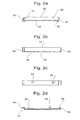
- FIGS. 2a to 2d show the locking plate 5 in detail, FIG. 2a showing a perspective view, FIG. 2b a front view, FIG. 2c a rear side view and FIG. 2d a side view of the locking plate 5.
- the locking plate 5 is formed as a rectangular plate having a surface 56 for receiving characters and / or symbols and hook-shaped locking elements 54, 55 on the narrow sides 50, 51 which are interconnected via the longitudinal sides 52, 53.
- On the back of the locking plate 5 are spaced from each other two hooks 57, 58 are arranged. which can be latched by lateral displacement of the locking plate 5 with openings 261, 262 at the upper edge 22 of the recess 2.
- the locking plate 5 with its hook-shaped locking element 54 in the undercut opening 28 at the top, to the upper edge 22 of the recess 2 of the side edge 21 adjacent undercut opening 28 is inserted and then pressed the adjacent to the narrow side 50 end of the surface 56 of the locking plate 5 down and by moving the locking plate 5 in the direction of arrow C are the arranged on the narrow side 50, designed as a locking element hook 55 in the groove 27 on the side edge 20 of the recess 2 and the hooks 57, 58 inserted into the apertures 261, 262 and locked with these.
- the locking plate 5 fills the space between the upper edge 42 of the cover 4 and the upper edge 22 of the recess 2, the cover 4 can not be moved against the direction of the arrow B and is thus within the recess 2 with the housing shell 10 and the housing cap 1 locked.
- the openings provided in the recess and parts of the optical display means 3 can be covered, so that the overall result is a closed surface and a pleasing appearance of the housing cap 1 with the therein arranged optical display means.
- the invention described above is not limited to the illustrated embodiment, in particular with regard to the design and function of the locking plate.
- the locking plate itself may be formed at least partially transparent and cover an LCD or LED display, with a logo or other alphanumeric character or symbol display is displayed so that the change of the logo only a corresponding control of the LCD / LBD Displays is required.
- the LCD / LED display may be formed as an optionally separated area of the optical display means.
- Another application and design of the locking plate may consist in that an LCD / LED display is integrated in the locking plate and, for example, one of the locking elements for contacting with a corresponding mating contact in the recess serves to the drive signals from an electronics of the telecommunication terminal to the LCD / To transmit LED display.
- the locking plate 5 is placed on the upper edge 22 of the recess 2 on the cover 4 and laterally in the direction of arrow C along the upper edge 22 of the recess 2 are moved to the arranged on the narrow sides 51, 52 of the locking plate 5 locking elements 54, 55 with the corresponding Counter-locking elements 27, 28 of the recess 2 are connected.
- the locking elements 54, 55 of the locking plate 5 are hook-shaped, i. consist of several times at right angles from the surface 56 of the locking plate 5 angled webs, wherein the arranged on the narrow side 50 of the locking plate 5 locking element 55 engages in the slot 27 on the side edge 20 of the recess 2, while the locking element 54 on the narrow side 51 of the locking plate. 5 engages in the undercut opening 28 in the region of the handle between the upper edge 22 and the side edge 21 of the recess 2.
- the longitudinal side 52 of the locking plate 5 is located at the upper edge 22 of the recess 2 or surmounted the upper edge 22.
- the other longitudinal side 53 of the locking plate 5 limits the surface 56 of the locking plate 5 and thus the Carrier field for alphanumeric drawing symbols.
Landscapes
- Engineering & Computer Science (AREA)
- Signal Processing (AREA)
- Telephone Set Structure (AREA)
- Input Circuits Of Receivers And Coupling Of Receivers And Audio Equipment (AREA)
- Casings For Electric Apparatus (AREA)
- Devices For Indicating Variable Information By Combining Individual Elements (AREA)
Applications Claiming Priority (2)
| Application Number | Priority Date | Filing Date | Title |
|---|---|---|---|
| DE29909075U | 1999-05-19 | ||
| DE29909075U DE29909075U1 (de) | 1999-05-19 | 1999-05-19 | Telekommunikationsendgerät |
Publications (3)
| Publication Number | Publication Date |
|---|---|
| EP1054548A2 EP1054548A2 (de) | 2000-11-22 |
| EP1054548A3 EP1054548A3 (de) | 2005-07-06 |
| EP1054548B1 true EP1054548B1 (de) | 2006-10-25 |
Family
ID=8073888
Family Applications (1)
| Application Number | Title | Priority Date | Filing Date |
|---|---|---|---|
| EP00110406A Expired - Lifetime EP1054548B1 (de) | 1999-05-19 | 2000-05-16 | Telekommunikationsendgerät |
Country Status (6)
| Country | Link |
|---|---|
| EP (1) | EP1054548B1 (da) |
| AT (1) | ATE343893T1 (da) |
| DE (2) | DE29909075U1 (da) |
| DK (1) | DK1054548T3 (da) |
| ES (1) | ES2274750T3 (da) |
| NO (1) | NO20002537L (da) |
Families Citing this family (3)
| Publication number | Priority date | Publication date | Assignee | Title |
|---|---|---|---|---|
| DE10053209A1 (de) * | 2000-10-26 | 2002-08-01 | Siemens Ag | Displayadapter für Komforttelefone |
| KR102218182B1 (ko) * | 2014-08-08 | 2021-02-22 | 엘지전자 주식회사 | 이동 단말기 |
| FR3021134B1 (fr) | 2014-05-14 | 2023-01-06 | Lg Electronics Inc | Terminal mobile |
Family Cites Families (2)
| Publication number | Priority date | Publication date | Assignee | Title |
|---|---|---|---|---|
| US4578739A (en) * | 1981-10-13 | 1986-03-25 | Motorola, Inc. | Quick disconnect and function change radio assembly |
| US5077832A (en) * | 1989-08-07 | 1991-12-31 | Ericsson Ge Mobile Communications Inc. | Radio transceiver with optional display |
-
1999
- 1999-05-19 DE DE29909075U patent/DE29909075U1/de not_active Expired - Lifetime
-
2000
- 2000-05-16 DK DK00110406T patent/DK1054548T3/da active
- 2000-05-16 ES ES00110406T patent/ES2274750T3/es not_active Expired - Lifetime
- 2000-05-16 DE DE50013650T patent/DE50013650D1/de not_active Expired - Lifetime
- 2000-05-16 NO NO20002537A patent/NO20002537L/no not_active Application Discontinuation
- 2000-05-16 AT AT00110406T patent/ATE343893T1/de not_active IP Right Cessation
- 2000-05-16 EP EP00110406A patent/EP1054548B1/de not_active Expired - Lifetime
Also Published As
| Publication number | Publication date |
|---|---|
| DE50013650D1 (de) | 2006-12-07 |
| NO20002537D0 (no) | 2000-05-16 |
| NO20002537L (no) | 2000-11-20 |
| ES2274750T3 (es) | 2007-06-01 |
| EP1054548A3 (de) | 2005-07-06 |
| ATE343893T1 (de) | 2006-11-15 |
| DE29909075U1 (de) | 1999-07-22 |
| EP1054548A2 (de) | 2000-11-22 |
| DK1054548T3 (da) | 2007-02-19 |
Similar Documents
| Publication | Publication Date | Title |
|---|---|---|
| DE3601847C2 (da) | ||
| EP1659411B1 (de) | Elektronischer Elektrizitätszähler | |
| EP1054548B1 (de) | Telekommunikationsendgerät | |
| DE3621262C2 (de) | Haltevorrichtung für ein elektronisches Display | |
| DE3150438C2 (de) | Gehäuse zur Aufnahme der zur Beschaltung einer Magnetspule eines Hydraulikventils oder dgl. erforderlichen elektrischen Bauteile | |
| DE4236353A1 (de) | Elektrische Baugruppe | |
| EP0158795B1 (de) | Bedienungsfeld für elektrische und elektronische Geräte | |
| EP0215398A2 (de) | Verschwenkbare Beschriftungsblende | |
| DE19839118C2 (de) | Konstruktionsanordnung für die Befestigung eines Bauelements auf einer gedruckten Leiterplatte und elektronische Geräte mit dieser Konstruktion | |
| DE2902052A1 (de) | Elektrisches geraet, insbesondere fernsprechgeraet, mit einem einen hohlraum umschliessenden gehaeuse | |
| DE4132267A1 (de) | Fixiervorrichtung fuer kennzeichenschilder innerhalb eines kennzeichenverstaerkers | |
| EP0446575A2 (de) | Montageplatte, insbesondere für Gehäuse der Fernmelde- und Datentechnik | |
| CH686173A5 (de) | Modulares Taschenmesser. | |
| EP0262084A2 (de) | Elektrotechnisches Bauelement | |
| DE3326906C2 (de) | Weidezaungerät | |
| EP1266371B1 (de) | Vorrichtung zur halterung von wendetafeln oder dergleichen | |
| DE3410983A1 (de) | Montageelement zur befestigung einer lcd-anzeige auf einer leiterplatte | |
| EP0849719B1 (de) | Vorrichtung zur Aufnahme zumindest eines Preis und/oder Produktinformationsträgers | |
| WO1992004688A1 (de) | Kontaktiereinrichtung für eine sim-karte | |
| DE10159739A1 (de) | Reitersicherungssockel für Sammelschienen | |
| EP1060444B1 (de) | Chassis zur aufnahme von elektronikkarten | |
| DE3881244T2 (de) | Scheidungsaufbau zum Aufteilen von Komponenten. | |
| DE60006050T2 (de) | Mobiltelefon mit einer beweglicher Fensterscheibe | |
| DE3544533A1 (de) | Relais mit montage-erleichternder halterung auf einer platine | |
| DE2139442B2 (de) | Kasettenschild |
Legal Events
| Date | Code | Title | Description |
|---|---|---|---|
| PUAI | Public reference made under article 153(3) epc to a published international application that has entered the european phase |
Free format text: ORIGINAL CODE: 0009012 |
|
| AK | Designated contracting states |
Kind code of ref document: A2 Designated state(s): AT BE CH CY DE DK ES FI FR GB GR IE IT LI LU MC NL PT SE |
|
| AX | Request for extension of the european patent |
Free format text: AL;LT;LV;MK;RO;SI |
|
| PUAL | Search report despatched |
Free format text: ORIGINAL CODE: 0009013 |
|
| AK | Designated contracting states |
Kind code of ref document: A3 Designated state(s): AT BE CH CY DE DK ES FI FR GB GR IE IT LI LU MC NL PT SE |
|
| AX | Request for extension of the european patent |
Extension state: AL LT LV MK RO SI |
|
| RAP1 | Party data changed (applicant data changed or rights of an application transferred) |
Owner name: DETEWE SYSTEMS GMBH |
|
| 17P | Request for examination filed |
Effective date: 20050720 |
|
| AKX | Designation fees paid |
Designated state(s): AT BE CH CY DE DK ES FI FR GB GR IE IT LI LU MC NL PT SE |
|
| GRAP | Despatch of communication of intention to grant a patent |
Free format text: ORIGINAL CODE: EPIDOSNIGR1 |
|
| GRAS | Grant fee paid |
Free format text: ORIGINAL CODE: EPIDOSNIGR3 |
|
| GRAA | (expected) grant |
Free format text: ORIGINAL CODE: 0009210 |
|
| AK | Designated contracting states |
Kind code of ref document: B1 Designated state(s): AT BE CH CY DE DK ES FI FR GB GR IE IT LI LU MC NL PT SE |
|
| PG25 | Lapsed in a contracting state [announced via postgrant information from national office to epo] |
Ref country code: FI Free format text: LAPSE BECAUSE OF FAILURE TO SUBMIT A TRANSLATION OF THE DESCRIPTION OR TO PAY THE FEE WITHIN THE PRESCRIBED TIME-LIMIT Effective date: 20061025 Ref country code: NL Free format text: LAPSE BECAUSE OF FAILURE TO SUBMIT A TRANSLATION OF THE DESCRIPTION OR TO PAY THE FEE WITHIN THE PRESCRIBED TIME-LIMIT Effective date: 20061025 |
|
| REG | Reference to a national code |
Ref country code: GB Ref legal event code: FG4D Free format text: NOT ENGLISH |
|
| REG | Reference to a national code |
Ref country code: CH Ref legal event code: EP |
|
| REG | Reference to a national code |
Ref country code: IE Ref legal event code: FG4D Free format text: LANGUAGE OF EP DOCUMENT: GERMAN |
|
| REF | Corresponds to: |
Ref document number: 50013650 Country of ref document: DE Date of ref document: 20061207 Kind code of ref document: P |
|
| REG | Reference to a national code |
Ref country code: SE Ref legal event code: TRGR |
|
| GBT | Gb: translation of ep patent filed (gb section 77(6)(a)/1977) |
Effective date: 20061220 |
|
| PGFP | Annual fee paid to national office [announced via postgrant information from national office to epo] |
Ref country code: IE Payment date: 20070319 Year of fee payment: 8 |
|
| PG25 | Lapsed in a contracting state [announced via postgrant information from national office to epo] |
Ref country code: PT Free format text: LAPSE BECAUSE OF FAILURE TO SUBMIT A TRANSLATION OF THE DESCRIPTION OR TO PAY THE FEE WITHIN THE PRESCRIBED TIME-LIMIT Effective date: 20070326 |
|
| NLV1 | Nl: lapsed or annulled due to failure to fulfill the requirements of art. 29p and 29m of the patents act | ||
| RAP2 | Party data changed (patent owner data changed or rights of a patent transferred) |
Owner name: AASTRA DETEWE GMBH |
|
| PGFP | Annual fee paid to national office [announced via postgrant information from national office to epo] |
Ref country code: AT Payment date: 20070425 Year of fee payment: 8 |
|
| ET | Fr: translation filed | ||
| PGFP | Annual fee paid to national office [announced via postgrant information from national office to epo] |
Ref country code: DK Payment date: 20070430 Year of fee payment: 8 |
|
| REG | Reference to a national code |
Ref country code: ES Ref legal event code: FG2A Ref document number: 2274750 Country of ref document: ES Kind code of ref document: T3 |
|
| PLBE | No opposition filed within time limit |
Free format text: ORIGINAL CODE: 0009261 |
|
| STAA | Information on the status of an ep patent application or granted ep patent |
Free format text: STATUS: NO OPPOSITION FILED WITHIN TIME LIMIT |
|
| 26N | No opposition filed |
Effective date: 20070726 |
|
| PGFP | Annual fee paid to national office [announced via postgrant information from national office to epo] |
Ref country code: BE Payment date: 20070426 Year of fee payment: 8 |
|
| PG25 | Lapsed in a contracting state [announced via postgrant information from national office to epo] |
Ref country code: MC Free format text: LAPSE BECAUSE OF NON-PAYMENT OF DUE FEES Effective date: 20070531 |
|
| PG25 | Lapsed in a contracting state [announced via postgrant information from national office to epo] |
Ref country code: GR Free format text: LAPSE BECAUSE OF FAILURE TO SUBMIT A TRANSLATION OF THE DESCRIPTION OR TO PAY THE FEE WITHIN THE PRESCRIBED TIME-LIMIT Effective date: 20070126 |
|
| BERE | Be: lapsed |
Owner name: DETEWE SYSTEMS G.M.B.H. Effective date: 20080531 |
|
| REG | Reference to a national code |
Ref country code: DK Ref legal event code: EBP |
|
| PG25 | Lapsed in a contracting state [announced via postgrant information from national office to epo] |
Ref country code: AT Free format text: LAPSE BECAUSE OF NON-PAYMENT OF DUE FEES Effective date: 20080516 |
|
| PG25 | Lapsed in a contracting state [announced via postgrant information from national office to epo] |
Ref country code: BE Free format text: LAPSE BECAUSE OF NON-PAYMENT OF DUE FEES Effective date: 20080531 |
|
| PG25 | Lapsed in a contracting state [announced via postgrant information from national office to epo] |
Ref country code: DK Free format text: LAPSE BECAUSE OF NON-PAYMENT OF DUE FEES Effective date: 20080531 Ref country code: IE Free format text: LAPSE BECAUSE OF NON-PAYMENT OF DUE FEES Effective date: 20080516 |
|
| PG25 | Lapsed in a contracting state [announced via postgrant information from national office to epo] |
Ref country code: LU Free format text: LAPSE BECAUSE OF NON-PAYMENT OF DUE FEES Effective date: 20070516 Ref country code: CY Free format text: LAPSE BECAUSE OF FAILURE TO SUBMIT A TRANSLATION OF THE DESCRIPTION OR TO PAY THE FEE WITHIN THE PRESCRIBED TIME-LIMIT Effective date: 20061025 |
|
| REG | Reference to a national code |
Ref country code: FR Ref legal event code: PLFP Year of fee payment: 16 |
|
| REG | Reference to a national code |
Ref country code: FR Ref legal event code: PLFP Year of fee payment: 17 |
|
| REG | Reference to a national code |
Ref country code: FR Ref legal event code: PLFP Year of fee payment: 18 |
|
| PGFP | Annual fee paid to national office [announced via postgrant information from national office to epo] |
Ref country code: CH Payment date: 20170512 Year of fee payment: 18 |
|
| PGFP | Annual fee paid to national office [announced via postgrant information from national office to epo] |
Ref country code: ES Payment date: 20170602 Year of fee payment: 18 Ref country code: IT Payment date: 20170522 Year of fee payment: 18 Ref country code: SE Payment date: 20170511 Year of fee payment: 18 |
|
| REG | Reference to a national code |
Ref country code: DE Ref legal event code: R081 Ref document number: 50013650 Country of ref document: DE Owner name: MITEL DEUTSCHLAND GMBH, DE Free format text: FORMER OWNER: DETEWE SYSTEMS GMBH, 10997 BERLIN, DE |
|
| REG | Reference to a national code |
Ref country code: CH Ref legal event code: PFA Owner name: AASTRA DETEWE SYSTEMS GMBH, DE Free format text: FORMER OWNER: DETEWE SYSTEMS GMBH, DE Ref country code: CH Ref legal event code: PFA Owner name: AASTRA DEUTSCHLAND GMBH, DE Free format text: FORMER OWNER: AASTRA DETEWE SYSTEMS GMBH, DE Ref country code: CH Ref legal event code: PFA Owner name: MITEL DEUTSCHLAND GMBH, DE Free format text: FORMER OWNER: AASTRA DEUTSCHLAND GMBH, DE Ref country code: CH Ref legal event code: PK Free format text: DIE ERSTE FIRMENAENDERUNG VON DETEWE SYSTEMS GMBH MUSS AUF AASTRA DETEWE GMBH UND NICHT AUF AASTRA DETEWE SYSTEMS GMBH LAUTEN. |
|
| REG | Reference to a national code |
Ref country code: FR Ref legal event code: PLFP Year of fee payment: 19 |
|
| REG | Reference to a national code |
Ref country code: FR Ref legal event code: CA Effective date: 20180411 Ref country code: FR Ref legal event code: CD Owner name: MITEL DEUTSCHLAND GMBH, DE Effective date: 20180411 |
|
| REG | Reference to a national code |
Ref country code: ES Ref legal event code: PC2A Owner name: MITEL DEUTSCHLAND GMBH Effective date: 20180525 |
|
| REG | Reference to a national code |
Ref country code: CH Ref legal event code: PL |
|
| REG | Reference to a national code |
Ref country code: SE Ref legal event code: EUG |
|
| PG25 | Lapsed in a contracting state [announced via postgrant information from national office to epo] |
Ref country code: SE Free format text: LAPSE BECAUSE OF NON-PAYMENT OF DUE FEES Effective date: 20180517 |
|
| PG25 | Lapsed in a contracting state [announced via postgrant information from national office to epo] |
Ref country code: CH Free format text: LAPSE BECAUSE OF NON-PAYMENT OF DUE FEES Effective date: 20180531 Ref country code: LI Free format text: LAPSE BECAUSE OF NON-PAYMENT OF DUE FEES Effective date: 20180531 |
|
| PG25 | Lapsed in a contracting state [announced via postgrant information from national office to epo] |
Ref country code: IT Free format text: LAPSE BECAUSE OF NON-PAYMENT OF DUE FEES Effective date: 20180516 |
|
| PGFP | Annual fee paid to national office [announced via postgrant information from national office to epo] |
Ref country code: DE Payment date: 20190430 Year of fee payment: 20 |
|
| PGFP | Annual fee paid to national office [announced via postgrant information from national office to epo] |
Ref country code: FR Payment date: 20190410 Year of fee payment: 20 |
|
| REG | Reference to a national code |
Ref country code: ES Ref legal event code: FD2A Effective date: 20190913 |
|
| PG25 | Lapsed in a contracting state [announced via postgrant information from national office to epo] |
Ref country code: ES Free format text: LAPSE BECAUSE OF NON-PAYMENT OF DUE FEES Effective date: 20180517 |
|
| PGFP | Annual fee paid to national office [announced via postgrant information from national office to epo] |
Ref country code: GB Payment date: 20190515 Year of fee payment: 20 |
|
| REG | Reference to a national code |
Ref country code: DE Ref legal event code: R071 Ref document number: 50013650 Country of ref document: DE |
|
| REG | Reference to a national code |
Ref country code: GB Ref legal event code: PE20 Expiry date: 20200515 |
|
| PG25 | Lapsed in a contracting state [announced via postgrant information from national office to epo] |
Ref country code: GB Free format text: LAPSE BECAUSE OF EXPIRATION OF PROTECTION Effective date: 20200515 |