EP1054769B1 - Procede pour graver des chassis d'imprimerie - Google Patents
Procede pour graver des chassis d'imprimerie Download PDFInfo
- Publication number
- EP1054769B1 EP1054769B1 EP99907285A EP99907285A EP1054769B1 EP 1054769 B1 EP1054769 B1 EP 1054769B1 EP 99907285 A EP99907285 A EP 99907285A EP 99907285 A EP99907285 A EP 99907285A EP 1054769 B1 EP1054769 B1 EP 1054769B1
- Authority
- EP
- European Patent Office
- Prior art keywords
- engraving
- testcut
- area
- engraved
- cylinder
- Prior art date
- Legal status (The legal status is an assumption and is not a legal conclusion. Google has not performed a legal analysis and makes no representation as to the accuracy of the status listed.)
- Expired - Lifetime
Links
- 238000007639 printing Methods 0.000 title claims description 51
- 238000000034 method Methods 0.000 title claims description 22
- 238000012360 testing method Methods 0.000 claims description 35
- 238000013461 design Methods 0.000 claims description 2
- 230000000007 visual effect Effects 0.000 claims description 2
- 230000000737 periodic effect Effects 0.000 description 3
- 238000010586 diagram Methods 0.000 description 2
- 238000007646 gravure printing Methods 0.000 description 2
- 238000005516 engineering process Methods 0.000 description 1
- 230000005693 optoelectronics Effects 0.000 description 1
- 238000004806 packaging method and process Methods 0.000 description 1
- 230000035515 penetration Effects 0.000 description 1
- 230000002093 peripheral effect Effects 0.000 description 1
- 238000012545 processing Methods 0.000 description 1
- 238000012549 training Methods 0.000 description 1
- 230000001960 triggered effect Effects 0.000 description 1
Images

Classifications
-
- H—ELECTRICITY
- H04—ELECTRIC COMMUNICATION TECHNIQUE
- H04N—PICTORIAL COMMUNICATION, e.g. TELEVISION
- H04N1/00—Scanning, transmission or reproduction of documents or the like, e.g. facsimile transmission; Details thereof
- H04N1/40—Picture signal circuits
- H04N1/407—Control or modification of tonal gradation or of extreme levels, e.g. background level
- H04N1/4076—Control or modification of tonal gradation or of extreme levels, e.g. background level dependent on references outside the picture
- H04N1/4078—Control or modification of tonal gradation or of extreme levels, e.g. background level dependent on references outside the picture using gradational references, e.g. grey-scale test pattern analysis
-
- H—ELECTRICITY
- H04—ELECTRIC COMMUNICATION TECHNIQUE
- H04N—PICTORIAL COMMUNICATION, e.g. TELEVISION
- H04N1/00—Scanning, transmission or reproduction of documents or the like, e.g. facsimile transmission; Details thereof
- H04N1/387—Composing, repositioning or otherwise geometrically modifying originals
- H04N1/3872—Repositioning or masking
- H04N1/3873—Repositioning or masking defined only by a limited number of coordinate points or parameters, e.g. corners, centre; for trimming
Definitions
- the invention relates to the field of electronic reproduction technology and relates to a method for engraving printing forms for gravure printing on a Printing cylinder in an electronic engraving machine.
- an engraving element moves with one Engraving stylus as a cutting tool in the axial direction on a rotating Printing cylinder along.
- the engraving stylus controlled by an engraving control signal cuts a sequence of cells arranged in an engraving grid the outer surface of the printing cylinder.
- the engraving control signal is by superimposition of image signal values, which between the tonal values to be engraved "Light" (white) and "depth” (black) represent, with a periodic raster signal educated.
- a vibrating lifting movement of the Engraving stylus to generate an engraving grid determine the image signal values the geometric dimensions of the outer surface of the printing cylinder engraved cells and thus the engraved tonal values.
- the engraving control signal must be calibrated. To do this in the case of a test engraving before the actual engraving of the printing form, also called trial cut or test cut, sample cups for given tonal values engraved and evaluated for calibration.
- the Sample cups during the test cut in a cylinder area subsequently the test cut area or called the test cut area, which does not deal with later overlap to engrave elements of the printing form.
- the object of the present invention is therefore to provide a method for engraving Printing forms for gravure printing on a printing cylinder in an electronic To improve the engraving machine so that a correct positioning of a Test cut area suitable for the test cut on the printing cylinder done automatically.
- Fig. 1 shows a basic block diagram of an engraving machine with a Printing cylinder (1) which is driven in rotation by a cylinder drive (2).
- the engraving machine is, for example, a HelioKlischograph® from the company Hell Gravure Systems GmbH, Kiel, DE.
- On the printing cylinder (1) is a printing form (3), which consists of individual after a Cylinder layout composed and positioned elements (4), single use called exists, can be engraved with an engraving element (5).
- the engraving element (5) for example as an electromagnetic engraving element is designed as a cutting tool with an engraving stylus (6) on an engraving carriage (7), which is driven by means of a spindle (8) through an engraving carriage drive (9) in the axial direction of the printing cylinder (1) is movable.
- the engraving stylus (6) of the engraving member (5) cut the engraving line by engraving line a sequence of cups arranged in an engraving grid in the lateral surface of the rotating printing cylinder (1), while the engraving carriage (7) with the Engraving element (5) for extensive engraving in the feed direction (axial direction) moved along the pressure cylinder (1).
- the wells are engraved on the illustrated embodiment on individual, circular in the circumferential direction engraving lines running around the impression cylinder (1), the engraving carriage (7) one axial advance to the next after engraving one engraving line Engraving line.
- Such an engraving process is for example in the U.S. Patent 4,013,829.
- the engraving of the printing form can also be done in an engraving line running helically around the impression cylinder (1). In this case, the engraving carriage (7) moves continuously during the engraving along the pressure cylinder (1).
- the engraving stylus (6) of the engraving member (5) is triggered by an engraving control signal (GS) controlled on a line (10).
- the engraving control signal (GS) is in one Engraving amplifier (11) from the superposition of a periodic raster signal (R) formed on a line (12) with an image signal (B) on a line (13), which the tonal values of the wells to be engraved between "light” (white) and "Depth” (black) represents.
- a vibrating Stroke movement of the engraving stylus (6) to generate the engraving grid causes, determine the image signal values (B) according to the ones to be engraved Tonal values the respective geometric dimensions such as penetration depth, cross-diagonal and longitudinal diagonal of the engraved in the outer surface of the printing cylinder (1) Cell.
- the engraving data (GD) are stored in an engraving data memory (15), from which they can be accessed via a Data line (16) engraving line for engraving line read out and the A / D converter (14) can be supplied.
- the engraving locations for the wells specified by the engraving grid are through Location coordinates (x, y) of an XY coordinate system assigned to the printing cylinder (1) defined, whose Y axis in the circumferential direction of the impression cylinder (1) (engraving direction) and their X-axis in the axial direction of the printing cylinder (1) (feed direction) are oriented.
- Position encoder (17) generates the y location coordinates and the engraving carriage drive (9)
- the location coordinates (x, y) are sent to a control unit via lines (19, 20) (18) fed, which controls the engraving process.
- the control unit (18) generates, among other things, a reading cycle sequence (T S ) on a line (21) for reading out the engraving data (GD) from the engraving data memory (15), a control command "feed" (S 1 ) on a line (22) Control of the feed steps of the engraving carriage (7) and the raster signal (R) on the line (12).
- the frequency of the raster signal (R) together with the peripheral speed of the printing cylinder (1) and the axial feed increment of the engraving carriage (7) determine the geometry of the engraving raster with respect to the raster angle and raster width.
- a cylinder layout defines the desired positions of the individual panels (4) in the Print form (3) as well as control and control characters.
- the printing form (3) is carried out by an operator off-line in a workstation (23) manual positioning of the individual panels (4) by means of a cursor or by Input of position coordinates under visual control on a monitor (24) designed.
- the engraving data (GD) are then in the workstation (23) the printing form (3) based on the designed cylinder layout engraving line by engraving line from the engraving data (GD ') the individual benefits (4) added together.
- the engraving data (GD ') of the individual uses (4) are, for example, by dot and line by line optoelectronic scanning of halftone and line templates a scanner and by mounting the individual templates in an image processing system won.
- the HelioCom TM workstation can be used, for example, based on the cylinder layout from Hell Gravure Systems GmbH, Kiel, DE.
- test cut or test cut is carried out, which begins with the definition and positioning of a suitable test cutting area (26) on the printing cylinder (1) between the individual uses (4) of the printing form (3).
- a suitable test cutting area (26) is already defined on the basis of the cylinder layout when the engraving data (GD) of the printing form (3) is generated in the workstation (23).
- GD engraving data
- workstation (23) then at least one test cut area (26) of corresponding size an automatic search in the inventory of engraving data (GD) of the printing form (3) and the position of the determined test cut area (26) in the cylinder layout marked.
- the operator can be visually inspected on the screen of the monitor (24) of the workstation (23) made visible cylinder layout Select a suitable trial cutting area (26) and the selected trial cutting area (26) on the screen by a special color using a suitable one Mark cursors or by displaying them in a special layer.
- the marked trial cut area (26) is then identified and the associated position data (PD) of the test cut area (26) in the cylinder layout or in the overall printing form (3) via a data line (27) to the Control unit (18) transmitted and stored there.
- the position data (PD) together with the engraving data (GD) in a so-called Job ticket can be saved for later engraving.
- the position data (PD) can be, for example, the coordinates (x P , y p ) of the start of engraving for the trial cut in a corner point of the trial cut area (26) and the width ( ⁇ x P ) and height ( ⁇ y P ) of the trial cut area (26) or the coordinates (x P , y p ) of the corner points of the trial cut area (26).
- a control command “engraving starting point” (S 2 ) and a control command “trial engraving” (S 3 ) are derived from the position data (PD).
- the engraving carriage (7) with the engraving member (5) is automatically moved in the axial direction to the start of engraving of the trial cutting area (26) before the trial engraving .
- the engraving data (GD P ) corresponding to the predetermined tonal values for the engraving of the sample cups within the test cut area (26) are generated in a test cut generator (29) engraving line for engraving line and passed on to the D / A converter (14) via a data line (30).
- the control command "trial cut” controls the trial cut generator (29) on a line (31) in such a way that the engraving data (GD p ) relevant to the trial cut is sent to the engraving member only for the period of time for each engraving line (5) are passed on, in which the engraving stylus (6) of the engraving member (5) is located within the test cut area (26) on the printing cylinder (1).
- the geometric actual dimensions of the sample cup are determined and with the geometric target dimensions of those Wells compared, which represent the tone values specified for the test engraving.
- the comparison of the geometric dimensions becomes setting values obtained with which the engraving control signal (GS) in the engraving amplifier (19) is calibrated such that the wells are later engraved on the Print form can be generated with correct tonal values.
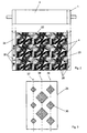
- Fig. 2 shows a practical cylinder layout (32) for the on the printing cylinder (1) grave printing form (3). Multiple positions are positioned in the cylinder layout (32) Single use (4) with between the single use (4) or on an edge (33) of the Cylinder layouts (32) lying test cut areas (26). The other Edge (34) are control and control characters (35) visible on the Printing form (3) should also be engraved.
- Fig. 3 shows a test cut area (26), in which three lying side by side Engraving lines Sample cups (36) were engraved on the engraving line (37) sample cups (36) representing the tonal value "light”, on an engraving line (38) and the sample cups (36) representing the tonal value "depth” the engraving line (39) sample cups (36), which correspond to a "midtone”.
Landscapes
- Engineering & Computer Science (AREA)
- Multimedia (AREA)
- Signal Processing (AREA)
- Manufacture Or Reproduction Of Printing Formes (AREA)
- Editing Of Facsimile Originals (AREA)
Claims (15)
- Procédé de gravure de formes d'impression (3) pour l'impression en taille douce sur un cylindre d'impression (1) dans une machine de gravure électronique, comprenant un organe de gravure (5) recevant un signal de commande de gravure (GS), cet organe gravant ligne par ligne une succession de cuvettes réparties suivant une trame de gravure dans le cylindre d'impression (1), et les dimensions géométriques des cuvettes représentant des valeurs de teintes à graver, selon lequelcaractérisé en ce queon fixe les positions des éléments (4) à graver dans la matrice d'impression (3) par une implantation de cylindre (32) etpendant un segment d'essai produit avant la gravure de la forme d'impression (3), on grave des cuvettes échantillons (36) dans au moins une zone échantillon (26) dans le cylindre d'impression (1) et on exploite les dimensions géométriques pour calibrer le signal de commande de gravure (GS),
pour éviter un positionnement erroné de la zone de segment d'essai (26) sur le cylindre d'impression (1), on détermine la taille et la longueur de la zone de segment d'essai (26) à l'aide de l'implantation de cylindre (32). - Procédé selon la revendication 1,
caractérisé en ce qu'on réalise l'implantation (32) du cylindre par le positionnement des éléments (4) dans un poste de travail (23) en contrôlant visuellement un moniteur (24) etpour une conception de l'implantation (32) du cylindre on marque en même temps la zone d'essai (26) souhaité suivant la taille et la position dans la conception de cylindre (32). - Procédé selon la revendication 2,
caractérisé en ce qu'
on marque la zone d'essai (26) dans la conception de cylindre (32) avec une couleur particulière. - Procédé selon la revendication 2,
caractérisé en ce que
le segment d'essai (26) souhaité est marqué par une couche spéciale dans l'implantation de cylindre (32). - Procédé selon l'une quelconque des revendications 1 à 4,
caractérisé en ce qu'on obtient le signal de commande de gravure (GS) destiné à l'organe de gravure (5) à partir des données de gravure (GD) et à chaque cuvette on associe une donnée de gravure représentant une valeur de teinte entre « lumière » et « profondeur »,on génère les données de gravure (GD) de la forme d'impression (3) à graver à partir des données de gravure (GD') des différents éléments à graver (4) dans la forme d'impression (3), selon l'implantation (32) du cylindre,la zone d'essai (26) marquée dans l'implantation de cylindre (32) est identifiée lorsqu'on génère les données de gravure (GD) eton convertit la zone d'essai (26) identifiée en des données de position correspondantes (PD). - Procédé selon l'une quelconque des revendications 1 à 4,
caractérisé en ce qu'on obtient le signal de commande de gravure (GS) pour l'organe de gravure (5) à partir de données de gravure (GD), et chaque cuvette est associée à une donnée de gravure représentant une valeur de teinte comprise entre « lumière » et « profondeur »,on génère les données de gravure (GD) de la matrice d'impression (3) à graver à partir des données de gravure (GD') des différents éléments (4) à graver dans la forme d'impression (3), selon l'implantation (32) du cylindre,on prédétermine la taille de la zone d'essai (26),on marque la zone d'essai (26) avec la taille prédéterminée par une recherche dans l'état des données de gravure (GD) de la forme d'impression (3) et on marque eton convertit la zone d'essai (26), marquée, en des données de position correspondantes (PD). - Procédé selon l'une quelconque des revendications 5 ou 6,
caractérisé en ce que
les données de position (PD) définissent la position en coordonnées de la zone d'essai (26) dans la forme d'impression (3) sur le cylindre d'impression (1). - Procédé selon l'une quelconque des revendications 5 à 7,
caractérisé en ce qu'
on fournit les données de position (PD) de la machine à graver pour commander la gravure d'essai. - Procédé selon l'une quelconque des revendications 5 à 8,
caractérisé en ce qu'on coulisse l'organe de gravure (5) pour graver en surface dans la direction axiale du cylindre d'impression (1) eton positionne l'organe de gravure (5) avant la gravure d'essai à l'aide des données de position (PD) sur le point de départ de gravure, axial de la zone d'essai (26). - Procédé selon l'une quelconque des revendications 5 à 9,
caractérisé en ce que
les données de position (PD) commandent la gravure de la cuvette échantillon (36) dans la zone d'essai (26) lors de l'essai. - Procédé selon l'une quelconque des revendications 5 ou 6,
caractérisé en ce qu'
on mémorise les données de position (PD) avec les données de gravure (GD) d'une forme d'impression (3) pour les utilisations ultérieures. - Procédé selon l'une quelconque des revendications 1 à 11,
caractérisé en ce que
lors de la gravure d'essai :on grave des cuvettes échantillons (36) pour des valeurs de teintes prédéterminées,on mesure les dimensions réelles géométriques des cuvettes échantillons (36) à graver et on les compare à des dimensions de consignes des valeurs de teintes prédéterminées età partir de la comparaison on forme des valeurs de réglage pour calibrer le signal de commande de gravure. - Procédé selon la revendication 12,
caractérisé en ce qu'
on prédétermine les valeurs de teintes pour « lumière » et « profondeur » pour la gravure échantillon. - Procédé selon la revendication 13,
caractérisé en ce qu'
on prédétermine au moins une « teinte moyenne » en plus pour la gravure échantillon. - Procédé selon l'une quelconque des revendications 12 à 14,
caractérisé en ce que
sur chaque ligne de gravure, dans la zone de segment d'essai (26), on grave au moins une cuvette échantillon (36) par valeur de teinte prédéterminée.
Applications Claiming Priority (3)
| Application Number | Priority Date | Filing Date | Title |
|---|---|---|---|
| DE19805179A DE19805179B4 (de) | 1998-02-10 | 1998-02-10 | Verfahren zur Gravur von Druckformen |
| DE19805179 | 1998-02-10 | ||
| PCT/DE1999/000200 WO1999041078A1 (fr) | 1998-02-10 | 1999-01-27 | Procede pour graver des chassis d'imprimerie |
Publications (2)
| Publication Number | Publication Date |
|---|---|
| EP1054769A1 EP1054769A1 (fr) | 2000-11-29 |
| EP1054769B1 true EP1054769B1 (fr) | 2001-12-19 |
Family
ID=7857137
Family Applications (1)
| Application Number | Title | Priority Date | Filing Date |
|---|---|---|---|
| EP99907285A Expired - Lifetime EP1054769B1 (fr) | 1998-02-10 | 1999-01-27 | Procede pour graver des chassis d'imprimerie |
Country Status (7)
| Country | Link |
|---|---|
| US (1) | US6467405B1 (fr) |
| EP (1) | EP1054769B1 (fr) |
| JP (1) | JP3325882B2 (fr) |
| CN (1) | CN1290210A (fr) |
| DE (2) | DE19805179B4 (fr) |
| ES (1) | ES2168003T3 (fr) |
| WO (1) | WO1999041078A1 (fr) |
Families Citing this family (11)
| Publication number | Priority date | Publication date | Assignee | Title |
|---|---|---|---|---|
| DE19952994B4 (de) * | 1999-11-04 | 2006-05-24 | Hell Gravure Systems Gmbh | Verfahren zur Gravur von Druckzylindern |
| DE19952996A1 (de) | 1999-11-04 | 2001-05-10 | Heidelberger Druckmasch Ag | Gravierorgan für elektronische Graviermaschine |
| DE10012520A1 (de) * | 2000-03-15 | 2001-09-20 | Heidelberger Druckmasch Ag | Verfahren zur Herstellung von Druckzylindern |
| DE10159241B4 (de) * | 2001-12-03 | 2005-05-19 | Hell Gravure Systems Gmbh | Verfahren zur Gravur von Druckformen |
| ATE369977T1 (de) * | 2004-02-27 | 2007-09-15 | Hell Gravure Systems Gmbh & Co | Verfahren zur direkten gravur von näpfchen zur aufnahme von druckfarbe für den tiefdruck |
| US7191529B2 (en) * | 2005-02-15 | 2007-03-20 | Columbia Marking Tools | Apparatus and method for controlling a programmable marking scribe |
| CN103832049B (zh) * | 2014-01-28 | 2015-09-23 | 太仓丽盛制版有限公司 | 凹版制版中二次补充雕刻方法 |
| CN105398196A (zh) * | 2014-09-16 | 2016-03-16 | 上海运青制版有限公司 | 一种刻印产品编号装置 |
| CN111806059B (zh) * | 2020-06-19 | 2022-09-30 | 固高科技股份有限公司 | 驱动方法、装置、电雕控制系统和计算机可读存储介质 |
| CN111907190B (zh) * | 2020-06-19 | 2022-07-15 | 固高科技股份有限公司 | 驱动方法、装置、电雕控制系统和计算机可读存储介质 |
| CN112356559B (zh) * | 2020-11-23 | 2022-05-27 | 固高科技股份有限公司 | 调整网穴位置的雕刻控制方法、装置和电雕控制系统 |
Family Cites Families (14)
| Publication number | Priority date | Publication date | Assignee | Title |
|---|---|---|---|---|
| DE681929C (de) | 1936-06-28 | 1939-10-04 | Siepmann & Co E | Vorrichtung zum Schleifen von Messern, insbesondere von Maehmessern |
| JPS5655948A (en) | 1979-10-12 | 1981-05-16 | Dainippon Screen Mfg Co Ltd | Image collecting method in image scanning recorder |
| JPS57195249A (en) * | 1981-05-27 | 1982-11-30 | Dainippon Screen Mfg Co Ltd | Control method for scanning and recording of reproduced picture |
| DE3687074D1 (de) * | 1985-03-21 | 1992-12-17 | Felix Brunner | Verfahren, regelvorrichtung und hilfsmittel zur erzielung eines gleichfoermigen druckresultats an einer autotypisch arbeitenden mehrfarbenoffsetdruckmaschine. |
| ATE54524T1 (de) * | 1986-04-30 | 1990-07-15 | Hell Rudolf Dr Ing Gmbh | Verfahren zur aufzeichnung von druckformen. |
| US5293426A (en) * | 1990-05-25 | 1994-03-08 | R. R. Donnelley & Sons Company | Printing cylinder engraver calibration system and method |
| CH681929A5 (en) * | 1990-06-08 | 1993-06-15 | Ugra Verein Zur Foerderung Wis | Quality control testing of printing processes - uses test pattern consisting of mixt. of line dot and chess board patterns |
| US5424845A (en) * | 1993-02-25 | 1995-06-13 | Ohio Electronic Engravers, Inc. | Apparatus and method for engraving a gravure printing cylinder |
| US5825503A (en) * | 1993-02-25 | 1998-10-20 | Ohio Electronic Engravers, Inc. | Engraving apparatus and method for adjusting a worn stylus using a midtone correction |
| US5583647A (en) * | 1993-05-05 | 1996-12-10 | Ohio Electronic Engravers, Inc. | Cylinder support apparatus and method for use in an engraver |
| US5402246A (en) * | 1993-07-20 | 1995-03-28 | Ohio Electronic Engravers, Inc. | Method for predicting ink consumption |
| DE19533811A1 (de) * | 1995-09-13 | 1997-03-20 | Heidelberger Druckmasch Ag | Verfahren zum Bebildern eines Druckformträgers für eine Druckmaschine |
| DE19734411A1 (de) * | 1997-08-08 | 1999-02-11 | Heidelberger Druckmasch Ag | Verfahren zum Positionieren von Gravierorganen |
| DE19811637A1 (de) * | 1998-03-18 | 1999-09-23 | Heidelberger Druckmasch Ag | Ermittlung der Nullposition eines Gravierorgans |
-
1998
- 1998-02-10 DE DE19805179A patent/DE19805179B4/de not_active Expired - Fee Related
-
1999
- 1999-01-27 ES ES99907285T patent/ES2168003T3/es not_active Expired - Lifetime
- 1999-01-27 WO PCT/DE1999/000200 patent/WO1999041078A1/fr not_active Ceased
- 1999-01-27 CN CN99802820A patent/CN1290210A/zh active Pending
- 1999-01-27 JP JP2000531307A patent/JP3325882B2/ja not_active Expired - Lifetime
- 1999-01-27 DE DE59900590T patent/DE59900590D1/de not_active Expired - Fee Related
- 1999-01-27 EP EP99907285A patent/EP1054769B1/fr not_active Expired - Lifetime
- 1999-01-27 US US09/601,487 patent/US6467405B1/en not_active Expired - Fee Related
Also Published As
| Publication number | Publication date |
|---|---|
| JP3325882B2 (ja) | 2002-09-17 |
| CN1290210A (zh) | 2001-04-04 |
| US6467405B1 (en) | 2002-10-22 |
| ES2168003T3 (es) | 2002-05-16 |
| DE59900590D1 (de) | 2002-01-31 |
| DE19805179B4 (de) | 2005-03-10 |
| WO1999041078A1 (fr) | 1999-08-19 |
| EP1054769A1 (fr) | 2000-11-29 |
| DE19805179A1 (de) | 1999-08-12 |
| JP2002502738A (ja) | 2002-01-29 |
Similar Documents
| Publication | Publication Date | Title |
|---|---|---|
| EP0986465B1 (fr) | Procede de gravure de cylindres d'impression | |
| EP1001882B1 (fr) | Procede de positionnement d'organes de gravure | |
| EP1054769A1 (fr) | Procede pour graver des chassis d'imprimerie | |
| EP0986466B1 (fr) | Procede pour produire et evaluer une decoupe d'echantillon | |
| DE3129649C2 (fr) | ||
| DE10116672A1 (de) | Verfahren und Vorrichtung zur Materialbearbeitung | |
| EP0966353B1 (fr) | Procede et dispositif de gravure de cylindres d'impression | |
| DE19947397B4 (de) | Verfahren zur nahtlosen Gravur von Mustern | |
| DE102015009950B4 (de) | Verfahren und Vorrichtung zur Erzeugung eines Druckbildes auf einem Druckformrohling | |
| DE19814939A1 (de) | Verfahren zum Positionieren von Gravierorganen | |
| EP1386727B1 (fr) | Procédé pour améliorer la qualité d'une image gravée dans un cylindre d'impression | |
| WO2000008842A1 (fr) | Procede pour produire et evaluer une decoupe d'echantillon | |
| EP2058122B1 (fr) | Procédé et dispositif destinés à la gravure de cylindres d'impression | |
| DE4221482C2 (de) | Verfahren zur Lagekontrolle eines Druckbildes auf einer Druckform | |
| DE10010904A1 (de) | Verfahren zur Gravur von Druckzylindern | |
| EP1049580B1 (fr) | Procede d'etalonnage d'un amplificateur de gravure | |
| EP1069989B1 (fr) | Procede de gravure de formes d'impression | |
| WO2000066362A2 (fr) | Procede pour faire fonctionner une machine a graver | |
| DE19733442A1 (de) | Verfahren und Einrichtung zur Gravur von Druckformen | |
| DE10012520A1 (de) | Verfahren zur Herstellung von Druckzylindern | |
| DE102009004215A1 (de) | Verfahren und Vorrichtung zur Kontrolle der Qualität einer Druckform | |
| DE10159241B4 (de) | Verfahren zur Gravur von Druckformen | |
| WO2000015434A1 (fr) | Procede de gravure de cylindres d'impression | |
| DE102010056306B4 (de) | Verfahren zur Gravur von Strukturen in eine Oberfläche eines Zylinders | |
| DE19841818A1 (de) | Verfahren zum Positionieren von Gravierorganen |
Legal Events
| Date | Code | Title | Description |
|---|---|---|---|
| PUAI | Public reference made under article 153(3) epc to a published international application that has entered the european phase |
Free format text: ORIGINAL CODE: 0009012 |
|
| 17P | Request for examination filed |
Effective date: 20000911 |
|
| AK | Designated contracting states |
Kind code of ref document: A1 Designated state(s): BE DE ES FR GB IT NL |
|
| RIC1 | Information provided on ipc code assigned before grant |
Free format text: 7B 41C 1/045 A, 7H 04N 1/387 B, 7H 04N 1/407 B |
|
| RIC1 | Information provided on ipc code assigned before grant |
Free format text: 7B 41C 1/045 A, 7H 04N 1/387 B, 7H 04N 1/407 B |
|
| GRAG | Despatch of communication of intention to grant |
Free format text: ORIGINAL CODE: EPIDOS AGRA |
|
| GRAG | Despatch of communication of intention to grant |
Free format text: ORIGINAL CODE: EPIDOS AGRA |
|
| GRAH | Despatch of communication of intention to grant a patent |
Free format text: ORIGINAL CODE: EPIDOS IGRA |
|
| 17Q | First examination report despatched |
Effective date: 20010523 |
|
| GRAH | Despatch of communication of intention to grant a patent |
Free format text: ORIGINAL CODE: EPIDOS IGRA |
|
| GRAA | (expected) grant |
Free format text: ORIGINAL CODE: 0009210 |
|
| AK | Designated contracting states |
Kind code of ref document: B1 Designated state(s): BE DE ES FR GB IT NL |
|
| REG | Reference to a national code |
Ref country code: GB Ref legal event code: IF02 |
|
| PG25 | Lapsed in a contracting state [announced via postgrant information from national office to epo] |
Ref country code: ES Free format text: LAPSE BECAUSE OF NON-PAYMENT OF DUE FEES Effective date: 20020128 |
|
| PG25 | Lapsed in a contracting state [announced via postgrant information from national office to epo] |
Ref country code: BE Free format text: LAPSE BECAUSE OF NON-PAYMENT OF DUE FEES Effective date: 20020131 |
|
| REF | Corresponds to: |
Ref document number: 59900590 Country of ref document: DE Date of ref document: 20020131 |
|
| GBT | Gb: translation of ep patent filed (gb section 77(6)(a)/1977) |
Effective date: 20020322 |
|
| REG | Reference to a national code |
Ref country code: ES Ref legal event code: FG2A Ref document number: 2168003 Country of ref document: ES Kind code of ref document: T3 |
|
| ET | Fr: translation filed | ||
| BERE | Be: lapsed |
Owner name: HEIDELBERGER DRUCKMASCHINEN A.G. Effective date: 20020131 |
|
| PLBE | No opposition filed within time limit |
Free format text: ORIGINAL CODE: 0009261 |
|
| STAA | Information on the status of an ep patent application or granted ep patent |
Free format text: STATUS: NO OPPOSITION FILED WITHIN TIME LIMIT |
|
| PG25 | Lapsed in a contracting state [announced via postgrant information from national office to epo] |
Ref country code: FR Free format text: LAPSE BECAUSE OF NON-PAYMENT OF DUE FEES Effective date: 20021129 |
|
| 26N | No opposition filed | ||
| REG | Reference to a national code |
Ref country code: FR Ref legal event code: ST |
|
| PG25 | Lapsed in a contracting state [announced via postgrant information from national office to epo] |
Ref country code: GB Free format text: LAPSE BECAUSE OF NON-PAYMENT OF DUE FEES Effective date: 20030127 |
|
| PG25 | Lapsed in a contracting state [announced via postgrant information from national office to epo] |
Ref country code: NL Free format text: LAPSE BECAUSE OF NON-PAYMENT OF DUE FEES Effective date: 20030801 |
|
| GBPC | Gb: european patent ceased through non-payment of renewal fee | ||
| NLV4 | Nl: lapsed or anulled due to non-payment of the annual fee |
Effective date: 20030801 |
|
| REG | Reference to a national code |
Ref country code: ES Ref legal event code: FD2A Effective date: 20030211 |
|
| PG25 | Lapsed in a contracting state [announced via postgrant information from national office to epo] |
Ref country code: IT Free format text: LAPSE BECAUSE OF NON-PAYMENT OF DUE FEES Effective date: 20050127 |
|
| PG25 | Lapsed in a contracting state [announced via postgrant information from national office to epo] |
Ref country code: FR Free format text: LAPSE BECAUSE OF NON-PAYMENT OF DUE FEES Effective date: 20020131 |
|
| PGFP | Annual fee paid to national office [announced via postgrant information from national office to epo] |
Ref country code: DE Payment date: 20090131 Year of fee payment: 11 |
|
| PG25 | Lapsed in a contracting state [announced via postgrant information from national office to epo] |
Ref country code: DE Free format text: LAPSE BECAUSE OF NON-PAYMENT OF DUE FEES Effective date: 20100803 |