EP1054830B1 - Verfahren zum aufwickeln einer bahn - Google Patents
Verfahren zum aufwickeln einer bahn Download PDFInfo
- Publication number
- EP1054830B1 EP1054830B1 EP99902561A EP99902561A EP1054830B1 EP 1054830 B1 EP1054830 B1 EP 1054830B1 EP 99902561 A EP99902561 A EP 99902561A EP 99902561 A EP99902561 A EP 99902561A EP 1054830 B1 EP1054830 B1 EP 1054830B1
- Authority
- EP
- European Patent Office
- Prior art keywords
- roll
- support members
- measurement
- web
- relative positions
- Prior art date
- Legal status (The legal status is an assumption and is not a legal conclusion. Google has not performed a legal analysis and makes no representation as to the accuracy of the status listed.)
- Expired - Lifetime
Links
- 238000004804 winding Methods 0.000 title claims abstract description 30
- 238000000034 method Methods 0.000 title claims abstract description 27
- 238000005259 measurement Methods 0.000 claims abstract description 23
- 230000001105 regulatory effect Effects 0.000 claims abstract description 15
- 230000007547 defect Effects 0.000 claims abstract 2
- 239000010410 layer Substances 0.000 description 6
- 230000000694 effects Effects 0.000 description 3
- 239000002344 surface layer Substances 0.000 description 2
- 239000000725 suspension Substances 0.000 description 2
- 238000000418 atomic force spectrum Methods 0.000 description 1
- 230000015572 biosynthetic process Effects 0.000 description 1
- 238000002604 ultrasonography Methods 0.000 description 1
Images



Classifications
-
- B—PERFORMING OPERATIONS; TRANSPORTING
- B65—CONVEYING; PACKING; STORING; HANDLING THIN OR FILAMENTARY MATERIAL
- B65H—HANDLING THIN OR FILAMENTARY MATERIAL, e.g. SHEETS, WEBS, CABLES
- B65H23/00—Registering, tensioning, smoothing or guiding webs
- B65H23/02—Registering, tensioning, smoothing or guiding webs transversely
- B65H23/032—Controlling transverse register of web
- B65H23/0328—Controlling transverse register of web by moving the winding device
-
- B—PERFORMING OPERATIONS; TRANSPORTING
- B65—CONVEYING; PACKING; STORING; HANDLING THIN OR FILAMENTARY MATERIAL
- B65H—HANDLING THIN OR FILAMENTARY MATERIAL, e.g. SHEETS, WEBS, CABLES
- B65H18/00—Winding webs
- B65H18/02—Supporting web roll
- B65H18/06—Lateral-supporting
-
- B—PERFORMING OPERATIONS; TRANSPORTING
- B65—CONVEYING; PACKING; STORING; HANDLING THIN OR FILAMENTARY MATERIAL
- B65H—HANDLING THIN OR FILAMENTARY MATERIAL, e.g. SHEETS, WEBS, CABLES
- B65H2301/00—Handling processes for sheets or webs
- B65H2301/40—Type of handling process
- B65H2301/41—Winding, unwinding
- B65H2301/414—Winding
- B65H2301/4148—Winding slitting
-
- B—PERFORMING OPERATIONS; TRANSPORTING
- B65—CONVEYING; PACKING; STORING; HANDLING THIN OR FILAMENTARY MATERIAL
- B65H—HANDLING THIN OR FILAMENTARY MATERIAL, e.g. SHEETS, WEBS, CABLES
- B65H2405/00—Parts for holding the handled material
- B65H2405/40—Holders, supports for rolls
- B65H2405/42—Supports for rolls fully removable from the handling machine
- B65H2405/422—Trolley, cart, i.e. support movable on floor
-
- B—PERFORMING OPERATIONS; TRANSPORTING
- B65—CONVEYING; PACKING; STORING; HANDLING THIN OR FILAMENTARY MATERIAL
- B65H—HANDLING THIN OR FILAMENTARY MATERIAL, e.g. SHEETS, WEBS, CABLES
- B65H2511/00—Dimensions; Position; Numbers; Identification; Occurrences
- B65H2511/10—Size; Dimensions
- B65H2511/16—Irregularities, e.g. protuberances
-
- B—PERFORMING OPERATIONS; TRANSPORTING
- B65—CONVEYING; PACKING; STORING; HANDLING THIN OR FILAMENTARY MATERIAL
- B65H—HANDLING THIN OR FILAMENTARY MATERIAL, e.g. SHEETS, WEBS, CABLES
- B65H2515/00—Physical entities not provided for in groups B65H2511/00 or B65H2513/00
- B65H2515/30—Forces; Stresses
Definitions
- the web is wound onto a spool on support of a support roll and through the nip formed between the support roll and the roll that is being produced.
- the spool is supported at least partly by means of a support member fitted in the centre of the spool.
- the spool and the roll are supported and/or loaded by means of a device whose position can be varied.
- the loading and support units of said device are shifted substantially in a plane passing through the axes of the support roll and of the roll that is being produced in order to load and/or to support the roll that is being produced in the winding position.
- the method in accordance with the invention can be utilized in all such winding methods in which the direction of arrival of the web to be wound onto the roll can be regulated in relation to the axis of the roll or in which the winding is carried out by means of a winding nip in which the distribution of loading in the direction of width of the nip can be regulated.
- the method is also suitable for nip-free centre-drive winding in which the tension of the web on the roll is regulated exclusively by means of the torque of rotation applied to the shaft of the web roll.
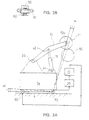
- Fig. 1 is a schematic axonometric view
- Fig. 2 a side view of a centre-drive winder.
- Figs. 1 and 2 also illustrate a mode in accordance with the present invention for regulation of the nip line between the roll 11 that is being formed and the support roll 50 in the centre-drive winder.
- a centre-drive winder is understood in particular as a winder type used in connection with a slitter-winder, in which the rolls formed out of component webs are supported, each of them separately, from the ends of their roll spools and at least from one point at the side of the web roll by means of a support roll or an equivalent support member.
- a second loading cylinder 17 has been attached from one of its ends by means of an articulated joint.
- the other end of the first loading cylinder 16 has been attached by means of an articulated joint 41 to the first sledge 14, and the other end of the second loading cylinder 17 has been attached similarly by means of an articulated joint to the second sledge 15.
- a first force metering detector 20 has been fitted, and similarly, in connection with the second sledge 15, a second force metering detector 21 has been fitted.
- the force metering detectors 20,21 can be placed, for example, between the sledges 14,15 and their brakes. Alternatively, the force metering detectors 20,21 can be placed in connection with the support seats of the roll 11 that is being formed.
- the force metering detectors 20.21 meter the force acting in the direction of the axis of the roll spool, which force is transferred from the roll spool to the winding arms 12,13 and further to the sledges 14,15.
- the support point 12a of the roll 11 on the support arm 12 attached to the sledge 14 is shifted by the angle ⁇ , and when the other sledge 15 remains stationary, the direction of the axis of the roll 11 is altered in relation to the running direction of the web that is being fed onto the roll, and the axial force in the interior of the roil 11 is compensated for, in which case formation of an error of shape in the roll 11 is prevented.
- the nip lines N 1 and N 2 come together, and at the roll 11 end that is shifted the nip lines N 1 and N 2 are placed at the distance ⁇ x from one another.
- axial shifting of the web wound onto the roll 11 can be prevented, so that the ends of the roll 11 to be wound become planar.
- the side plane of the roll 11 can also be measured directly, e.g., by means of photocells, an ultrasound detector, or by means of capacitive or contact measurement.
- said metering of lateral forces is, however, preferable, because by its means it is possible to see considerably earlier indirectly when such a force arising from the winding nip or from profile errors in the web is applied to the rell 11 as attempts to divert the web layers to be wound onto the roll 11 from their desired position, and measures of correction can be initiated earlier.
Landscapes
- Replacement Of Web Rolls (AREA)
- Winding Of Webs (AREA)
- Sanitary Thin Papers (AREA)
- Registering, Tensioning, Guiding Webs, And Rollers Therefor (AREA)
- Control Of Vehicles With Linear Motors And Vehicles That Are Magnetically Levitated (AREA)
- Train Traffic Observation, Control, And Security (AREA)
- Transition And Organic Metals Composition Catalysts For Addition Polymerization (AREA)
- Mechanical Operated Clutches (AREA)
- Control Of Combustion (AREA)
Claims (10)
- Verfahren beim Aufwickeln einer Bahn, wobei
die auszubildende Rolle (11) in der Richtung der Achse der Rolle (11) mittels eines ersten Stützelementes (12) und eines zweiten Stützelementes (13) gestützt ist, die an beiden Seiten der Rolle (11) angeordnet sind,
dadurch gekennzeichnet, dass
die Form des Endes der auszubildenden Rolle (11) mittels einer indirekten oder einer direkten Messung gemessen wird und die Relativpositionen der Stützelemente (12, 13) in Bezug aufeinander auf der Grundlage der Messung eingestellt werden, wobei in diesem Zusammenhang jegliche Formfehler bei den Enden der auszubildenden Rolle (11) verhindert werden können. - Verfahren gemäss Anspruch 1,
dadurch gekennzeichnet, dass
als ein indirektes Messverfahren die in der axialen Richtung der auszubildenden Rolle (11) aufgebrachte Kraft zumindest in Verbindung mit dem Stützelement (12, 13) gemessen wird, das ein Ende der Rolle stützt, und die Relativpositionen der Stützelemente (12, 13) auf der Grundlage dieser Messung eingestellt werden. - Verfahren gemäss Anspruch 1,
dadurch gekennzeichnet, dass
die auf die auszubildende Rolle (11) aufgebrachte Axialkraft in Verbindung mit den Stützelementen (12, 13) an beiden Enden der Rolle gemessen wird, und die Relativpositionen der Stützelemente (12, 13) auf der Grundlage dieser Messung eingestellt werden. - Verfahren gemäss Anspruch 3,
dadurch gekennzeichnet, dass
die Resultierende der auf die auszubildende Rolle (11) aufgebrachten Kräfte als die Differenz zwischen den gemessenen Stützkräften bestimmt wird und die Relativpositionen (12, 13) der Stützelemente auf der Grundlage dieser Messung eingestellt werden. - Verfahren gemäss einem der Ansprüche 1 bis 4,
dadurch gekennzeichnet, dass
die Relativpositionen der Stützelemente (12, 13) der auszubildenden Rolle (11) auf der Grundlage der Daten eingestellt werden, die von dem Messen erhalten werden, indem die auf die auszubildende Rolle (11) durch ein Stützelement (12, 13) aufgebrachte Last erhöht wird oder verringert wird. - Verfahren gemäss einem der Ansprüche 1 bis 5,
dadurch gekennzeichnet, dass
die Relativpositionen der Stützelemente (12, 13) der auszubildenden Rolle (11) auf der Grundlage der Daten eingestellt werden, die von dem Messen erhalten werden, indem einen der Stützelemente (12, 13) so verschoben wird, dass die Laufrichtung der von der Seite der auszubildenden Rolle (11) tretenden Bahn in Bezug auf die Achse der auszubildenden Rolle (11) verändert wird. - Verfahren gemäss Anspruch,
dadurch gekennzeichnet, dass
der Ort der Bahnlagen, die die obersten Lagen sind, zu jedem speziellen Zeitpunkt an der auszubildenden Rolle (11) in der axialen Richtung der Rolle (11) mittels eines kontaktfreien Messverfahrens gemessen wird und die Relativpositionen der Stützelemente (12, 13) auf der Grundlage dieser Messung eingestellt werden, - Verfahren gemäss Anspruch 1,
dadurch gekennzeichnet, dass
der Ort der Bahnlagen, die die obersten Lagen sind, zu jedem speziellen Zeitpunkt an der auszubildenden Rolle (11) in der Axialrichtung der Rolle (11) mittels eines Kontaktmessverfahrens gemessen wird und die Relativpositionen der Stützelemente (12, 13) auf der Grundlage dieser Messung eingestellt werden. - Verfahren gemäss 7 oder 8,
dadurch gekennzeichnet, dass
die Relativpositionen der Stützelemente (12, 13) der auszubildenden Rolle (11) auf der Grundlage von den Daten eingestellt werden, die von der Messung erhalten werden, indem die durch eines der Stützelemente auf die auszubildende Rolle (11) aufgebrachte Last erhöht wird oder verringert wird. - Verfahren gemäss einem der Ansprüche 7 bis 9,
dadurch gekennzeichnet, dass
die Relativpositionen der Stützelemente (12, 13) der auszubildenden Rolle (11) auf der Grundlage der Daten eingestellt werden, die von der Messung erhalten werden, indem eines der Stützelemente (12, 13) so verschoben wird, dass die Laufrichtung der zu der Seite der auszubildenden Rolle (11) tretenden Bahn in Bezug auf die Achse der auszubildenden Rolle (11) verändert wird.
Applications Claiming Priority (3)
| Application Number | Priority Date | Filing Date | Title |
|---|---|---|---|
| FI980252 | 1998-02-04 | ||
| FI980252A FI106446B (fi) | 1998-02-04 | 1998-02-04 | Menetelmä rainan rullauksessa |
| PCT/FI1999/000070 WO1999040003A1 (en) | 1998-02-04 | 1999-02-02 | Method in winding of a web |
Publications (2)
| Publication Number | Publication Date |
|---|---|
| EP1054830A1 EP1054830A1 (de) | 2000-11-29 |
| EP1054830B1 true EP1054830B1 (de) | 2002-05-22 |
Family
ID=8550703
Family Applications (1)
| Application Number | Title | Priority Date | Filing Date |
|---|---|---|---|
| EP99902561A Expired - Lifetime EP1054830B1 (de) | 1998-02-04 | 1999-02-02 | Verfahren zum aufwickeln einer bahn |
Country Status (9)
| Country | Link |
|---|---|
| US (1) | US6095452A (de) |
| EP (1) | EP1054830B1 (de) |
| JP (1) | JP4328017B2 (de) |
| AT (1) | ATE217850T1 (de) |
| AU (1) | AU2280699A (de) |
| DE (1) | DE69901540T2 (de) |
| FI (1) | FI106446B (de) |
| NO (1) | NO316219B1 (de) |
| WO (1) | WO1999040003A1 (de) |
Families Citing this family (8)
| Publication number | Priority date | Publication date | Assignee | Title |
|---|---|---|---|---|
| KR100374668B1 (ko) * | 1998-03-26 | 2003-03-04 | 가와사끼 세이데쓰 가부시키가이샤 | 금속박의 권취방법 및 권취장치 |
| FI107908B (fi) * | 1998-11-04 | 2001-10-31 | Metso Paper Inc | Menetelmä ja laitteisto rullan rakenteen hallitsemiseksi |
| FI105803B (fi) * | 1999-03-30 | 2000-10-13 | Valmet Corp | Menetelmä ja laitteisto paperirullan jatkuvatoimisessa aukirullauksessa |
| US6669818B2 (en) * | 2000-06-28 | 2003-12-30 | Metso Paper Karlstad Ab | Shortened layout from dryer to reel in tissue machine |
| DE10234958A1 (de) * | 2002-07-31 | 2004-02-12 | Voith Paper Patent Gmbh | Verfahren zum Überführen eines Aufführstreifens einer Materialbahn auf eine Wickelvorrichtung |
| DE10250863B4 (de) * | 2002-10-31 | 2005-06-02 | Brückner Maschinenbau GmbH | Wickelvorrichtung für bahnförmige Materialien, insbesondere Kunststofffolien |
| DE10327245A1 (de) * | 2003-06-17 | 2005-01-05 | Voith Paper Patent Gmbh | Aufwickelvorrichtung |
| JP4982313B2 (ja) * | 2007-09-20 | 2012-07-25 | リョービ株式会社 | 転写用フィルムの巻取り方法及び印刷用紙への転写装置 |
Family Cites Families (11)
| Publication number | Priority date | Publication date | Assignee | Title |
|---|---|---|---|---|
| DE1219576B (de) * | 1962-12-10 | 1966-06-23 | Continental Elektro Ind Ag | Einrichtung zur Regelung der Bandmittenlage bandfoermiger Wickelgueter |
| US3570735A (en) * | 1968-11-18 | 1971-03-16 | Gpe Controls Inc | Method and apparatus of guiding moving webs |
| JPS5221139B1 (de) * | 1971-05-27 | 1977-06-08 | ||
| US4500045A (en) * | 1983-08-29 | 1985-02-19 | Xerox Corporation | Laterally translatable roll apparatus |
| JPS6242378A (ja) * | 1985-08-19 | 1987-02-24 | Fuji Photo Film Co Ltd | 磁気テ−プ巻込方法および装置 |
| DE3721969C2 (de) * | 1987-07-03 | 1994-02-10 | Reifenhaeuser Masch | Vorrichtung zum Aufwickeln einer Folienbahn, insbes. einer Kunststoffolienbahn, zu einem Folienwickel auf einem Wickelkern |
| DE3924612A1 (de) * | 1989-07-26 | 1991-01-31 | Jagenberg Ag | Tragwalzen-wickelmaschine zum aufwickeln von materialbahnen |
| DE4232363C2 (de) * | 1992-09-26 | 1995-11-30 | Kloeckner Er We Pa Gmbh | Vorrichtung zum kontinuierlichen Wickeln von Materialbahnen |
| DE4408863C2 (de) * | 1994-03-16 | 1998-07-09 | Kampf Gmbh & Co Maschf | Vorrichtung zum Aufwickeln einer Warenbahn, insbesondere Kunststoffolienbahn |
| FI100467B (fi) * | 1994-05-26 | 1997-12-15 | Valmet Corp | Menetelmä ja laite rainan rullauksessa |
| EP0919499B1 (de) * | 1997-11-29 | 2003-07-02 | Meinan Machinery Works, Inc. | Aufwickelvorrichtung für Furnier |
-
1998
- 1998-02-04 FI FI980252A patent/FI106446B/fi not_active IP Right Cessation
-
1999
- 1999-01-11 US US09/227,808 patent/US6095452A/en not_active Expired - Lifetime
- 1999-02-02 AT AT99902561T patent/ATE217850T1/de active
- 1999-02-02 JP JP2000530443A patent/JP4328017B2/ja not_active Expired - Fee Related
- 1999-02-02 EP EP99902561A patent/EP1054830B1/de not_active Expired - Lifetime
- 1999-02-02 AU AU22806/99A patent/AU2280699A/en not_active Abandoned
- 1999-02-02 DE DE69901540T patent/DE69901540T2/de not_active Expired - Lifetime
- 1999-02-02 WO PCT/FI1999/000070 patent/WO1999040003A1/en not_active Ceased
-
2000
- 2000-07-14 NO NO20003623A patent/NO316219B1/no not_active IP Right Cessation
Also Published As
| Publication number | Publication date |
|---|---|
| FI980252A0 (fi) | 1998-02-04 |
| JP2002502786A (ja) | 2002-01-29 |
| NO20003623D0 (no) | 2000-07-14 |
| DE69901540D1 (de) | 2002-06-27 |
| EP1054830A1 (de) | 2000-11-29 |
| US6095452A (en) | 2000-08-01 |
| DE69901540T2 (de) | 2002-11-21 |
| AU2280699A (en) | 1999-08-23 |
| FI980252L (fi) | 1999-08-05 |
| ATE217850T1 (de) | 2002-06-15 |
| WO1999040003A1 (en) | 1999-08-12 |
| NO20003623L (no) | 2000-09-27 |
| FI106446B (fi) | 2001-02-15 |
| JP4328017B2 (ja) | 2009-09-09 |
| NO316219B1 (no) | 2003-12-29 |
Similar Documents
| Publication | Publication Date | Title |
|---|---|---|
| EP0642460B1 (de) | Lastfühleranordnung für eine aufwickelvorrichtung | |
| CA2060468C (en) | Method and apparatus for winding a traveling web | |
| US4746076A (en) | Winder device | |
| CA2319573C (en) | Method and apparatus in reeling of a web | |
| CA2147764C (en) | Web-winding process and device | |
| KR100309577B1 (ko) | 웨브의권취장치 | |
| RU2391169C1 (ru) | Способ и устройство для намотки металлических лент на навивочную оправку | |
| CA2128533C (en) | Diameter and lateral position sensitive nip pressure controls in a paper winding system | |
| FI118594B (fi) | Rullain, jossa on kohotettu puolan kannatuskisko | |
| CA2054250C (en) | Reel-up and method for regulation of the nip pressure in a reel-up | |
| US6089496A (en) | Web tension control system for a winding structure | |
| US6095452A (en) | Method and arrangement for winding a web | |
| US2984429A (en) | Single rollstand web handling machine | |
| US5154367A (en) | Web winder having driven cams to relieve roller pressure | |
| KR100430127B1 (ko) | 종이의 중심권취 방법 및 장치 | |
| CA2804641C (en) | Method and device for winding of fiber webs, especially of partial paper and board webs | |
| FI121228B (fi) | Menetelmä paperi- tai kartonkirainan rullauksessa ja kiinnirullain | |
| FI108429B (fi) | Painotelarullain | |
| CA2306467C (en) | Paper web treatment control system based on energy supplied to a bearing | |
| EP1360132B1 (de) | Verfahren und vorrichtung zum aufwickeln einer papier- oder kartonbahn | |
| US6427940B1 (en) | Method and device in winding of a web | |
| US20090189008A1 (en) | Reel-Up and Also a Method and Measuring Unit in Such a Reel-Up | |
| FI20255140A1 (en) | Rolling machine with diameter profile measuring system and diameter profile measuring procedure | |
| FI119633B (fi) | Menetelmä ja laite kuiturainan rullaimessa | |
| HK1186164A (en) | Winding machine and method for controlling the same |
Legal Events
| Date | Code | Title | Description |
|---|---|---|---|
| PUAI | Public reference made under article 153(3) epc to a published international application that has entered the european phase |
Free format text: ORIGINAL CODE: 0009012 |
|
| 17P | Request for examination filed |
Effective date: 20000731 |
|
| AK | Designated contracting states |
Kind code of ref document: A1 Designated state(s): AT DE FR GB IT SE |
|
| GRAG | Despatch of communication of intention to grant |
Free format text: ORIGINAL CODE: EPIDOS AGRA |
|
| 17Q | First examination report despatched |
Effective date: 20010328 |
|
| GRAG | Despatch of communication of intention to grant |
Free format text: ORIGINAL CODE: EPIDOS AGRA |
|
| GRAH | Despatch of communication of intention to grant a patent |
Free format text: ORIGINAL CODE: EPIDOS IGRA |
|
| RAP1 | Party data changed (applicant data changed or rights of an application transferred) |
Owner name: METSO PAPER, INC. |
|
| GRAH | Despatch of communication of intention to grant a patent |
Free format text: ORIGINAL CODE: EPIDOS IGRA |
|
| GRAA | (expected) grant |
Free format text: ORIGINAL CODE: 0009210 |
|
| REF | Corresponds to: |
Ref document number: 217850 Country of ref document: AT Date of ref document: 20020615 Kind code of ref document: T |
|
| REG | Reference to a national code |
Ref country code: GB Ref legal event code: FG4D |
|
| REF | Corresponds to: |
Ref document number: 69901540 Country of ref document: DE Date of ref document: 20020627 |
|
| ET | Fr: translation filed | ||
| PLBE | No opposition filed within time limit |
Free format text: ORIGINAL CODE: 0009261 |
|
| STAA | Information on the status of an ep patent application or granted ep patent |
Free format text: STATUS: NO OPPOSITION FILED WITHIN TIME LIMIT |
|
| 26N | No opposition filed |
Effective date: 20030225 |
|
| PGFP | Annual fee paid to national office [announced via postgrant information from national office to epo] |
Ref country code: GB Payment date: 20090219 Year of fee payment: 11 |
|
| PGFP | Annual fee paid to national office [announced via postgrant information from national office to epo] |
Ref country code: FR Payment date: 20090213 Year of fee payment: 11 |
|
| GBPC | Gb: european patent ceased through non-payment of renewal fee |
Effective date: 20100202 |
|
| REG | Reference to a national code |
Ref country code: FR Ref legal event code: ST Effective date: 20101029 |
|
| PG25 | Lapsed in a contracting state [announced via postgrant information from national office to epo] |
Ref country code: FR Free format text: LAPSE BECAUSE OF NON-PAYMENT OF DUE FEES Effective date: 20100301 |
|
| PG25 | Lapsed in a contracting state [announced via postgrant information from national office to epo] |
Ref country code: GB Free format text: LAPSE BECAUSE OF NON-PAYMENT OF DUE FEES Effective date: 20100202 |
|
| PGFP | Annual fee paid to national office [announced via postgrant information from national office to epo] |
Ref country code: IT Payment date: 20120224 Year of fee payment: 14 |
|
| PGFP | Annual fee paid to national office [announced via postgrant information from national office to epo] |
Ref country code: SE Payment date: 20130219 Year of fee payment: 15 Ref country code: DE Payment date: 20130219 Year of fee payment: 15 |
|
| PGFP | Annual fee paid to national office [announced via postgrant information from national office to epo] |
Ref country code: AT Payment date: 20130213 Year of fee payment: 15 |
|
| REG | Reference to a national code |
Ref country code: DE Ref legal event code: R119 Ref document number: 69901540 Country of ref document: DE |
|
| REG | Reference to a national code |
Ref country code: SE Ref legal event code: EUG |
|
| REG | Reference to a national code |
Ref country code: AT Ref legal event code: MM01 Ref document number: 217850 Country of ref document: AT Kind code of ref document: T Effective date: 20140202 |
|
| PG25 | Lapsed in a contracting state [announced via postgrant information from national office to epo] |
Ref country code: AT Free format text: LAPSE BECAUSE OF NON-PAYMENT OF DUE FEES Effective date: 20140202 Ref country code: SE Free format text: LAPSE BECAUSE OF NON-PAYMENT OF DUE FEES Effective date: 20140203 |
|
| REG | Reference to a national code |
Ref country code: DE Ref legal event code: R119 Ref document number: 69901540 Country of ref document: DE Effective date: 20140902 |
|
| PG25 | Lapsed in a contracting state [announced via postgrant information from national office to epo] |
Ref country code: DE Free format text: LAPSE BECAUSE OF NON-PAYMENT OF DUE FEES Effective date: 20140902 |
|
| PG25 | Lapsed in a contracting state [announced via postgrant information from national office to epo] |
Ref country code: IT Free format text: LAPSE BECAUSE OF NON-PAYMENT OF DUE FEES Effective date: 20140202 |