EP1054833B1 - Fahrbare arbeitsmaschine mit stützbeinen und achsarretierung - Google Patents
Fahrbare arbeitsmaschine mit stützbeinen und achsarretierung Download PDFInfo
- Publication number
- EP1054833B1 EP1054833B1 EP98964499A EP98964499A EP1054833B1 EP 1054833 B1 EP1054833 B1 EP 1054833B1 EP 98964499 A EP98964499 A EP 98964499A EP 98964499 A EP98964499 A EP 98964499A EP 1054833 B1 EP1054833 B1 EP 1054833B1
- Authority
- EP
- European Patent Office
- Prior art keywords
- spring
- working machine
- mobile working
- machine according
- blocking
- Prior art date
- Legal status (The legal status is an assumption and is not a legal conclusion. Google has not performed a legal analysis and makes no representation as to the accuracy of the status listed.)
- Expired - Lifetime
Links
- 230000000903 blocking effect Effects 0.000 title claims description 31
- 230000007246 mechanism Effects 0.000 claims description 21
- 238000004873 anchoring Methods 0.000 claims description 4
- 230000000694 effects Effects 0.000 claims description 3
- 238000000034 method Methods 0.000 description 7
- 230000008569 process Effects 0.000 description 7
- 239000000725 suspension Substances 0.000 description 4
- 230000009471 action Effects 0.000 description 3
- 239000000463 material Substances 0.000 description 3
- 238000010276 construction Methods 0.000 description 2
- 238000006073 displacement reaction Methods 0.000 description 2
- 238000005086 pumping Methods 0.000 description 2
- 230000008901 benefit Effects 0.000 description 1
- 230000001419 dependent effect Effects 0.000 description 1
- 238000011161 development Methods 0.000 description 1
- 230000018109 developmental process Effects 0.000 description 1
- 230000009467 reduction Effects 0.000 description 1
- 230000001960 triggered effect Effects 0.000 description 1
Images


Classifications
-
- B—PERFORMING OPERATIONS; TRANSPORTING
- B66—HOISTING; LIFTING; HAULING
- B66C—CRANES; LOAD-ENGAGING ELEMENTS OR DEVICES FOR CRANES, CAPSTANS, WINCHES, OR TACKLES
- B66C23/00—Cranes comprising essentially a beam, boom, or triangular structure acting as a cantilever and mounted for translatory of swinging movements in vertical or horizontal planes or a combination of such movements, e.g. jib-cranes, derricks, tower cranes
- B66C23/62—Constructional features or details
- B66C23/72—Counterweights or supports for balancing lifting couples
- B66C23/78—Supports, e.g. outriggers, for mobile cranes
- B66C23/80—Supports, e.g. outriggers, for mobile cranes hydraulically actuated
-
- B—PERFORMING OPERATIONS; TRANSPORTING
- B60—VEHICLES IN GENERAL
- B60G—VEHICLE SUSPENSION ARRANGEMENTS
- B60G17/00—Resilient suspensions having means for adjusting the spring or vibration-damper characteristics, for regulating the distance between a supporting surface and a sprung part of vehicle or for locking suspension during use to meet varying vehicular or surface conditions, e.g. due to speed or load
- B60G17/005—Suspension locking arrangements
-
- B—PERFORMING OPERATIONS; TRANSPORTING
- B66—HOISTING; LIFTING; HAULING
- B66C—CRANES; LOAD-ENGAGING ELEMENTS OR DEVICES FOR CRANES, CAPSTANS, WINCHES, OR TACKLES
- B66C23/00—Cranes comprising essentially a beam, boom, or triangular structure acting as a cantilever and mounted for translatory of swinging movements in vertical or horizontal planes or a combination of such movements, e.g. jib-cranes, derricks, tower cranes
- B66C23/62—Constructional features or details
- B66C23/72—Counterweights or supports for balancing lifting couples
- B66C23/78—Supports, e.g. outriggers, for mobile cranes
-
- E—FIXED CONSTRUCTIONS
- E04—BUILDING
- E04G—SCAFFOLDING; FORMS; SHUTTERING; BUILDING IMPLEMENTS OR AIDS, OR THEIR USE; HANDLING BUILDING MATERIALS ON THE SITE; REPAIRING, BREAKING-UP OR OTHER WORK ON EXISTING BUILDINGS
- E04G21/00—Preparing, conveying, or working-up building materials or building elements in situ; Other devices or measures for constructional work
- E04G21/02—Conveying or working-up concrete or similar masses able to be heaped or cast
- E04G21/04—Devices for both conveying and distributing
- E04G21/0418—Devices for both conveying and distributing with distribution hose
- E04G21/0436—Devices for both conveying and distributing with distribution hose on a mobile support, e.g. truck
Definitions
- the invention relates to a mobile machine a chassis carrying the work machine, which at least four pairs belonging to a wheel axle, below Interposition of an axle load preloaded wheel springs on wheels suspended from a frame has, with two opposite each other on the side of the frame, one of the wheel axles, preferably the rear axle associated support legs with one down extendable foot section by lifting the chassis on the floor side are supported and with at least one Travel of one of the wheel springs either releasing or locking locking mechanism.
- Mobile work machines such as mobile concrete pumps, must stable at the work or construction site on the ground be set up. These are used in the area the front and / or rear axles arranged support legs. Usually the rear axle is used before the support process locked on the frame of the chassis so that they when extending the foot parts, not or only little rebound and the wheels are lifted off the ground. For this purpose, a locking mechanism is used, which the travel one of the wheel springs either locks or releases.
- the Axle lock is necessary for mobile concrete pumps, to ensure stability when the placing boom is swung out to increase.
- the raised rear axle serves as a whole as ballast and helps to improve stability at.
- rear material feed container a reduction the filling level, which is an advantage when loading concrete effect.
- the invention is based on the object the well-known mobile work machine of the beginning specified type to improve that with low construction effort a reliably manageable axis lock is possible.
- the solution according to the invention is based on the idea that the handling of the axle lock is made easier, if there is an automatic axis lock during the support process he follows.
- the locking mechanism when extended of the foot part automatically in the reverse direction and when Retraction of the foot section automatically in the release direction can be actuated.
- the locking mechanism is useful directly or indirectly above the foot section or whose actuation mechanism triggered or controlled.
- a preferred embodiment of the invention provides that the locking mechanism is a direct or indirect under the action of the foot section between a release and a locking position relative to a frame fixed Place slidable or pivotable and at least in the locking position lockable locking member having.
- the locking mechanism expediently an at least partially flexible tension member on the one end to the locking member and the other end either on the frame or on a suspension side Place of the wheel spring is anchored, being in the former
- a spring-proof deflection guide on the wheel suspension side and in the latter case a frame-fixed deflection guide is provided for the tension member. The tension member limits the travel in the locked position of the locking member the preloaded wheel spring while it is in the release position of the locking member a the travel of the wheel spring releasing game.
- the tension member has at least one other frame fixed Deflection guide is guided.
- a pliable Section of the tension member from a backlash Tension spring is bridged.
- the tension member can at least partially designed as a flexible pull rope or as a chain his.
- Another preferred embodiment of the invention provides before that the locking member as on the frame or on a frame-fixed Part of the support leg articulated with the Tension member connected via an extendable foot section arranged control member between the release position and the locking position pivotable swivel bolt is.
- the swivel bolt is useful in Direction of locking position against the force of the tension member attacking tension spring pivotable.
- the tax authority advantageously has one against one on the swivel bolt Eccentrically arranged to its swivel axis sliding control cam and a swivel bolt in its locking position locking surface.
- the Blocked area suitably connects to the control curve, so that the cam in the locked position of the pivot bolt runs onto the restricted area, the restricted area being parallel aligned with the extension of the support leg is.
- the swivel bolt between the release position and the blocking position by 90 ° around his Axis is pivoted and takes the tension member with it.
- the control element according to the invention and the swivel bolt ensure that for cordoning and release the wheel axis only a relatively short part of the displacement distance of the foot section is required so that the predominant Part of the support movement when the wheel axle is locked he follows. The steeper the control curve in the direction of extension of the foot part is the shorter that for the locking process required distance of the foot section.
- To the The Nokken is to reduce friction during the reversal process appropriately designed as roller cams.
- the wheel spring is designed as a leaf spring on the the suspension is attached using spring clips it is advantageous to use the spring-proof deflection guide or the spring-proof Anchorage point of the tension member on a bracket-fixed Arrange plate.
- the wheel spring as an air spring with variable Air pressure is formed, it is advantageous if the air pressure in the air spring when the foot section is extended automatically preferably reduced to atmospheric pressure and when retracting the foot section using a Compressed air system is increased.
- a reversing valve provided that immediately or indirectly via the foot section or the locking mechanism controllable and the air spring optionally with Compressed air or atmospheric pressure.
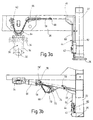
- the in Fig. 1a in the driving position and in Fig. 1b in the raised Pumped concrete pump shown in pump position consists essentially of a two-axle chassis 10, one on a mast bracket 12 near the front axle a vertical axis rotatably mounted concrete placing boom 14, a thick matter pump 16 with material feed container 18 and one of two front and two rear Support legs 20,22 existing support structure.
- the Support legs 20, 22 are each extendable downwards Foot part 24, 26 while lifting the chassis 10 the floor 28 can be supported.
- the wheels 30 of the rear axle 32 are interposed of biased by the action of the axle load Wheel springs 34 suspended from the frame 36 of the chassis 10.
- the wheel springs 34 are in the embodiment shown designed as layered leaf springs. Every bike 30 of the rear axle 32 is also a locking mechanism 38 assigned with which the travel of the respective Wheel spring 34 before lifting into the pumping position according to FIG. 1b locked and thereby the rear axle 32 against the frame 36 can be locked.
- the locking mechanism is coupled to the actuation of the foot part 26 so that he automatically in the reverse direction when extending the foot part and automatically in when retracting the foot section Release direction is actuated.
- the locking mechanism 38 has a for this purpose the action of the foot portion 26 between a release and a locking position relative to a fixed frame Rotation axis 40 pivotable and in the locked position frame-locked, designed as a swivel bolt Locking member 42 and one end of the locking member 42 anchored flexible tension member 44, which in the Locked position of the locking member 42 the travel of the preloaded Wheel spring 34 limited and in the release position of the locking member 42 releasing the travel of the wheel spring Game.
- the embodiment is the tension member 44 as a flexible Traction rope formed from the locking member 42 from two frame-fixed deflection guides 46.48 to a bracket plate 50 performed and anchored there at an anchorage point 52 is.
- the clip plate 50 is rigid with the spring clips 54 connected to which the leaf spring on the wheel axle 32 or on the suspension 56 is held. The In turn, leaf springs are not at their ends spring eyes shown hung on the frame.
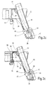
- the exemplary embodiment shown in FIGS. 3a to c differs from the exemplary embodiment according to FIG. 2a to c in that the tension member 44 from a chain section 58 and a rope section 60 composed with the chain section 58 with its free end anchored to a frame-fixed anchoring point 62 and by a curved one arranged on the bracket plate 50 Deflection guide 64 through to a frame-fixed deflection guide 66 is performed.
- a connection point 68 In the area between the frame fixed Deflection guides 66 and 46 is a connection point 68, on which the chain section 58 with the Rope section 60 is connected.
- the tension member 44 of a tension spring 70 bridges, with one end 72 in both cases connected to the tension member 44 via a spring holder 74 while she is with her other end 76 in the case 2b via a further spring holder 78 on Tension member 44 and in the case of Fig. 3b via a spring holder 78 'is attached to the frame 36.
- the tension spring 70 provides for the fact that in the release position of the locking member 42 Tension member 44 to both the locking member 42 and the wheel spring 34 held under a certain bias becomes.
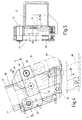
- this is Locking member 42 as on a frame-fixed part of the support leg 22 articulated in the area of the axis of rotation 40, at his the free end 80 opposite the axis of rotation the tension member connected swivel bolt formed the via a rigidly arranged on the extendable foot part 26
- Control member 82 between those drawn in solid lines Release position and the dashed Lines drawn in the locked position against the force the tension spring 70 acting on the tension member 44 is pivotable is.
- the control member 82 has one against one Locking element 42 arranged eccentrically to its axis of rotation Roller cam 84 slidable cam 86 and one connected to the control cam 86, the control element 82 blocking surface 88 arresting in its blocking position.
- the roller cam runs when swiveled into the locked position 84 of the locking member 42 on the locking surface 88 of the Tax body 82 on.
- the blocking surface 88 is parallel to the extension direction indicated by arrow 90 in FIG. 4 of the foot section so that it is for the Locking effect does not matter how far the foot section 26 extended from the fixed part of the support leg 22 is.
- the locking member 42 is 90 ° about its axis of rotation 40 pivoted, with only a relatively short for pivoting Displacement of the foot portion 26 in the direction of Arrow 90 is necessary.
- the invention refers to a mobile work machine, in particular a truck-mounted concrete pump with placing boom and rear wheel side arranged material feed container.
- the mobile Working machine has a chassis 10 that at least four pairs belonging to a wheel axle 32, below Interposition of an axle load preloadable wheel springs 34 suspended from a frame 36 Has wheels 30. Next are in pairs on the side of the frame opposite one another, one of the wheel axles 32, preferably assigned to the rear axle, with an after extendable foot section 26 below while lifting the chassis 10 support legs 22, which can be supported on the bottom, and at least one of the travel of one of the wheel springs 34 optionally releasing or locking locking mechanism provided.
- the locking mechanism is to ensure the axle lock 38 automatically when the foot part 26 extends Locking direction and automatically when retracting the foot part 26 Can be operated in the release direction.
Landscapes
- Engineering & Computer Science (AREA)
- Mechanical Engineering (AREA)
- Architecture (AREA)
- Civil Engineering (AREA)
- Structural Engineering (AREA)
- Vehicle Body Suspensions (AREA)
- Agricultural Machines (AREA)
- Vehicle Cleaning, Maintenance, Repair, Refitting, And Outriggers (AREA)
- Jib Cranes (AREA)
Description
- Fig. 1a und b
- eine Seitenansicht einer Autobetonpumpe in Fahrstellung und in angehobener Pumpstellung;
- Fig. 2a bis c
- eine Seitenansicht, eine Draufsicht und eine Stirnseitenansicht eines Sperrmechanismus für die Achsarretierung;
- Fig. 3a, b und c
- eine Seitenansicht, eine Draufsicht und eine Stirnseitenansicht eines gegenüber Fig. 2a bis c abgewandelten Sperrmechanismus;
- Fig. 4
- einen vergrößerten Ausschnitt aus Fig. 2c und Fig. 3c;
- Fig. 5
- einen Schnitt entlang der Schnittlinie 5-5 der Fig. 4.
Claims (20)
- Fahrbare Arbeitsmaschine mit einem die Arbeitsmaschine (14,16,18) tragenden Fahrgestell (10), das mindestens vier paarweise zu einer Radachse (32) gehörende, unter Zwischenschaltung von durch Einwirkung einer Achslast vorspannbaren Radfedern (34) an einem Rahmen (36) aufgehängte Räder (30) aufweist, mit zwei seitlich am Rahmen (36) einander gegenüberliegenden, einer der Radachse, vorzugsweise der Hinterachse (32) zugeordneten Stützbeinen (20,22), die mit einem vorzugsweise mit hydraulischen Mitteln nach unten ausfahrbarem Fußteil (24,26) unter Anheben des Fahrgestells (10) bodenseitig abstützbar sind, und mit mindestens einem den Federweg einer der Radfedern (34) wahlweise freigebenden oder sperrenden Sperrmechanismus (38), dadurch gekennzeichnet, daß der Sperrmechanismus (38) beim Ausfahren des Fußteils (26) selbsttätig in Sperrrichtung und beim Einfahren des Fußteils (26) selbsttätig in Freigaberichtung betätigbar ist.
- Fahrbare Arbeitsmaschine nach Anspruch 1, dadurch gekennzeichnet, daß der Sperrmechanismus (38) unmittelbar oder mittelbar über das Fußteil (26) oder dessen Betätigungsmechanismus auslösbar oder ansteuerbar ist.
- Fahrbare Arbeitsmaschine nach Anspruch 1 oder 2, dadurch gekennzeichnet, daß der Sperrmechanismus (38) ein unmittelbar oder mittelbar unter der Einwirkung des Fußteils (26) zwischen einer Freigabe- und einer Sperrstellung relativ zu einer rahmenfesten Stelle (Drehachse 40) verschieb- oder verschwenkbares und zumindest in der Sperrstellung rahmenfest arretierbares Sperrorgan (42) aufweist.
- Fahrbare Arbeitsmaschine nach Anspruch 3, dadurch gekennzeichnet, daß der Sperrmechanismus (38) ein an seinem einen Ende am Sperrorgan (42) verankertes, zumindest partiell biegsames Zugglied aufweist, das in der Sperrstellung des Sperrorgans den Federweg der vorgespannten Radfeder (34) begrenzt und in der Freigabestellung des Sperrorgans (42) ein den Federweg der Radfeder freigebendes Spiel aufweist.
- Fahrbare Arbeitsmaschine nach Anspruch 4, dadurch gekennzeichnet, daß das Zugglied (44) vom Sperrorgan (42) aus durch eine radaufhängungsseitig federfeste umlenkführung (64) hindurch zu einer rahmenfesten Verankerungsstelle (62) geführt ist.
- Fahrbare Arbeitsmaschine nach Anspruch 4, dadurch gekennzeichnet, daß das Zugglied (44) vom Sperrorgan aus über eine rahmenfeste Umlenkführung (48) hindurch zu einer radaufhängungsseitigen Verankerungsstelle (52) der Radfeder (34) geführt ist.
- Fahrbare Arbeitsmaschine nach Anspruch 5 oder 6, dadurch gekennzeichnet, daß das Zugglied (44) über mindestens eine weitere rahmenfeste Umlenkführung (46, 66) geführt ist.
- Fahrbare Arbeitsmaschine nach einem der Ansprüche 4 bis 7, dadurch gekennzeichnet, daß die Radfeder (34) als Blattfeder ausgebildet ist, an der die Radaufhängung (56) oder die Radachse (32) mittels Federbriden (54) befestigt ist und daß die federfeste Umlenkführung (64) oder die federfeste Verankerungsstelle (52) des Zugglieds (44) an einer bridenfesten Platte (50) angeordnet ist.
- Fahrbare Arbeitsmaschine nach einem der Ansprüche 4 bis 8, dadurch gekennzeichnet, daß ein biegsamer Abschnitt des Zugglieds (44) von einer spielausgleichenden Zugfeder (70) überbrückt ist.
- Fahrbare Arbeitsmaschine nach Anspruch 9, dadurch gekennzeichnet, daß die Zugfeder (70) an ihrem sperrorganseitigen Ende (72) am Zugglied (44) und an ihrem radseitigen Ende (76) am Rahmen (36) befestigt ist.
- Fahrbare Arbeitsmaschine nach einem der Ansprüche 4 bis 10, dadurch gekennzeichnet, daß das Zugglied (44) zumindest partiell als biegsames Zugseil (60) oder als Kette (58) ausgebildet ist.
- Fahrbare Arbeitsmaschine nach einem der Ansprüche 3 bis 11, dadurch gekennzeichnet, daß das Sperrorgan (42) als am Rahmen (36) oder an einem rahmenfesten Teil des Stützbeins (22) angelenkter, mit dem Zugglied (44) verbundener, über ein am ausfahrbaren Fußteil (26) angeordnetes Steuerorgan (82) zwischen der Freigabestellung und der Sperrstellung verschwenkbarer Schwenkriegel ausgebildet ist.
- Fahrbare Arbeitsmaschine nach Anspruch 12, dadurch gekennzeichnet, daß der Schwenkriegel (42) in Richtung Sperrstellung entgegen der Kraft der am Zugglied (44) angreifenden Zugfeder (70) verschwenkbar ist.
- Fahrbare Arbeitsmaschine nach Anspruch 12 oder 13, dadurch gekennzeichnet, daß das Steuerorgan (82) eine gegen einen am Schwenkriegel (42) exzentrisch zu dessen Drehachse (40) angeordneten Nocken (84) verschiebbare Steuerkurve (86) und eine den Schwenkriegel in seiner Sperrstellung arretierende Sperrfläche (88) aufweist.
- Fahrbare Arbeitsmaschine nach Anspruch 14, dadurch gekennzeichnet, daß die Sperrfläche (88) an die Steuerkurve (86) anschließt und daß der Nocken in der Sperrstellung des Schwenkriegels (42) auf die Sperrfläche (88) aufläuft.
- Fahrbare Arbeitsmaschine nach Anspruch 14 oder 15, dadurch gekennzeichnet, daß die Sperrfläche (88) parallel zur Ausfahrrichtung (90) des Fußteils (26) ausgerichtet ist.
- Fahrbare Arbeitsmaschine nach einem der Ansprüche 12 bis 16, dadurch gekennzeichnet, daß der Schwenkriegel (42) zwischen der Freigabestellung und der Sperrstellung um 90° um seine Drehachse (40) verschwenkbar ist.
- Fahrbare Arbeitsmaschine nach einem der Ansprüche 14 bis 17, dadurch gekennzeichnet, daß der Nocken (84) als Rollnocken ausgebildet ist.
- Fahrbare Arbeitsmaschine nach einem der Ansprüche 1 bis 7 oder 9 bis 18, dadurch gekennzeichnet, daß die Radfeder als Luftfeder ausgebildet ist und daß der Luftdruck in der Luftfeder beim Ausfahren des Fußteils selbsttätig vorzugsweise auf Atmosphärendruck reduziert und beim Einfahren des Fußteils selbsttätig mittels einer Druckluftanlage erhöht wird.
- Fahrbare Arbeitsmaschine nach Anspruch 19, gekennzeichnet durch ein unmittelbar oder mittelbar über das Fußteil oder über den Sperrmechanismus ansteuerbares, die Luftfeder wahlweise mit Druckluft oder mit Atmosphärendruck beaufschlagendes Umsteuerventil.
Applications Claiming Priority (3)
| Application Number | Priority Date | Filing Date | Title |
|---|---|---|---|
| DE19805359 | 1998-02-12 | ||
| DE19805359A DE19805359A1 (de) | 1998-02-12 | 1998-02-12 | Fahrbare Arbeitsmaschine mit Stützbeinen und Achsarretierung |
| PCT/EP1998/008095 WO1999041184A1 (de) | 1998-02-12 | 1998-12-11 | Fahrbare arbeitsmaschine mit stützbeinen und achsarretierung |
Publications (2)
| Publication Number | Publication Date |
|---|---|
| EP1054833A1 EP1054833A1 (de) | 2000-11-29 |
| EP1054833B1 true EP1054833B1 (de) | 2002-10-23 |
Family
ID=7857246
Family Applications (1)
| Application Number | Title | Priority Date | Filing Date |
|---|---|---|---|
| EP98964499A Expired - Lifetime EP1054833B1 (de) | 1998-02-12 | 1998-12-11 | Fahrbare arbeitsmaschine mit stützbeinen und achsarretierung |
Country Status (6)
| Country | Link |
|---|---|
| US (1) | US6293586B1 (de) |
| EP (1) | EP1054833B1 (de) |
| JP (1) | JP2002503607A (de) |
| DE (2) | DE19805359A1 (de) |
| ES (1) | ES2184353T3 (de) |
| WO (1) | WO1999041184A1 (de) |
Families Citing this family (12)
| Publication number | Priority date | Publication date | Assignee | Title |
|---|---|---|---|---|
| DE10112084A1 (de) * | 2001-03-12 | 2002-09-19 | Putzmeister Ag | Fahrbare Dickstoffpumpe mit Stützkonstruktion und luftgefederter Radachse |
| RU2244654C1 (ru) * | 2004-02-02 | 2005-01-20 | Управление механизации № 25 ЗАО Мосстроймеханизации-5 | Полуприцеп-самосвал для грузового автопоезда |
| US20050262741A1 (en) * | 2004-05-29 | 2005-12-01 | Cnh America Llc | Variable-position stabilizer leg |
| KR20150053284A (ko) * | 2013-11-07 | 2015-05-18 | 주식회사 호룡 | 자주식 크레인 |
| CN103663199B (zh) * | 2013-12-13 | 2015-11-18 | 中联重科股份有限公司 | 起重机械 |
| US11052878B2 (en) | 2017-03-29 | 2021-07-06 | Lippert Components, Inc. | Manually-operable hydraulic stabilizing system |
| US10442411B2 (en) * | 2017-03-29 | 2019-10-15 | Lippert Components, Inc. | Manually-operable hydraulic stabilizing system |
| DE102018109224A1 (de) * | 2018-04-18 | 2019-10-24 | Liebherr-Betonpumpen Gmbh | Autobetonpumpe |
| RU187513U1 (ru) * | 2018-09-07 | 2019-03-11 | Публичное акционерное общество "КАМАЗ" | Устройство стопорения грузового автомобиля |
| CN109896443B (zh) * | 2019-04-10 | 2020-04-28 | 吴金奎 | 一种支腿及支腿油缸 |
| CN117881556A (zh) * | 2022-03-18 | 2024-04-12 | 森田控股股份有限公司 | 车辆的轴锁定装置和具备该装置的车辆 |
| DE102024119562A1 (de) * | 2024-07-10 | 2026-01-15 | Putzmeister Engineering Gmbh | Fahrbare Arbeitsmaschine und Verfahren zum Betrieb einer fahrbaren Arbeitsmaschine |
Family Cites Families (19)
| Publication number | Priority date | Publication date | Assignee | Title |
|---|---|---|---|---|
| GB291837A (en) * | 1927-03-02 | 1928-06-05 | Alfred William Farnsworth | Improvements in mobile cranes |
| GB780461A (en) * | 1954-09-17 | 1957-07-31 | Viberti Off Spa | Pneumatic servo-controlled device for locking the suspension of one of the axles of a semi-trailer having more than one axle and/or moving to its operative position the forecarriage supporting the semi-trailer |
| DE2130959A1 (de) * | 1970-07-02 | 1972-01-05 | Kalmar Verkst S Ab | Stuetzbeinvorrichtung |
| GB1358989A (en) * | 1970-09-26 | 1974-07-03 | Steiner Ltd H | Attachments for vehicles |
| FR2215050A5 (de) * | 1973-01-18 | 1974-08-19 | Ppm Sa | |
| US3825280A (en) * | 1973-08-27 | 1974-07-23 | Caterpillar Tractor Co | Adjustable stabilizer support for vehicles |
| SE382778B (sv) * | 1974-02-26 | 1976-02-16 | G M S Berger | Lastfordon forsett med en anordning for fjedrarnas komprimering och dermed berramens senkning |
| DE2848904A1 (de) * | 1978-11-10 | 1980-05-14 | Kruno Znidaric | Fahrzeug zum laden und transportieren von schwergut, insbesondere kraftfahrzeugen |
| SE437636B (sv) * | 1979-12-28 | 1985-03-11 | Soederstroem Berry | Fordon, forsedd med en vrid- eller svengbar hallare for uppberande av ett arbetsredskap |
| DE3122725A1 (de) * | 1981-06-06 | 1982-12-23 | Franz Ing.(Grad.) 8940 Memmingen Fenzl | Tragrahmen fuer die aufnahme einer mobilen arbeitsmaschine zum aufbau auf ein fahrgestell |
| US4466637A (en) * | 1981-09-22 | 1984-08-21 | Nelson Carl A | Power drive mechanism for trailer landing gear |
| US4583760A (en) * | 1984-09-04 | 1986-04-22 | Clark Equipment Company | Vehicle stabilizer attachment and method |
| DE3934499C2 (de) * | 1989-10-16 | 1998-01-15 | Georg Deuringer | Fahrzeug, insbesondere Kran- oder Transportfahrzeug für Fertiggaragen |
| DE4231441B4 (de) * | 1992-09-19 | 2005-11-03 | Iveco Magirus Ag | Verfahren zur Sicherung eines Krans oder Hubrettungsfahrzeugs vor einem Kippen sowie Kippsicherung zur Durchführung des Verfahrens |
| DE9316007U1 (de) * | 1992-11-04 | 1994-01-05 | Franz Plasser Bahnbaumaschinen-Industriegesellschaft M.B.H., Wien | Verladewagen zum Speichern von Schüttgut |
| US5387071A (en) * | 1993-06-29 | 1995-02-07 | Pinkston; Donald L. | Rotatable recovery vehicle |
| US5401046A (en) * | 1994-02-01 | 1995-03-28 | Charlie E. Schwartz | Trailer and lifting mechanism |
| DE19503895A1 (de) * | 1995-02-07 | 1996-08-08 | Putzmeister Maschf | Betonpumpe mit Verteilermast |
| DE19531697A1 (de) * | 1995-08-29 | 1997-03-06 | Putzmeister Maschf | Fahrbare Arbeitsmaschine mit seitlich ausschwenkbaren Stützauslegern |
-
1998
- 1998-02-12 DE DE19805359A patent/DE19805359A1/de not_active Withdrawn
- 1998-12-11 DE DE59806080T patent/DE59806080D1/de not_active Expired - Fee Related
- 1998-12-11 WO PCT/EP1998/008095 patent/WO1999041184A1/de not_active Ceased
- 1998-12-11 ES ES98964499T patent/ES2184353T3/es not_active Expired - Lifetime
- 1998-12-11 EP EP98964499A patent/EP1054833B1/de not_active Expired - Lifetime
- 1998-12-11 JP JP2000531389A patent/JP2002503607A/ja active Pending
- 1998-12-11 US US09/446,528 patent/US6293586B1/en not_active Expired - Fee Related
Also Published As
| Publication number | Publication date |
|---|---|
| EP1054833A1 (de) | 2000-11-29 |
| DE19805359A1 (de) | 1999-08-19 |
| ES2184353T3 (es) | 2003-04-01 |
| JP2002503607A (ja) | 2002-02-05 |
| WO1999041184A1 (de) | 1999-08-19 |
| US6293586B1 (en) | 2001-09-25 |
| DE59806080D1 (de) | 2002-11-28 |
Similar Documents
| Publication | Publication Date | Title |
|---|---|---|
| EP1135322B1 (de) | Kran, insbesondere fahrzeugkran | |
| EP0354167B1 (de) | Kran, insbesondere Grosskran | |
| EP1054833B1 (de) | Fahrbare arbeitsmaschine mit stützbeinen und achsarretierung | |
| CH427176A (de) | Automobilkran mit teleskopartig ausfahr- bzw. einziehbarem Ausleger | |
| DE3838975C2 (de) | ||
| AT523474B1 (de) | Auslegersystem für einen Fahrzeugkran mit Abspannvorrichtung sowie Verfahren zum Aufrüsten und Abrüsten einer Abspannvorrichtung eines Fahrzeugkrans | |
| DE2601565A1 (de) | Vorrichtung zur steuerung und arretierung von stuetzauslegern eines fahrzeuges | |
| DE1531146B2 (de) | Hydraulischer antrieb fuer einen kranausleger mit teleskopartig verschiebbaren auslegerstuecken | |
| DE102021111922B3 (de) | Abspannsystem und -verfahren für einen Mobilkran-Teleskopausleger | |
| DE102013008434B4 (de) | Autobetonpumpe mit Unterfahrschutz | |
| DE3611593C2 (de) | ||
| DE2450003C2 (de) | Fahrzeugkran mit Kabine mit verschiedenen Stellungen | |
| DE102019122071B3 (de) | Teleskopausleger mit ausklappbarem Mast | |
| DE2205025C2 (de) | Kran auf einem Transportfahrzeug | |
| AT304814B (de) | Fahrbare Maschine zum Heben von Lasten, insbesondere von Kraftfahrzeugen | |
| DE2635387C2 (de) | Kran | |
| DE2628917B2 (de) | ||
| DE8129801U1 (de) | Bergungsfahrzeug | |
| DE3810070A1 (de) | Von einem fahrzeug getragener hoehenfoerderer | |
| DE2947723C2 (de) | Transportfahrzeug mit Hebevorrichtung für Fertiggaragen oder dergleichen | |
| DE3326573A1 (de) | Bergungskran fuer abschleppfahrzeuge | |
| EP4053066A2 (de) | Vorrichtung und verfahren zur montage / demontage eines mobilkranauslegers | |
| DE1655690A1 (de) | Hub- und Abschleppvorrichtung fuer Fahrzeuge | |
| CH499457A (de) | Auf einem Fahrgestell montierter Auslegerkran | |
| EP0927698A1 (de) | Auf Rädern fahrbares querbewegliches Arbeitsgerät |
Legal Events
| Date | Code | Title | Description |
|---|---|---|---|
| PUAI | Public reference made under article 153(3) epc to a published international application that has entered the european phase |
Free format text: ORIGINAL CODE: 0009012 |
|
| 17P | Request for examination filed |
Effective date: 19991110 |
|
| AK | Designated contracting states |
Kind code of ref document: A1 Designated state(s): DE ES FR GB IT |
|
| GRAG | Despatch of communication of intention to grant |
Free format text: ORIGINAL CODE: EPIDOS AGRA |
|
| 17Q | First examination report despatched |
Effective date: 20020125 |
|
| GRAG | Despatch of communication of intention to grant |
Free format text: ORIGINAL CODE: EPIDOS AGRA |
|
| GRAG | Despatch of communication of intention to grant |
Free format text: ORIGINAL CODE: EPIDOS AGRA |
|
| GRAH | Despatch of communication of intention to grant a patent |
Free format text: ORIGINAL CODE: EPIDOS IGRA |
|
| GRAH | Despatch of communication of intention to grant a patent |
Free format text: ORIGINAL CODE: EPIDOS IGRA |
|
| GRAA | (expected) grant |
Free format text: ORIGINAL CODE: 0009210 |
|
| AK | Designated contracting states |
Kind code of ref document: B1 Designated state(s): DE ES FR GB IT |
|
| REG | Reference to a national code |
Ref country code: GB Ref legal event code: FG4D Free format text: NOT ENGLISH |
|
| REF | Corresponds to: |
Ref document number: 59806080 Country of ref document: DE Date of ref document: 20021128 |
|
| GBT | Gb: translation of ep patent filed (gb section 77(6)(a)/1977) |
Effective date: 20021126 |
|
| REG | Reference to a national code |
Ref country code: ES Ref legal event code: FG2A Ref document number: 2184353 Country of ref document: ES Kind code of ref document: T3 |
|
| ET | Fr: translation filed | ||
| PLBE | No opposition filed within time limit |
Free format text: ORIGINAL CODE: 0009261 |
|
| STAA | Information on the status of an ep patent application or granted ep patent |
Free format text: STATUS: NO OPPOSITION FILED WITHIN TIME LIMIT |
|
| 26N | No opposition filed |
Effective date: 20030724 |
|
| PGFP | Annual fee paid to national office [announced via postgrant information from national office to epo] |
Ref country code: ES Payment date: 20071214 Year of fee payment: 10 |
|
| PGFP | Annual fee paid to national office [announced via postgrant information from national office to epo] |
Ref country code: IT Payment date: 20071220 Year of fee payment: 10 |
|
| PGFP | Annual fee paid to national office [announced via postgrant information from national office to epo] |
Ref country code: GB Payment date: 20071127 Year of fee payment: 10 Ref country code: FR Payment date: 20071114 Year of fee payment: 10 |
|
| PGFP | Annual fee paid to national office [announced via postgrant information from national office to epo] |
Ref country code: DE Payment date: 20071222 Year of fee payment: 10 |
|
| REG | Reference to a national code |
Ref country code: FR Ref legal event code: CJ Ref country code: FR Ref legal event code: CD |
|
| GBPC | Gb: european patent ceased through non-payment of renewal fee |
Effective date: 20081211 |
|
| REG | Reference to a national code |
Ref country code: FR Ref legal event code: ST Effective date: 20090831 |
|
| PG25 | Lapsed in a contracting state [announced via postgrant information from national office to epo] |
Ref country code: DE Free format text: LAPSE BECAUSE OF NON-PAYMENT OF DUE FEES Effective date: 20090701 |
|
| PG25 | Lapsed in a contracting state [announced via postgrant information from national office to epo] |
Ref country code: GB Free format text: LAPSE BECAUSE OF NON-PAYMENT OF DUE FEES Effective date: 20081211 |
|
| REG | Reference to a national code |
Ref country code: ES Ref legal event code: FD2A Effective date: 20081212 |
|
| PG25 | Lapsed in a contracting state [announced via postgrant information from national office to epo] |
Ref country code: FR Free format text: LAPSE BECAUSE OF NON-PAYMENT OF DUE FEES Effective date: 20081231 Ref country code: ES Free format text: LAPSE BECAUSE OF NON-PAYMENT OF DUE FEES Effective date: 20081212 |
|
| PG25 | Lapsed in a contracting state [announced via postgrant information from national office to epo] |
Ref country code: IT Free format text: LAPSE BECAUSE OF NON-PAYMENT OF DUE FEES Effective date: 20081211 |