EP1055048B1 - Vorrichtung zum abgeben von bohrlochrohren ins bohrloch - Google Patents
Vorrichtung zum abgeben von bohrlochrohren ins bohrloch Download PDFInfo
- Publication number
- EP1055048B1 EP1055048B1 EP99905011A EP99905011A EP1055048B1 EP 1055048 B1 EP1055048 B1 EP 1055048B1 EP 99905011 A EP99905011 A EP 99905011A EP 99905011 A EP99905011 A EP 99905011A EP 1055048 B1 EP1055048 B1 EP 1055048B1
- Authority
- EP
- European Patent Office
- Prior art keywords
- tray
- tubular
- arm
- ramp
- pipe
- Prior art date
- Legal status (The legal status is an assumption and is not a legal conclusion. Google has not performed a legal analysis and makes no representation as to the accuracy of the status listed.)
- Expired - Lifetime
Links
- 238000000034 method Methods 0.000 description 3
- 238000010276 construction Methods 0.000 description 1
- 238000005553 drilling Methods 0.000 description 1
- 230000000694 effects Effects 0.000 description 1
- 231100001261 hazardous Toxicity 0.000 description 1
- 230000000284 resting effect Effects 0.000 description 1
Images


Classifications
-
- E—FIXED CONSTRUCTIONS
- E21—EARTH OR ROCK DRILLING; MINING
- E21B—EARTH OR ROCK DRILLING; OBTAINING OIL, GAS, WATER, SOLUBLE OR MELTABLE MATERIALS OR A SLURRY OF MINERALS FROM WELLS
- E21B19/00—Handling rods, casings, tubes or the like outside the borehole, e.g. in the derrick; Apparatus for feeding the rods or cables
- E21B19/20—Combined feeding from rack and connecting, e.g. automatically
-
- E—FIXED CONSTRUCTIONS
- E21—EARTH OR ROCK DRILLING; MINING
- E21B—EARTH OR ROCK DRILLING; OBTAINING OIL, GAS, WATER, SOLUBLE OR MELTABLE MATERIALS OR A SLURRY OF MINERALS FROM WELLS
- E21B19/00—Handling rods, casings, tubes or the like outside the borehole, e.g. in the derrick; Apparatus for feeding the rods or cables
- E21B19/14—Racks, ramps, troughs or bins, for holding the lengths of rod singly or connected; Handling between storage place and borehole
- E21B19/15—Racking of rods in horizontal position; Handling between horizontal and vertical position
- E21B19/155—Handling between horizontal and vertical position
Definitions
- This invention relates to an apparatus for delivering a tubular to a well centre.
- each tubular is transferred to the V-slot adjacent the rig floor by a conveyor.
- the tubular is then lifted by an elevator and swung into position over the well centre ready for attachment to a string of tubulars extending down the well.
- US3,795,326 describes an apparatus for transferring a drill pipe from a horizontal to a vertical position over a well. Movement of the pipe is controlled during transfer by a pipe carriage riding on a fixed track.
- An aim of at least preferred embodiments of the present invention is to reduce this problem.
- an apparatus for delivering a tubular to a well centre comprises means which, in use, inhibit swinging motion of the tubular whilst it is suspended from an elevator, said means comprising an arm which is pivotable between a first position and a second position, characterised by a swivel drive coupled to said arm and arranged in use to rotate the arm so as to bring the longitudinal axis of the tubular from an inclined position with respect to the longitudinal axis of the well to a position which is substantially in alignment with the axis of the well.
- said arm is provided with a stub axle which is provided with rollers for supporting said tubular.
- the apparatus further comprises a ramp which can be placed against a rig floor, and a tray which can support a tubular and be moved along said ramp.
- the ramp may define an angle with the horizontal of between 30 degrees and 70 degrees, but it is normally intended to be used at angles of from 110 to 60 degrees.
- said arm is mounted on said ramp.
- said arm is mounted on said tray.
- the arm may be mounted on the derrick.
- said swivel drive comprises an hydraulic motor.
- the apparatus comprises a ramp which can be placed against a rig floor, and a tray for carrying said tubular
- the apparatus preferably comprises means which, in use, enables said tray to ascend or descend said ramp.
- said ramp further comprises a rack.
- said means is a pinion mounted on said tray and engageable with said rack.
- the means by which the tray moves along the ramp may be of any suitable means, but is preferably a rack and pinion.
- said means comprises two pinions, one mounted adjacent each end of said tray.
- said tray further comprises a support wheel.
- said tray further comprises a pipe sledge mounted for longitudinal movement therein.
- said tray further comprises a pipe pusher mounted such that, in use, said pipe pusher moves said tubular longitudinally within said tray.
- said pipe pusher comprises a piston and cylinder.
- FIG. 1 there is shown an apparatus which is generally identified by reference numeral 1.
- the apparatus 1 comprises a ramp 3 which extends upwardly to a rig floor 2 and a pipe tray 4.
- the ramp 3 extends between the pipe tray 4 and a V-slot (not shown) in a derrick 5.
- the derrick 5 is provided with an elevator 6 which is supported from a top drive slidably mounted on a track 7.
- a tubular 8 is shown within the derrick 5 having been screwed or otherwise attached to a string of tubulars (not shown) which extend down a wellbore (not shown) at the well centre.
- a tubular 9 is shown resting on the pipe tray 4 and is to be attached to the tubular 8 in the process of increasing the length of the string of tubulars within the wellbore.
- the ramp 3 further comprises a rack 10 which extends from the lower end of ramp 3 to the upper end of ramp 3.
- the pipe tray 4 further comprises two pinions 11, 12 which can be rotated by respective hydraulic motors (not shown) so that, in use, the pipe tray 4 can move either up or down the rack 10.
- the pinion 11 is located at one end of the pipe tray 4 whilst the pinion 12 is located at the opposite end of pipe tray 4.
- a stabbing arm 13 is pivotally mounted at the end of pipe tray 4 and may be rotated by means of a swivel drive 14.
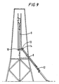
- Swivel drive 14 can be actuated by a hydraulic motor (not shown) to move the stabbing arm 13 between a first position shown in Fig. 2 and a second position shown in Fig. 9 as more fully described hereafter.
- the stabbing arm 13 is provided with a stub axle which carries rollers 19 to facilitate longitudinal movement of the tubular 9.
- a pipe sledge 15 resides within and at the rear end of the pipe tray 4.
- the pipe sledge 15 has rollers 20 mounted at each end so that in use the pipe sledge 15 can move along the longitudinal axis of the pipe tray 4.
- a pipe pusher 16 which comprises a piston and cylinder is located substantially in abutment with the pipe sledge 15.
- the pipe pusher 16 can be hydraulically activated so that the piston of the pipe pusher 16 will exert a force on the pipe sledge 15 to move the tubular 9 longitudinally within the pipe tray 4.
- Elastomeric sliding plates 18 are provided along the length of pipe tray 4 and allow the tubular 9 to rest therein. In use, the elastomeric sliding plates 18 are movable within the pipe tray 4 to help support the tubular 9.
- a support wheel 17 is located at the rear end of the pipe tray 4 which, in use, allows movement of the pipe tray 4 towards the V-slot in the derrick 5.
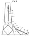
- FIGS 3 to 9 show the apparatus in use.
- the tubular 9 Prior to using the apparatus 1 the tubular 9 is rolled onto the pipe tray 4 from a pipe deck (not shown).
- the pinion 11 is rotated.
- the teeth of the pinion 11 engage the rack 10 moving the pipe tray 4 toward the V-slot (not shown) in the derrick 5, as shown in Fig. 3.
- the pinion 12 is rotated as it nears the ramp 3 so that upon engagement with the ramp 3 the pipe tray 4 continues to move toward the V-slot in the derrick 5.
- the tubular 9 is pushed out of the pipe tray 4 by extending the piston in the pipe pusher 16.
- the tubular 9 is pushed to a position where the elevator 6 can be easily attached to the tubular 9 as shown in Fig. 6.
- Fig. 7 shows the elevator 6 having lifted the tubular 9 to a position where the lower end of tubular 9 is near the rollers 19 of the stabbing lever 13 and the upper end is substantially above the well centre.
- Swivel drive 14 is now engaged to rotate the stabbing arm 13 clockwise between the first position, shown in Fig. 7, and the second position, shown in Fig. 9.
- Movement of the stabbing arm 13 brings the longitudinal axis of the tubular 9 from an inclined position with respect to the longitudinal axis of the borehole (not shown), to a position which is substantially in alignment with the axis of the borehole (Fig. 9) (well centre).
- the rollers 19 allow substantially vertical movement of the tubular 9.
Landscapes
- Engineering & Computer Science (AREA)
- Geology (AREA)
- Life Sciences & Earth Sciences (AREA)
- Mining & Mineral Resources (AREA)
- Physics & Mathematics (AREA)
- Environmental & Geological Engineering (AREA)
- Fluid Mechanics (AREA)
- Mechanical Engineering (AREA)
- General Life Sciences & Earth Sciences (AREA)
- Geochemistry & Mineralogy (AREA)
- Earth Drilling (AREA)
- Piles And Underground Anchors (AREA)
- Filling Or Discharging Of Gas Storage Vessels (AREA)
- Treatment Of Fiber Materials (AREA)
Claims (14)
- Vorrichtung (1) zum Abgeben eines Bohrlochrohres (9) in ein Bohrlochzentrum, wobei die Vorrichtung eine Einrichtung (13, 14) aufweist, die bei Benutzung eine Schwingbewegung des Bohrlochrohres (9) behindert, während es von einem Förderwerk herabhängt, wobei die Einrichtung einen Arm (13) aufweist, der zwischen einer ersten Position und einer zweiten Position drehbar ist, gekennzeichnet durch einen Rotationskopfantrieb (14), der mit dem Arm (13) gekoppelt und so angeordnet ist, daß er bei Benutzung den Arm so dreht, daß die Längsachse des Bohrlochrohres aus einer geneigten Position mit Bezugnahme auf die Längsachse des Bohrloches in eine Position gebracht wird, die im wesentlichen mit der Achse des Bohrloches in Ausrichtung ist.
- Vorrichtung (1) nach Anspruch 1, bei der der Arm (13) mit einem Achsschenkel versehen ist, der mit Rollen (19) für das Tragen des Bohrlochrohres (9) versehen ist.
- Vorrichtung (1) nach einem der vorhergehenden Ansprüche, bei der der Arm (13) um seine Achse drehbar ist, um das Bohrlochrohr (9) davon freizugeben.
- Vorrichtung (1) nach einem der vorhergehenden Ansprüche, bei der der Rotationskopfantrieb (14) einen Hydraulikmotor umfaßt, um die Einrichtung zu drehen.
- Vorrichtung (1) nach vorhergehenden Ansprüchen, die außerdem aufweist: eine Abschrägung (3), die gegen einen Bohrgerüstboden (2) angeordnet werden kann; und eine Mulde (4), die ein Bohrlochrohr (9) tragen und längs der Abschrägung (3) bewegt werden kann.
- Vorrichtung (1) nach Anspruch 5, bei der der Arm (13) an der Abschrägung (3) montiert ist.
- Vorrichtung (1) nach Anspruch 5, bei der der Arm (13) an der Mulde (4) montiert ist.
- Vorrichtung (1) nach einem der Ansprüche 5 bis 7, bei der die Abschrägung (3) außerdem ein Gestell (10) aufweist.
- Vorrichtung (1) nach Anspruch 8, und die ein Ritzel (11) aufweist, das an der Mulde (4) montiert ist und mit dem Gestell (10) in Eingriff kommen kann, damit sich die Mulde (4) auf der Abschrägung (3) aufwärts oder abwärts bewegen kann..
- Vorrichtung (1) nach Anspruch 8, und die außerdem zwei Ritzel (11, 12) aufweist, wobei eines angrenzend an jedes Ende der Mulde (4) montiert ist, damit sich die Mulde (4) auf der Abschrägung (3) aufwärts oder abwärts bewegen kann.
- Vorrichtung (1) nach einem der Ansprüche 5 bis 10, bei der die Mulde (4) außerdem ein Stützrad (17) aufweist.
- Vorrichtung nach einem der Ansprüche 5 bis 11, bei der die Mulde (4) außerdem einen Rohrschlitten (15) aufweist, der für eine Längsbewegung darin montiert ist.
- Vorrichtung (1) nach einem der Ansprüche 5 bis 12, bei der die Mulde (4) außerdem eine Rohrausstoßvorrichtung (16) aufweist, die so montiert ist, daß die Rohrausstoßvorrichtung (16) bei Benutzung das Bohrlochrohr (9) in Längsrichtung innerhalb der Mulde (4) bewegt.
- Vorrichtung (1) nach Anspruch 13, bei der die Rohrausstoßvorrichtung einen Kolben und Zylinder aufweist.
Applications Claiming Priority (3)
| Application Number | Priority Date | Filing Date | Title |
|---|---|---|---|
| GB9803116 | 1998-02-14 | ||
| GBGB9803116.4A GB9803116D0 (en) | 1998-02-14 | 1998-02-14 | Apparatus for delivering a tubular to a wellbore |
| PCT/GB1999/000422 WO1999041485A1 (en) | 1998-02-14 | 1999-02-11 | Apparatus for delivering a tubular to a wellbore |
Publications (2)
| Publication Number | Publication Date |
|---|---|
| EP1055048A1 EP1055048A1 (de) | 2000-11-29 |
| EP1055048B1 true EP1055048B1 (de) | 2003-09-24 |
Family
ID=10826967
Family Applications (1)
| Application Number | Title | Priority Date | Filing Date |
|---|---|---|---|
| EP99905011A Expired - Lifetime EP1055048B1 (de) | 1998-02-14 | 1999-02-11 | Vorrichtung zum abgeben von bohrlochrohren ins bohrloch |
Country Status (7)
| Country | Link |
|---|---|
| US (2) | US6695559B1 (de) |
| EP (1) | EP1055048B1 (de) |
| AU (1) | AU2532199A (de) |
| CA (1) | CA2328184C (de) |
| DE (1) | DE69911583T2 (de) |
| GB (1) | GB9803116D0 (de) |
| WO (1) | WO1999041485A1 (de) |
Families Citing this family (78)
| Publication number | Priority date | Publication date | Assignee | Title |
|---|---|---|---|---|
| US7036610B1 (en) | 1994-10-14 | 2006-05-02 | Weatherford / Lamb, Inc. | Apparatus and method for completing oil and gas wells |
| US7108084B2 (en) | 1994-10-14 | 2006-09-19 | Weatherford/Lamb, Inc. | Methods and apparatus for cementing drill strings in place for one pass drilling and completion of oil and gas wells |
| US7100710B2 (en) | 1994-10-14 | 2006-09-05 | Weatherford/Lamb, Inc. | Methods and apparatus for cementing drill strings in place for one pass drilling and completion of oil and gas wells |
| US7147068B2 (en) | 1994-10-14 | 2006-12-12 | Weatherford / Lamb, Inc. | Methods and apparatus for cementing drill strings in place for one pass drilling and completion of oil and gas wells |
| US7228901B2 (en) | 1994-10-14 | 2007-06-12 | Weatherford/Lamb, Inc. | Method and apparatus for cementing drill strings in place for one pass drilling and completion of oil and gas wells |
| US6868906B1 (en) | 1994-10-14 | 2005-03-22 | Weatherford/Lamb, Inc. | Closed-loop conveyance systems for well servicing |
| US7013997B2 (en) | 1994-10-14 | 2006-03-21 | Weatherford/Lamb, Inc. | Methods and apparatus for cementing drill strings in place for one pass drilling and completion of oil and gas wells |
| US7040420B2 (en) | 1994-10-14 | 2006-05-09 | Weatherford/Lamb, Inc. | Methods and apparatus for cementing drill strings in place for one pass drilling and completion of oil and gas wells |
| US7140445B2 (en) | 1997-09-02 | 2006-11-28 | Weatherford/Lamb, Inc. | Method and apparatus for drilling with casing |
| US7509722B2 (en) | 1997-09-02 | 2009-03-31 | Weatherford/Lamb, Inc. | Positioning and spinning device |
| US6742596B2 (en) | 2001-05-17 | 2004-06-01 | Weatherford/Lamb, Inc. | Apparatus and methods for tubular makeup interlock |
| US6536520B1 (en) | 2000-04-17 | 2003-03-25 | Weatherford/Lamb, Inc. | Top drive casing system |
| GB9803116D0 (en) * | 1998-02-14 | 1998-04-08 | Weatherford Lamb | Apparatus for delivering a tubular to a wellbore |
| GB9815809D0 (en) | 1998-07-22 | 1998-09-16 | Appleton Robert P | Casing running tool |
| GB2340858A (en) | 1998-08-24 | 2000-03-01 | Weatherford Lamb | Methods and apparatus for facilitating the connection of tubulars using a top drive |
| GB2340857A (en) | 1998-08-24 | 2000-03-01 | Weatherford Lamb | An apparatus for facilitating the connection of tubulars and alignment with a top drive |
| GB2340859A (en) | 1998-08-24 | 2000-03-01 | Weatherford Lamb | Method and apparatus for facilitating the connection of tubulars using a top drive |
| US7188687B2 (en) | 1998-12-22 | 2007-03-13 | Weatherford/Lamb, Inc. | Downhole filter |
| WO2000037766A2 (en) | 1998-12-22 | 2000-06-29 | Weatherford/Lamb, Inc. | Procedures and equipment for profiling and jointing of pipes |
| GB2347441B (en) | 1998-12-24 | 2003-03-05 | Weatherford Lamb | Apparatus and method for facilitating the connection of tubulars using a top drive |
| GB2345074A (en) | 1998-12-24 | 2000-06-28 | Weatherford Lamb | Floating joint to facilitate the connection of tubulars using a top drive |
| US7311148B2 (en) | 1999-02-25 | 2007-12-25 | Weatherford/Lamb, Inc. | Methods and apparatus for wellbore construction and completion |
| US6896075B2 (en) | 2002-10-11 | 2005-05-24 | Weatherford/Lamb, Inc. | Apparatus and methods for drilling with casing |
| US6857487B2 (en) | 2002-12-30 | 2005-02-22 | Weatherford/Lamb, Inc. | Drilling with concentric strings of casing |
| GB2348844A (en) | 1999-04-13 | 2000-10-18 | Weatherford Lamb | Apparatus and method for aligning tubulars |
| US7216727B2 (en) | 1999-12-22 | 2007-05-15 | Weatherford/Lamb, Inc. | Drilling bit for drilling while running casing |
| US7334650B2 (en) | 2000-04-13 | 2008-02-26 | Weatherford/Lamb, Inc. | Apparatus and methods for drilling a wellbore using casing |
| US7325610B2 (en) * | 2000-04-17 | 2008-02-05 | Weatherford/Lamb, Inc. | Methods and apparatus for handling and drilling with tubulars or casing |
| GB0010378D0 (en) | 2000-04-28 | 2000-06-14 | Bbl Downhole Tools Ltd | Expandable apparatus for drift and reaming a borehole |
| GB2365463B (en) | 2000-08-01 | 2005-02-16 | Renovus Ltd | Drilling method |
| CA2419885A1 (en) * | 2002-02-25 | 2003-08-25 | Charlie W. Sawyer | Tubular handling apparatus and method |
| GB0206227D0 (en) | 2002-03-16 | 2002-05-01 | Weatherford Lamb | Bore-lining and drilling |
| US6994176B2 (en) | 2002-07-29 | 2006-02-07 | Weatherford/Lamb, Inc. | Adjustable rotating guides for spider or elevator |
| US6899186B2 (en) | 2002-12-13 | 2005-05-31 | Weatherford/Lamb, Inc. | Apparatus and method of drilling with casing |
| US7431550B2 (en) * | 2002-10-04 | 2008-10-07 | Technologies Alliance | Pipe handling apparatus for pick-up and lay-down machine |
| US7303022B2 (en) | 2002-10-11 | 2007-12-04 | Weatherford/Lamb, Inc. | Wired casing |
| US7128154B2 (en) | 2003-01-30 | 2006-10-31 | Weatherford/Lamb, Inc. | Single-direction cementing plug |
| USRE42877E1 (en) | 2003-02-07 | 2011-11-01 | Weatherford/Lamb, Inc. | Methods and apparatus for wellbore construction and completion |
| WO2004076804A1 (en) | 2003-02-27 | 2004-09-10 | Weatherford/Lamb Inc. | Drill shoe |
| US7503397B2 (en) | 2004-07-30 | 2009-03-17 | Weatherford/Lamb, Inc. | Apparatus and methods of setting and retrieving casing with drilling latch and bottom hole assembly |
| US7360594B2 (en) | 2003-03-05 | 2008-04-22 | Weatherford/Lamb, Inc. | Drilling with casing latch |
| CA2517895C (en) | 2003-03-05 | 2009-12-01 | Weatherford/Lamb, Inc. | Casing running and drilling system |
| CA2517883C (en) | 2003-03-05 | 2010-01-12 | Weatherford/Lamb, Inc. | Full bore lined wellbores |
| US7874352B2 (en) | 2003-03-05 | 2011-01-25 | Weatherford/Lamb, Inc. | Apparatus for gripping a tubular on a drilling rig |
| WO2004090279A1 (en) | 2003-04-04 | 2004-10-21 | Weatherford/Lamb, Inc. | Method and apparatus for handling wellbore tubulars |
| US7264067B2 (en) | 2003-10-03 | 2007-09-04 | Weatherford/Lamb, Inc. | Method of drilling and completing multiple wellbores inside a single caisson |
| US20050135902A1 (en) * | 2003-12-18 | 2005-06-23 | Spisak Timothy M. | Pipe transfer apparatus |
| US6994505B2 (en) * | 2004-01-09 | 2006-02-07 | Frank's International | Pick-up and lay-down system and method |
| US7284617B2 (en) | 2004-05-20 | 2007-10-23 | Weatherford/Lamb, Inc. | Casing running head |
| US7552775B2 (en) * | 2005-05-02 | 2009-06-30 | Weatherford/Lamb, Inc. | Tailing in and stabbing device and method |
| US7832974B2 (en) * | 2005-06-01 | 2010-11-16 | Canrig Drilling Technology Ltd. | Pipe-handling apparatus |
| CA2551884C (en) * | 2005-07-19 | 2009-12-15 | National-Oilwell, L.P. | Single joint drilling system with inclined pipe handling system |
| CA2586317C (en) * | 2006-04-27 | 2012-04-03 | Weatherford/Lamb, Inc. | Torque sub for use with top drive |
| US7882902B2 (en) * | 2006-11-17 | 2011-02-08 | Weatherford/Lamb, Inc. | Top drive interlock |
| US7802636B2 (en) | 2007-02-23 | 2010-09-28 | Atwood Oceanics, Inc. | Simultaneous tubular handling system and method |
| US20090053013A1 (en) * | 2007-08-20 | 2009-02-26 | Maltby Scott R | Portable drill pipe handling apparatus for use with oil and gas well drilling rigs |
| US7568533B2 (en) * | 2007-11-16 | 2009-08-04 | Rodger Lawrence Felt | Pipehandler |
| US8033779B2 (en) | 2008-01-31 | 2011-10-11 | Canrig Drilling Technology Ltd. | Pipe handling apparatus and methods |
| US8016536B2 (en) * | 2008-04-04 | 2011-09-13 | Canrig Drilling Technology Ltd. | Pipe-handling apparatus and methods |
| CA2713676C (en) * | 2009-09-22 | 2015-04-14 | Nathan Crossley | Apparatus and method for handling tubulars |
| US8215888B2 (en) | 2009-10-16 | 2012-07-10 | Friede Goldman United, Ltd. | Cartridge tubular handling system |
| US8424616B2 (en) | 2010-02-23 | 2013-04-23 | National Oilwell Varco, L.P. | Track guiding system |
| US9157286B2 (en) * | 2011-10-11 | 2015-10-13 | Warrier Rig Ltd | Portable pipe handling system |
| US9115550B2 (en) * | 2012-04-14 | 2015-08-25 | Kasia L. Robnett | Robotic disassembly method at a well site |
| SE536564C2 (sv) | 2012-06-28 | 2014-02-25 | Atlas Copco Rocktech Ab | Anordning och förfarande för hantering av borrsträngskomponenter samt bergborrigg |
| SE536563C2 (sv) * | 2012-06-28 | 2014-02-25 | Atlas Copco Rocktech Ab | Anordning och förfarande för hantering av borrsträngskomponenter samt bergborrigg |
| US9388647B2 (en) | 2012-08-15 | 2016-07-12 | Liberty Holdings, LLC | Pipe handler |
| CA2841517C (en) * | 2014-02-05 | 2021-06-15 | Real C. Garant | Dock installation apparatus and method |
| US10012038B2 (en) | 2014-07-15 | 2018-07-03 | Warrior Rig Technologies Limited | Pipe handling apparatus and methods |
| US10012039B2 (en) * | 2015-04-15 | 2018-07-03 | Forum Us, Inc. | Tubular handling system |
| US10513895B2 (en) | 2016-04-30 | 2019-12-24 | Cameron International Corporation | Pipe transport system and method |
| WO2017192531A1 (en) * | 2016-05-02 | 2017-11-09 | Cameron International Corporation | Catwalk and crane system |
| US10920504B1 (en) | 2018-07-20 | 2021-02-16 | Hawker Equipment Solutions, LLC. | Pipe grabber |
| US10626687B1 (en) | 2018-09-14 | 2020-04-21 | Hawker Equipment Solutions, LLC. | Wedge system to extend and elevate a pipe handler |
| US11454069B2 (en) | 2020-04-21 | 2022-09-27 | Schlumberger Technology Corporation | System and method for handling a tubular member |
| CN112211574B (zh) * | 2020-09-28 | 2023-08-29 | 中油国家油气钻井装备工程技术研究中心有限公司 | 一种无顶驱工况下推扶式管柱处理设备的排钻柱方法 |
| PL4248051T3 (pl) * | 2020-11-20 | 2025-12-22 | Evolution Drill Rigs Pty Ltd | System obsługi żerdzi do wiertnic |
| WO2022191967A1 (en) * | 2021-03-12 | 2022-09-15 | Schlumberger Technology Corporation | System and method for handling tools at a wellsite |
Family Cites Families (21)
| Publication number | Priority date | Publication date | Assignee | Title |
|---|---|---|---|---|
| US2959371A (en) * | 1956-08-13 | 1960-11-08 | Geolograph Co | Retrieving mechanism |
| US3613905A (en) * | 1970-04-06 | 1971-10-19 | Moore Corp Lee C | Method and apparatus for handling drill pipe |
| US3655071A (en) * | 1970-05-27 | 1972-04-11 | Byron Jackson Inc | Horizontal pipe racking and handling apparatus |
| US3780883A (en) * | 1971-03-18 | 1973-12-25 | Brown Oil Tools | Pipe handling system for use in well drilling |
| US3795326A (en) * | 1972-05-22 | 1974-03-05 | Armco Steel Corp | Apparatus for handling drill pipe |
| SE388453B (sv) * | 1973-05-08 | 1976-10-04 | Atlas Copco Ab | Anordning for forflyttning av stenger fran ett magasinerat lege till centrumaxeln for ett borrhal |
| US4029215A (en) * | 1975-07-01 | 1977-06-14 | Midcon Pipeline Equipment Co. | Pipe handling apparatus for pipe laying barges |
| US4202653A (en) * | 1976-04-30 | 1980-05-13 | Western Gear Corporation | Pipe handling apparatus |
| US4172684A (en) * | 1978-01-30 | 1979-10-30 | Lee C. Moore Corporation | Floor level pipe handling apparatus |
| US4235566A (en) * | 1978-12-04 | 1980-11-25 | Beeman Archie W | Pipe-conveying catwalk |
| US4386883A (en) * | 1980-09-30 | 1983-06-07 | Rig-A-Matic, Inc. | Materials lifting apparatus |
| US4403898A (en) * | 1981-12-31 | 1983-09-13 | Thompson Carroll R | Pipe pick-up and laydown machine |
| US4552498A (en) * | 1983-05-02 | 1985-11-12 | Branham Industries, Inc. | Pickup and lay-down apparatus |
| US4652195A (en) * | 1984-01-26 | 1987-03-24 | Mcarthur James R | Casing stabbing and positioning apparatus |
| US4625796A (en) * | 1985-04-01 | 1986-12-02 | Varco International, Inc. | Well pipe stabbing and back-up apparatus |
| NO161872C (no) * | 1986-10-22 | 1989-10-04 | Maritime Hydraulics As | Roerhaandteringsutstyr. |
| US5127790A (en) * | 1991-01-22 | 1992-07-07 | Teague J T | Pipe and casing handling method |
| US6098717A (en) | 1997-10-08 | 2000-08-08 | Formlock, Inc. | Method and apparatus for hanging tubulars in wells |
| EP1036250B1 (de) * | 1997-12-05 | 2002-10-02 | Deutsche Tiefbohr Aktiengesellschaft | Handhaben von rohren in einer bohreinrichtung |
| GB9803116D0 (en) * | 1998-02-14 | 1998-04-08 | Weatherford Lamb | Apparatus for delivering a tubular to a wellbore |
| GB2394022C (en) | 2002-10-04 | 2009-12-17 | Technologies Alliance Inc | Pipe handling apparatus for pick-up and lay-down machine |
-
1998
- 1998-02-14 GB GBGB9803116.4A patent/GB9803116D0/en not_active Ceased
-
1999
- 1999-02-11 DE DE69911583T patent/DE69911583T2/de not_active Expired - Fee Related
- 1999-02-11 WO PCT/GB1999/000422 patent/WO1999041485A1/en not_active Ceased
- 1999-02-11 AU AU25321/99A patent/AU2532199A/en not_active Abandoned
- 1999-02-11 US US09/601,643 patent/US6695559B1/en not_active Expired - Lifetime
- 1999-02-11 CA CA002328184A patent/CA2328184C/en not_active Expired - Fee Related
- 1999-02-11 EP EP99905011A patent/EP1055048B1/de not_active Expired - Lifetime
-
2003
- 2003-12-24 US US10/746,174 patent/US8079796B2/en not_active Expired - Fee Related
Also Published As
| Publication number | Publication date |
|---|---|
| US6695559B1 (en) | 2004-02-24 |
| US8079796B2 (en) | 2011-12-20 |
| WO1999041485A1 (en) | 1999-08-19 |
| EP1055048A1 (de) | 2000-11-29 |
| GB9803116D0 (en) | 1998-04-08 |
| US20040136813A1 (en) | 2004-07-15 |
| CA2328184C (en) | 2006-12-19 |
| DE69911583D1 (de) | 2003-10-30 |
| CA2328184A1 (en) | 1999-08-19 |
| DE69911583T2 (de) | 2004-07-08 |
| AU2532199A (en) | 1999-08-30 |
Similar Documents
| Publication | Publication Date | Title |
|---|---|---|
| EP1055048B1 (de) | Vorrichtung zum abgeben von bohrlochrohren ins bohrloch | |
| EP1916379B1 (de) | Handhabungssystem für liegende Rohre | |
| US8052368B2 (en) | Catwalk for a drilling rig | |
| AU2005337415B2 (en) | Apparatus and method for handling pipe sections | |
| CA2551884C (en) | Single joint drilling system with inclined pipe handling system | |
| US9157286B2 (en) | Portable pipe handling system | |
| CA2590505C (en) | A system for handling pipes between a pipe rack and a derrick, and also a device for assembling and disassembling pipe stands | |
| US4591006A (en) | Well servicing rig | |
| US7473065B2 (en) | Oilfield pipe-handling apparatus | |
| EP1246998B1 (de) | Handhabungsvorrichtung für ein horizontales gestänge | |
| CA2741693C (en) | Telescoping jack for a gripper assembly | |
| US6705414B2 (en) | Tubular transfer system | |
| KR100478817B1 (ko) | 굴착 파이프 보관 장치, 굴착 파이프 취급 장치, 및 굴착 파이프 보관 방법 | |
| US9057227B2 (en) | Pipe handling apparatus | |
| US20030155154A1 (en) | System and method for transferring pipe | |
| RU2746984C2 (ru) | Способ и система для транспортирования бурильных труб | |
| NO317594B1 (no) | Fremgangsmate og innretning for forlengelse av en boring | |
| US20060124356A1 (en) | Apparatus and method for handling wellbore tubulars | |
| WO2016168482A1 (en) | Catwalk system and method | |
| RU2405102C2 (ru) | Система и способ для перемещения объектов повышенной длины | |
| MXPA06008151A (en) | Single joint drilling system |
Legal Events
| Date | Code | Title | Description |
|---|---|---|---|
| PUAI | Public reference made under article 153(3) epc to a published international application that has entered the european phase |
Free format text: ORIGINAL CODE: 0009012 |
|
| 17P | Request for examination filed |
Effective date: 20000818 |
|
| AK | Designated contracting states |
Kind code of ref document: A1 Designated state(s): DE FR GB IT NL |
|
| 17Q | First examination report despatched |
Effective date: 20020813 |
|
| GRAH | Despatch of communication of intention to grant a patent |
Free format text: ORIGINAL CODE: EPIDOS IGRA |
|
| GRAH | Despatch of communication of intention to grant a patent |
Free format text: ORIGINAL CODE: EPIDOS IGRA |
|
| GRAA | (expected) grant |
Free format text: ORIGINAL CODE: 0009210 |
|
| AK | Designated contracting states |
Kind code of ref document: B1 Designated state(s): DE FR GB IT NL |
|
| PG25 | Lapsed in a contracting state [announced via postgrant information from national office to epo] |
Ref country code: IT Free format text: LAPSE BECAUSE OF FAILURE TO SUBMIT A TRANSLATION OF THE DESCRIPTION OR TO PAY THE FEE WITHIN THE PRESCRIBED TIME-LIMIT;WARNING: LAPSES OF ITALIAN PATENTS WITH EFFECTIVE DATE BEFORE 2007 MAY HAVE OCCURRED AT ANY TIME BEFORE 2007. THE CORRECT EFFECTIVE DATE MAY BE DIFFERENT FROM THE ONE RECORDED. Effective date: 20030924 |
|
| REG | Reference to a national code |
Ref country code: GB Ref legal event code: FG4D |
|
| REF | Corresponds to: |
Ref document number: 69911583 Country of ref document: DE Date of ref document: 20031030 Kind code of ref document: P |
|
| ET | Fr: translation filed | ||
| PLBE | No opposition filed within time limit |
Free format text: ORIGINAL CODE: 0009261 |
|
| STAA | Information on the status of an ep patent application or granted ep patent |
Free format text: STATUS: NO OPPOSITION FILED WITHIN TIME LIMIT |
|
| PG25 | Lapsed in a contracting state [announced via postgrant information from national office to epo] |
Ref country code: DE Free format text: LAPSE BECAUSE OF NON-PAYMENT OF DUE FEES Effective date: 20040901 |
|
| 26N | No opposition filed |
Effective date: 20040625 |
|
| PG25 | Lapsed in a contracting state [announced via postgrant information from national office to epo] |
Ref country code: FR Free format text: LAPSE BECAUSE OF NON-PAYMENT OF DUE FEES Effective date: 20041029 |
|
| REG | Reference to a national code |
Ref country code: FR Ref legal event code: ST |
|
| PGFP | Annual fee paid to national office [announced via postgrant information from national office to epo] |
Ref country code: GB Payment date: 20170208 Year of fee payment: 19 Ref country code: NL Payment date: 20170210 Year of fee payment: 19 |
|
| REG | Reference to a national code |
Ref country code: NL Ref legal event code: MM Effective date: 20180301 |
|
| GBPC | Gb: european patent ceased through non-payment of renewal fee |
Effective date: 20180211 |
|
| PG25 | Lapsed in a contracting state [announced via postgrant information from national office to epo] |
Ref country code: NL Free format text: LAPSE BECAUSE OF NON-PAYMENT OF DUE FEES Effective date: 20180301 |
|
| PG25 | Lapsed in a contracting state [announced via postgrant information from national office to epo] |
Ref country code: GB Free format text: LAPSE BECAUSE OF NON-PAYMENT OF DUE FEES Effective date: 20180211 |