EP1055052B1 - Verfahren zum erkennen eines wellenbruches in einer strömungskraftmaschine - Google Patents
Verfahren zum erkennen eines wellenbruches in einer strömungskraftmaschine Download PDFInfo
- Publication number
- EP1055052B1 EP1055052B1 EP99955983A EP99955983A EP1055052B1 EP 1055052 B1 EP1055052 B1 EP 1055052B1 EP 99955983 A EP99955983 A EP 99955983A EP 99955983 A EP99955983 A EP 99955983A EP 1055052 B1 EP1055052 B1 EP 1055052B1
- Authority
- EP
- European Patent Office
- Prior art keywords
- accordance
- frequency
- rotational
- shaft
- friction
- Prior art date
- Legal status (The legal status is an assumption and is not a legal conclusion. Google has not performed a legal analysis and makes no representation as to the accuracy of the status listed.)
- Expired - Lifetime
Links
- 238000000034 method Methods 0.000 title claims description 36
- 238000005096 rolling process Methods 0.000 claims description 39
- 239000000446 fuel Substances 0.000 claims description 21
- 230000001133 acceleration Effects 0.000 claims description 5
- 230000009471 action Effects 0.000 claims description 4
- 230000005540 biological transmission Effects 0.000 claims description 4
- 230000000977 initiatory effect Effects 0.000 claims description 2
- 238000001228 spectrum Methods 0.000 claims description 2
- 238000005259 measurement Methods 0.000 description 19
- 230000008569 process Effects 0.000 description 8
- 239000012530 fluid Substances 0.000 description 7
- 230000006870 function Effects 0.000 description 7
- 238000002485 combustion reaction Methods 0.000 description 6
- 238000012545 processing Methods 0.000 description 6
- 238000011156 evaluation Methods 0.000 description 4
- 230000006378 damage Effects 0.000 description 3
- 230000000737 periodic effect Effects 0.000 description 3
- 238000010248 power generation Methods 0.000 description 3
- 230000008901 benefit Effects 0.000 description 2
- 238000004364 calculation method Methods 0.000 description 2
- 238000009826 distribution Methods 0.000 description 2
- 238000012544 monitoring process Methods 0.000 description 2
- 230000009466 transformation Effects 0.000 description 2
- 238000001845 vibrational spectrum Methods 0.000 description 2
- 230000000712 assembly Effects 0.000 description 1
- 238000000429 assembly Methods 0.000 description 1
- 238000010276 construction Methods 0.000 description 1
- 230000008878 coupling Effects 0.000 description 1
- 238000010168 coupling process Methods 0.000 description 1
- 238000005859 coupling reaction Methods 0.000 description 1
- 238000013461 design Methods 0.000 description 1
- 238000005516 engineering process Methods 0.000 description 1
- 230000005284 excitation Effects 0.000 description 1
- 238000004880 explosion Methods 0.000 description 1
- 238000001914 filtration Methods 0.000 description 1
- 238000004519 manufacturing process Methods 0.000 description 1
- 239000000463 material Substances 0.000 description 1
- 238000000691 measurement method Methods 0.000 description 1
- 230000002093 peripheral effect Effects 0.000 description 1
- 238000005293 physical law Methods 0.000 description 1
- 230000009467 reduction Effects 0.000 description 1
- 230000003014 reinforcing effect Effects 0.000 description 1
- 230000004044 response Effects 0.000 description 1
- 230000035945 sensitivity Effects 0.000 description 1
- 238000000926 separation method Methods 0.000 description 1
- 230000008054 signal transmission Effects 0.000 description 1
- 230000009131 signaling function Effects 0.000 description 1
- 230000007480 spreading Effects 0.000 description 1
- 238000003892 spreading Methods 0.000 description 1
Images

Classifications
-
- F—MECHANICAL ENGINEERING; LIGHTING; HEATING; WEAPONS; BLASTING
- F01—MACHINES OR ENGINES IN GENERAL; ENGINE PLANTS IN GENERAL; STEAM ENGINES
- F01D—NON-POSITIVE DISPLACEMENT MACHINES OR ENGINES, e.g. STEAM TURBINES
- F01D21/00—Shutting-down of machines or engines, e.g. in emergency; Regulating, controlling, or safety means not otherwise provided for
- F01D21/04—Shutting-down of machines or engines, e.g. in emergency; Regulating, controlling, or safety means not otherwise provided for responsive to undesired position of rotor relative to stator or to breaking-off of a part of the rotor, e.g. indicating such position
- F01D21/045—Shutting-down of machines or engines, e.g. in emergency; Regulating, controlling, or safety means not otherwise provided for responsive to undesired position of rotor relative to stator or to breaking-off of a part of the rotor, e.g. indicating such position special arrangements in stators or in rotors dealing with breaking-off of part of rotor
-
- F—MECHANICAL ENGINEERING; LIGHTING; HEATING; WEAPONS; BLASTING
- F01—MACHINES OR ENGINES IN GENERAL; ENGINE PLANTS IN GENERAL; STEAM ENGINES
- F01D—NON-POSITIVE DISPLACEMENT MACHINES OR ENGINES, e.g. STEAM TURBINES
- F01D21/00—Shutting-down of machines or engines, e.g. in emergency; Regulating, controlling, or safety means not otherwise provided for
-
- F—MECHANICAL ENGINEERING; LIGHTING; HEATING; WEAPONS; BLASTING
- F01—MACHINES OR ENGINES IN GENERAL; ENGINE PLANTS IN GENERAL; STEAM ENGINES
- F01D—NON-POSITIVE DISPLACEMENT MACHINES OR ENGINES, e.g. STEAM TURBINES
- F01D21/00—Shutting-down of machines or engines, e.g. in emergency; Regulating, controlling, or safety means not otherwise provided for
- F01D21/02—Shutting-down responsive to overspeed
-
- F—MECHANICAL ENGINEERING; LIGHTING; HEATING; WEAPONS; BLASTING
- F05—INDEXING SCHEMES RELATING TO ENGINES OR PUMPS IN VARIOUS SUBCLASSES OF CLASSES F01-F04
- F05D—INDEXING SCHEME FOR ASPECTS RELATING TO NON-POSITIVE-DISPLACEMENT MACHINES OR ENGINES, GAS-TURBINES OR JET-PROPULSION PLANTS
- F05D2270/00—Control
- F05D2270/01—Purpose of the control system
- F05D2270/02—Purpose of the control system to control rotational speed (n)
- F05D2270/021—Purpose of the control system to control rotational speed (n) to prevent overspeed
-
- F—MECHANICAL ENGINEERING; LIGHTING; HEATING; WEAPONS; BLASTING
- F05—INDEXING SCHEMES RELATING TO ENGINES OR PUMPS IN VARIOUS SUBCLASSES OF CLASSES F01-F04
- F05D—INDEXING SCHEME FOR ASPECTS RELATING TO NON-POSITIVE-DISPLACEMENT MACHINES OR ENGINES, GAS-TURBINES OR JET-PROPULSION PLANTS
- F05D2270/00—Control
- F05D2270/01—Purpose of the control system
- F05D2270/09—Purpose of the control system to cope with emergencies
Definitions
- the invention relates to a method for detecting a shaft break in a Flow engine with the goal, then a suitable speed limit Measure, in particular a quick fuel cut-off an aircraft gas turbine system to initiate, wherein a torque-emitting Turbine rotor and a torque-absorbing aggregate on the regarding of a break to be monitored, essentially at the end in at least two Rolling bearings are connected to each other.
- a commercial disadvantage for a problem to be solved in this way is therefore the large number of systems used, depending on the specific conditions of the the respective aircraft engine must be adapted in terms of design.
- at Aircraft engines that break waves between fans according to the Tangling principle and safely intercept low pressure turbine is always with the total loss of Blading with correspondingly high replacement costs.
- On mechanical system with a reference shaft is at least if required subject to the partial loss of components, in addition to the fact that a such system means additional mass for the engine, which is what one Aircraft engine is of course undesirable.
- the mass-cost ratio of mechanical solutions for realizing the required function of a safety shutdown in the event of a shaft break between Fan and low pressure turbine is from the point of view of manufacturing costs and operating costs classified as disadvantageous. Electro-mechanical or electronic solutions are over from the point of view of the total costs here clearly has an advantage.
- the invention is based, an inexpensive task and safe method for detecting a wave break in a Fluid power machine and an associated device to accomplish.
- the object is characterized by the features of Main claim solved.
- the present invention preferably relates to the problem of a wave break between the fan as a torque absorbing unit and the torque-releasing low-pressure turbine rotor of an aircraft engine or a flight gas turbine system and the required speed limitation of the Low pressure turbine rotor, however, is analogous to any one Fluid power machine can be used.
- the aim is to have such a procedure and associated device to use that on an electromechanical / electronic Execution based.
- the rotational frequency of the respective shaft end in the respective rolling bearing can be determined. distinguish the rotational frequencies of the two shaft ends differ significantly from one another obviously a wave break before, so that a suitable one speed-limiting measure is initiated.
- Prefers can use a filter unit to adjust the rotation frequency for both rolling bearings in real time of the roller bearing cage and / or the rollover frequency of the roller bearing outer ring and / or the rollover frequency of the roller bearing inner ring and / or the Rolling body rotation frequency determined and from this the rotational frequencies in the Rolling bearings mounted shaft ends can be determined separately.
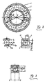
- Figure 4 shows the determination of the nominal pressure angle ⁇ O and the operating pressure angle ⁇ B for angular contact ball bearings.
- f n denotes the rotational frequency of the respective shaft end in the rolling bearing and z the number of rolling elements.
- vibration spectrum can also be generated by suggestions outside of the rolling bearing.
- a typical one Vibration spectrum for a rolling bearing with an accelerometer as FIG. 5 shows the measurement signal pickup.
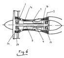
- the aircraft engine shown in Figure 6 consists of a high pressure system 1 and a low pressure system 2 with shafts 3 and 4 for power transmission are equipped.
- the two shafts 3, 4 are not mechanically connected to one another connected and thus rotate independently of each other.
- the low pressure system 2 consists of the fan 2a, the rotor of the booster stage 2b and the low-pressure turbine rotor 2c, which are connected to one another via the shaft 3.
- the high-pressure compressor rotor 1a and the high-pressure turbine rotor 1 b connected together.
- the shaft 3 is on the torque-absorbing side Aggregates in the form of the fan 2a and the booster stage 2b via an as Grooved ball bearing trained roller bearing 6 is mounted.
- the shaft 3 is over a Rolling bearing 7 is supported with cylindrical rolling elements.
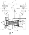
- a separate measuring channel is identical in each case for the two roller bearings 6 and 7 Execution provided. Since only one measurement signal per roller bearing 6 or 7 is required, the two measuring signal recorders 8a and 8b are connected to an OR gate 10 activated. In an analogous manner, the measurement signal pickups 9a and 9b an OR gate 11 responsible.
- OR gates 10 and 11 each leave a complex-period measurement signal in the time domain, which can be assigned to the respective roller bearings 6 and 7.
- t denotes a point in time
- T the period of the periodic function.
- the basic equations for a Fourier-transformed complex-period measurement signal are known to the person skilled in the art and are therefore not given here. It should only be mentioned that the Fourier transformation is carried out by the FFT processors 12 and 13.
- the Fourier-transformed measurement function is now available in the form of the frequency representation. If, on the other hand, the calculation were carried out as a discrete Fourier transformation, the computational effort would no longer be in the real-time capable range. Therefore, recursion formulas are used that reduce the computing effort by a factor of 10 3 . Mature processes for this Fast Fourier transmission are available in different versions. The FFT processors 12 and 13 handle this task in real time.
- the measured value functions which have been subjected to a significant data reduction without loss of information, then pass through the filters 14 and 15.
- These filters 14, 15 are designed such that they can only pass a frequency band from 0 Hz to the maximum frequency which can be followed Equation (C) given above (in connection with FIGS. 2-4), which represents the rollover frequency of the rolling bearing inner ring, is determined.
- the value f n in this equation (C) corresponds to the maximum permissible rotational frequency of the low-pressure turbine rotor 2c.
- the filtering mentioned takes place almost instantaneously under real-time conditions.
- the arithmetic processors 16 and 17 can carry out a comparison of the rotational frequencies for the rolling bearings determined according to equations (A) to (D), a predefined spreading range not being allowed to be exceeded.
- the Gaussian method of least squares is preferably used to determine the effective values f n1 and f n2 and the standard deviations ⁇ 1 and ⁇ 2 of the measurement results, which are then used as the basis for a subsequent evaluation.
- the rotational frequency information is thus in the form ⁇ f n1 ⁇ ⁇ 1 ⁇ and ⁇ f n2 ⁇ ⁇ 2 ⁇ for both roller bearings 6, 7.
- the inflow to the fuel ring line 19 is equipped with a fuel quick-closing valve 20.
- This fuel quick-closing valve 20 which is not provided with an electromagnetic actuator 22, is always kept closed by means of a spring 21 in the electrically de-energized state. If the rotational frequencies f n1 , f n2 or ⁇ f n1 + ⁇ 1 ⁇ , ⁇ f n2 - ⁇ 2 ⁇ of those on both roller bearings 6 and 7 match, the fuel quick-closing valve 20 is thus kept under electrical voltage and is in the open state ,
Landscapes
- Engineering & Computer Science (AREA)
- Mechanical Engineering (AREA)
- General Engineering & Computer Science (AREA)
- Control Of Turbines (AREA)
Description




Für ein Rillenkugellager mit radialer und axialer Belastung gilt für den sog. Betriebsdruckwinkel αB gemäß Figuren 3 und 4 der folgende Zusammenhang:
Die Grundgleichungen für ein fouriertransformiertes komplexperiodisches Meßsignal sind dem entsprechenden Fachmann bekannt und werden daher hier nicht wiedergegeben. Erwähnt sei lediglich, daß die Fouriertansformation durch die FFT-Prozessoren 12 und 13 vorgenommen wird.
- die Rotationsfrequenz des Käfigs,
- die Überrollfrequenz des Außenringes,
- die Überrollfrequenz des Innenringes und
- die Wälzkörperrotationsfrequenz.
Die Fälle {fn1 + σ1} = {fn2 - σ2} und {fn2 + σ2} = {fn1 - σ1} gelten dabei als Grenzfälle der Übereinstimmung.
Sollte allerdings der Vergleich ergeben, daß {fn1 + σ1} kleiner als (<) {fn2 - σ2} ist, so kann davon ausgegangen werden, daß ein Bruch der Welle 3 stattgefunden hat. Dieser Zustand erfordert dann die Einleitung einer drehzahlbegrenzenden Maßnahme, insbesondere die Sicherheitsschnellabschaltung der Brennstoffzufuhr, die mittels einer Bennnstoff-Ringleitung 19 erfolgt.
Bei einer Übereinstimmung der Drehfrequenzen fn1, fn2 bzw. {fn1 + σ1}, {fn2 - σ2} der an beiden Wälzlagern 6 und 7 wird somit das Kraftstoff-Schnellschlußventil 20 unter elektrischer Spannung gehalten und ist im geöffneten Zustand.
- signifikant geringerer Masseeinsatz bei den Bauteilen zur Sicherung der Funktion Drehzahlbegrenzung/Sicherheitsschnellabschaltung bei Wellenbruch zwischen Fan und Niederdruckturbine,
- aufgrund der Masseneinsparung ergeben sich geringere Betriebskosten für Flugtriebwerke,
- besseres Masse-Kostenverhältnis im Vergleich zu mechanisch wirkenden Drehzahlbegrenzungseinrichtungen/Sicherheitsschnellabschaltung,
- Sicherstellung der Funktion ohne unnötige Zerstörung von Bauteilen und Baugruppen zum Aufbau der Zwangskräfte zum Abbremsen und zum Abbau der überschüssigen Rotationsenergie,
- kostengünstiger realisierbar als bestehende mechanische Lösungen,
- Anwendung des Kommonalitätskonzeptes für Hersteller von Triebwerksfamilien
- keine sicherheitsbedingten Kompromisse hinsichtlich der Aerodynamik von Turbinenbeschaufelungen,
- geringere Betriebskosten aufgrund des besseren spezifischen Brennstoffverbrauches bei optimal aerodynamisch gestalteter Beschaufelung der Niederdruckturbine
- das beschriebene Verfahren bzw. eine nach diesem Verfahren arbeitende Vorrichtung ist nachrüstbar.
Claims (11)
- Verfahren zum Erkennen eines Wellenbruches in einer Strömungskraftmaschine mit dem Ziel, danach eine geeignete drehzahlbegrenzende Maßnahme, insbesondere eine Brennstoffschnellabschaltung bei einer Flug-Gasturbinenanlage, einzuleiten, wobei ein drehmomentabgebender Turbinenläufer und ein drehmomentaufnehmendes Aggregat über die hinsichtlich eines Bruches zu überwachende, im wesentlichen endseitig in zumindest zwei Wälzlagern (6, 7) gelagerte Welle (3) miteinander verbunden sind, wobei die Drehfrequenzen (fn1; fn2) der beiden Wellenenden in den Wälzlagern (6, 7) kontinuierlich und im wesentlichen in Echtzeit ermittelt und miteinander verglichen werden, und dass bei einer gegenüber der Drehfrequenz (fn1) am Wälzlager (6) des drehmomentaufnehmenden Aggregates höheren Drehfrequenz (fn2) am turbinenläuferseitigen Wälzlager (7) auf einen Bruch der Welle (3) geschlossen wird,
dadurch gekennzeichnet, dass über eine Filtereinheit (14, 15) echtzeitgerecht für beide Wälzlager (6, 7) die Rotationsfrequenz des Wälzlager-Käfigs und/oder die Überrollfrequenz des Wälzlager-Außenrings und/oder die Überrollfrequenz des Wälzlager-Innenrings und/oder die Wälzkörperrotationsfrequenz festgestellt und hieraus die Drehfrequenzen (fn1; fn2) der in den Wälzlagern (6, 7) gelagerten Wellenenden bestimmt werden. - Verfahren nach Anspruch 1, dadurch gekennzeichnet, dass echtzeitgerecht mittels eines Arithmetik-Prozessors (16, 17) für beide Wälzlager (6, 7) über getrennte Messkanäle die Bestimmung der Drehfrequenz (fn1; fn2) des jeweiligen Wellenendes unter Rückgriff auf eine oder mehrere typische wälzlagerfrequenzen erfolgt, die von den Wälzlagern (6, 7) bei deren Rotation emittiert werden.
- Verfahren nach Anspruch 2, dadurch gekennzeichnet, dass bei Verwendung von mehr als einer typischen Wälzlagerfrequenz die Bestimmung der Drehfrequenzen (fn1; fn2) nach der Gauß'schen Methode der kleinsten Fehlerquadrate in der Form (fn1±σ1) und (fn2±σ2) erfolgt.
- Verfahren nach einem der Ansprüche 1 bis 3, dadurch gekennzeichnet, dass für jedes Wälzlager (6, 7) ein getrennt funktionierender Messkanal zur Bestimmung der Drehfrequenz (fn1; fn2) des jeweiligen Wellenendes in den Wälzlagern (6, 7) vorhanden ist und die beiden Messkanäle in einem Komparator (18) zwecks Vergleiches der Drehfrequenzen (fn1; fn2) zusammengeführt werden.
- Verfahren nach einem der Ansprüche 1 bis 4, dadurch gekennzeichnet, dass das an den Wälzlagern (6, 7) mittels Messsignalaufnehmern (8a, 8b, 9a, 9c) ermittelte Messsignal eine Redundanz in der Messinformation enthält und vorzugsweise ein komplex-periodisches Signal ist.
- Verfahren nach Anspruch 5, dadurch gekennzeichnet, dass das komplexperiodische Messsignal {f(t)=f(t+nT) mit n = 0; 1; 2 ...} vom Zeitbereich in den Frequenzbereich mittels Fast Fourier Transmission echtzeitgerecht in ein Amplitudenspektrum überführt wird.
- Verfahren nach einem der Ansprüche 1 bis 6, dadurch gekennzeichnet, dass im möglichen Drehzahlbereich der beiden Wälzlager (6, 7) bei Auftreten einer signifikanten Differenz zwischen den beiden Drehfrequenzen (fn1; fn2) ein Schnellschluss eines ansonsten unter elektrischer Spannung stehenden und dabei geöffneten Brennstoffschnellschlussventils (20) durch unverzügliche Spannungslosschaltung erfolgt.
- Verfahren nach Anspruch 7,
dadurch gekennzeichnet, dass im möglichen Drehzahlbereich der beiden Wälzlager (6, 7) von {fn2 + σ2 = fn1 - σ1} bis {fn1 + σ1 = fn2- σ2} das Brennstoffschnellschlussventil (20) unter elektrischer Spannung steht und geöffnet ist und dass ein Schnellschluss des Brennstoffschnellschlussventils (20) durch unverzügliche Spannungslosschaltung erfolgt, wenn die Bedingung {fn1 + σ1 < fn2 - σ2} erfüllt ist. - Vorrichtung zur Durchführung des Verfahrens nach einem der vorangegangenen Ansprüche, wobei an beiden Wälzlagern (6, 7) jeweils zumindest zwei Messsignalaufnehmer (8a, 8b, 9a, 9c) angebracht sind, deren Anordnung und Funktion je Wälzlager (6, 7) redundant ausgeführt ist und wobei es sich bei den Messsignalaufnehmern (8a, 8b, 9a, 9c) um Geschwindigkeits- oder Beschleunigungsaufnehmer jeweils gleichen Typs handelt.
- Vorrichtung zur Durchführung des Verfahrens nach Anspruch 9, wobei das drehmomentaufnehmende Aggregat (6) ein Verdichter, ein Fan, ein Booster, ein Propeller oder eine Kombination hiervon ist.
- Vorrichtung zur Durchführung des Verfahrens nach Anspruch 9 oder 10, wobei das Brennstoff-Schnellschlussventil (20) federbelastet ist und mittels einer stromdurchflossenen elektromagnetischen Stelleinrichtung (22) im geöffneten Zustand gehalten wird.
Applications Claiming Priority (3)
| Application Number | Priority Date | Filing Date | Title |
|---|---|---|---|
| DE19857552 | 1998-12-14 | ||
| DE19857552A DE19857552A1 (de) | 1998-12-14 | 1998-12-14 | Verfahren zum Erkennen eines Wellenbruches in einer Strömungskraftmaschine |
| PCT/EP1999/008717 WO2000036280A1 (de) | 1998-12-14 | 1999-11-12 | Verfahren zum erkennen eines wellenbruches in einer strömungskraftmaschine |
Publications (2)
| Publication Number | Publication Date |
|---|---|
| EP1055052A1 EP1055052A1 (de) | 2000-11-29 |
| EP1055052B1 true EP1055052B1 (de) | 2004-06-02 |
Family
ID=7890982
Family Applications (1)
| Application Number | Title | Priority Date | Filing Date |
|---|---|---|---|
| EP99955983A Expired - Lifetime EP1055052B1 (de) | 1998-12-14 | 1999-11-12 | Verfahren zum erkennen eines wellenbruches in einer strömungskraftmaschine |
Country Status (4)
| Country | Link |
|---|---|
| US (1) | US6494046B1 (de) |
| EP (1) | EP1055052B1 (de) |
| DE (2) | DE19857552A1 (de) |
| WO (1) | WO2000036280A1 (de) |
Families Citing this family (48)
| Publication number | Priority date | Publication date | Assignee | Title |
|---|---|---|---|---|
| SE0101984D0 (sv) * | 2001-05-31 | 2001-05-31 | Skf Ab | A device, computer program product and method for indicating a function deviation of one or more details of manufacturing equipment using frequency component analyses |
| DE10207455B4 (de) * | 2002-02-22 | 2006-04-20 | Framatome Anp Gmbh | Verfahren und Einrichtung zur Detektion einer impulsartigen mechanischen Einwirkung auf ein Anlagenteil |
| DE10310900A1 (de) | 2003-03-13 | 2004-09-23 | Rolls-Royce Deutschland Ltd & Co Kg | Elekronisches Sicherheitssystem zur Vermeidung eines Überdrehzahlzustandes bei einem Wellenbruch |
| DE102004026366A1 (de) * | 2004-05-29 | 2005-12-15 | Mtu Aero Engines Gmbh | Einrichtung zur Detektion eines Wellenbruchs an einer Gasturbine sowie Gasturbine |
| DE102004033924A1 (de) * | 2004-07-14 | 2006-02-09 | Mtu Aero Engines Gmbh | Einrichtung zur Detektion eines Wellenbruchs an einer Gasturbine sowie Gasturbine |
| DE102004047892A1 (de) * | 2004-10-01 | 2006-04-06 | Mtu Aero Engines Gmbh | Gasturbine und Verfahren zum Abschalten einer Gasturbine bei Identifikation eines Wellenbruchs |
| RU2293851C1 (ru) * | 2005-07-06 | 2007-02-20 | Государственное Унитарное Предприятие Тушинское Машиностроительное Конструкторское Бюро "Союз" (Гуп Тмкб "Союз") | Способ ресурсосберегающей эксплуатации газотурбинных двигателей |
| US8191399B2 (en) | 2005-12-16 | 2012-06-05 | Siemens Aktiengesellschaft | Monitoring device and monitoring method for a drive device |
| DE102006004947B4 (de) | 2006-02-03 | 2007-12-27 | Areva Np Gmbh | Verfahren und Einrichtung zur Detektion einer impulsartigen mechanischen Einwirkung auf ein Anlagenteil |
| DE102006004941B4 (de) * | 2006-02-03 | 2008-01-10 | Areva Np Gmbh | Verfahren und Einrichtung zur Detektion des Ortes einer impulsartigen mechanischen Einwirkung auf ein Anlagenteil |
| US8818683B2 (en) * | 2006-04-21 | 2014-08-26 | General Electric Company | Method and apparatus for operating a gas turbine engine |
| FR2907839B1 (fr) * | 2006-10-25 | 2011-06-17 | Snecma | Methode pour reduire la vitesse en cas de rupture d'arbre de turbine de moteur a turbine a gaz |
| FR2916482B1 (fr) | 2007-05-25 | 2009-09-04 | Snecma Sa | Systeme de freinage en cas de rupture d'arbre de turbine dans un moteur a turbine a gaz |
| FR2916483B1 (fr) | 2007-05-25 | 2013-03-01 | Snecma | Systeme de dissipation d'energie en cas de rupture d'arbre de turbine dans un moteur a turbine a gaz |
| FR2923540B1 (fr) * | 2007-11-13 | 2010-01-29 | Snecma | Dispositif de detection de rupture d'un arbre de turbomachine |
| DE102008007519A1 (de) | 2008-02-05 | 2009-08-13 | Nordex Energy Gmbh | Vorrichtung zur Überwachung der Drehzahl bei einer Windenergieanlage |
| EP2131178B1 (de) * | 2008-06-02 | 2011-04-06 | Siemens Aktiengesellschaft | Diagnoseverfahren für zumindest ein Kugellager, insbesondere für ein Schrägkugellager, korrespondierendes Diagnosesystem sowie Verwendung eines derartigen Diagnosesystems |
| FR2939924B1 (fr) * | 2008-12-15 | 2012-10-12 | Snecma | Identification de defaillances dans un moteur d'aeronef |
| US8752394B2 (en) * | 2010-03-15 | 2014-06-17 | Rolls-Royce Corporation | Determining fan parameters through pressure monitoring |
| GB2488805A (en) * | 2011-03-09 | 2012-09-12 | Rolls Royce Plc | Shaft break detection |
| GB201120511D0 (en) | 2011-11-29 | 2012-01-11 | Rolls Royce Plc | Shaft break detection |
| GB201121639D0 (en) * | 2011-12-16 | 2012-01-25 | Rolls Royce Plc | Shaft break detection |
| FR2987085B1 (fr) * | 2012-02-20 | 2014-03-21 | Snecma | Procede de securisation du fonctionnement d'une turbomachine |
| SG11201405922SA (en) * | 2012-04-05 | 2014-10-30 | United Technologies Corp | Geared turbofan gas turbine engine with reliability check on gear connection |
| US20140178175A1 (en) * | 2012-12-21 | 2014-06-26 | United Technologies Corporation | Air turbine starter monitor system |
| EP3014089B1 (de) * | 2013-06-24 | 2019-06-12 | United Technologies Corporation | Übermässige verformungsüberwachung anhand eines lüfterantriebssystems |
| US10048144B2 (en) * | 2013-07-12 | 2018-08-14 | Pratt & Whitney Canada Corp. | Method and system for applying a compressive preload |
| US10012275B2 (en) * | 2014-04-16 | 2018-07-03 | Schaeffler Technologies AG & Co. KG | Method for configuring a software damper of a clutch control system and software damper for damping chatter vibrations |
| US9708927B2 (en) | 2014-07-09 | 2017-07-18 | Siemens Energy, Inc. | Optical based system and method for monitoring turbine engine blade deflection |
| ES2780689T3 (es) * | 2014-10-01 | 2020-08-26 | Ge Renewable Tech | Máquina rotativa e instalación para convertir energía que comprende tal máquina |
| EP3040520B1 (de) * | 2015-01-05 | 2019-07-03 | Rolls-Royce PLC | Turbinenmotor-wellenbrucherkennung |
| US9663278B1 (en) | 2015-12-16 | 2017-05-30 | II Harold C. Daws | Container with improved locking system |
| US10228305B2 (en) | 2016-01-18 | 2019-03-12 | Pratt & Whitney Canada Corp. | Shaft shear detection through shaft oscillation |
| US10228304B2 (en) * | 2016-01-18 | 2019-03-12 | Pratt & Whitney Canada Corp. | Shaft shear detection through shaft oscillation |
| US10180078B2 (en) | 2016-06-17 | 2019-01-15 | Pratt & Whitney Canada Corp. | Shaft shear detection in gas turbine engines |
| GB201611674D0 (en) * | 2016-07-05 | 2016-08-17 | Rolls Royce Plc | A turbine arrangement |
| US10989063B2 (en) * | 2016-08-16 | 2021-04-27 | Honeywell International Inc. | Turbofan gas turbine engine shaft break detection system and method |
| US10316689B2 (en) | 2016-08-22 | 2019-06-11 | Rolls-Royce Corporation | Gas turbine engine health monitoring system with shaft-twist sensors |
| EP3330494B1 (de) * | 2016-12-02 | 2019-11-27 | Rolls-Royce Deutschland Ltd & Co KG | Anordnung, turbomaschine und verfahren zur erkennung eines wellenbruchs |
| EP3330493B1 (de) * | 2016-12-02 | 2019-05-01 | Rolls-Royce Deutschland Ltd & Co KG | Steuerungssystem und -verfahren für einen gasturbinenmotor |
| US10436060B2 (en) * | 2016-12-09 | 2019-10-08 | Pratt & Whitney Canada Corp. | Shaft event detection in gas turbine engines |
| US11136134B2 (en) * | 2018-12-21 | 2021-10-05 | Pratt & Whitney Canada Corp. | System and method for operating a gas turbine engine coupled to an aircraft propeller |
| CN109578795B (zh) * | 2019-01-30 | 2023-10-20 | 潍柴动力扬州柴油机有限责任公司 | 一种十字万向轴防飞脱装置 |
| US11333035B2 (en) * | 2019-07-24 | 2022-05-17 | Pratt & Whitney Canada Corp. | Shaft shear detection in a gas turbine engine |
| GB2593689A (en) | 2020-03-30 | 2021-10-06 | Rolls Royce Plc | Gas turbine engine |
| FR3111668B1 (fr) * | 2020-06-17 | 2023-04-07 | Airbus Helicopters | Procédé pour arrêter un moteur en survitesse, système et giravion associés |
| IT202000028520A1 (it) | 2020-11-26 | 2022-05-26 | Ge Avio Srl | Sistema e metodo per la mitigazione di velocita' eccessiva di rotore |
| CN114017267B (zh) * | 2021-11-16 | 2024-06-11 | 西安热工研究院有限公司 | 一种风力发电机组变桨轴承故障诊断方法及系统 |
Family Cites Families (11)
| Publication number | Priority date | Publication date | Assignee | Title |
|---|---|---|---|---|
| US3963372A (en) * | 1975-01-17 | 1976-06-15 | General Motors Corporation | Helicopter power plant control |
| JPS5444106A (en) * | 1977-09-14 | 1979-04-07 | Hitachi Ltd | Speed controlling method for steam turbine |
| JPS54111871A (en) * | 1978-02-22 | 1979-09-01 | Hitachi Ltd | Frequency detecting method |
| US4217617A (en) * | 1978-09-22 | 1980-08-12 | General Electric Company | Turbine trip circuit |
| AT370851B (de) * | 1980-07-07 | 1983-05-10 | Simmering Graz Pauker Ag | Turbinen-regel- und schutzsystem |
| US4712372A (en) * | 1985-09-18 | 1987-12-15 | Avco Corporation | Overspeed system redundancy monitor |
| JPH04287803A (ja) * | 1991-03-19 | 1992-10-13 | Hitachi Ltd | タービン過速度防止装置 |
| NL9401949A (nl) | 1994-11-22 | 1996-07-01 | Skf Ind Trading & Dev | Werkwijze voor het analyseren van regelmatig geëxciteerde mechanische trillingen. |
| DE19524992C1 (de) * | 1995-07-08 | 1996-08-08 | Mtu Muenchen Gmbh | Regelung eines Wellentriebwerks mit einem Mikrosteuergerät |
| US5804726A (en) | 1995-10-16 | 1998-09-08 | Mtd Products Inc. | Acoustic signature analysis for a noisy enviroment |
| DE19727296A1 (de) * | 1997-06-27 | 1999-01-07 | Mtu Muenchen Gmbh | Einrichtung zur Notabschaltung einer Gasturbine |
-
1998
- 1998-12-14 DE DE19857552A patent/DE19857552A1/de not_active Withdrawn
-
1999
- 1999-11-12 EP EP99955983A patent/EP1055052B1/de not_active Expired - Lifetime
- 1999-11-12 US US09/622,026 patent/US6494046B1/en not_active Expired - Lifetime
- 1999-11-12 WO PCT/EP1999/008717 patent/WO2000036280A1/de not_active Ceased
- 1999-11-12 DE DE59909646T patent/DE59909646D1/de not_active Expired - Lifetime
Also Published As
| Publication number | Publication date |
|---|---|
| DE59909646D1 (de) | 2004-07-08 |
| WO2000036280A1 (de) | 2000-06-22 |
| US6494046B1 (en) | 2002-12-17 |
| DE19857552A1 (de) | 2000-06-15 |
| EP1055052A1 (de) | 2000-11-29 |
Similar Documents
| Publication | Publication Date | Title |
|---|---|---|
| EP1055052B1 (de) | Verfahren zum erkennen eines wellenbruches in einer strömungskraftmaschine | |
| DE69910022T2 (de) | Vorrichtung zur erkennung eines wellenbruchs | |
| EP2171216B1 (de) | Regelung für eine gasturbine mit aktiv stabilisiertem verdichter | |
| EP2404059B1 (de) | Verfahren zum überwachen von windturbinen | |
| DE3686122T2 (de) | Testgeraet fuer duesenmotor. | |
| DE102011008561A1 (de) | Funktionsüberwachtes Führungssystem zur Verstellung zumindest einer Systemkomponente sowie Verfahren zur Funktionsüberwachung eines solchen Führungssystems | |
| EP2678654B1 (de) | Verfahren für die funktionsprüfung von turbomaschinen, sowie prüfeinrichtung dafür | |
| DE2635993B2 (de) | Brennstoffregelung für eine Gasturbinenanlage | |
| EP2805058B1 (de) | VERFAHREN ZUR VERMEIDUNG VON PUMPSTÖßEN IN EINEM VERDICHTER | |
| EP3061954B1 (de) | Verfahren und vorrichtung zur ansteuerung eines antriebssystems eines kraftfahzeugs mit einer aufgeladenen brennkraftmaschine | |
| DE102016209262A1 (de) | Einstellvorrichtung und Einstellverfahren einer Axiallast in einem Flugzeugtriebwerk | |
| DE102010009941A1 (de) | Verfahren zum Überwachen von Windturbinen | |
| DE69203063T2 (de) | Schutzsystem gegen die Löschung einer Turbomaschine bei Eindrigen von Wasser oder Hagel. | |
| EP3617481B1 (de) | Überwachung von servoventil-filterelementen | |
| DE69623098T2 (de) | Vermeidung des pumpens eines verdichters | |
| DE102019201788A1 (de) | Verfahren zum Betreiben eines Abgasturboladers | |
| EP2619461B1 (de) | Vorrichtung und verfahren zum sicheren betreiben eines verdichters an der pumpgrenze | |
| DE102008002610A1 (de) | Verfahren zur (Online-) Betriebsüberwachung und Regelung einer Gasturbinenanlage | |
| EP3238338B1 (de) | Verfahren sowie vorrichtung zum überwachen des betriebes einer stromerzeugungsanlage | |
| EP2984301B1 (de) | Verfahren zum testen eines überdrehzahlschutzes einer gud-einwellenanlage | |
| DE102016215125A1 (de) | Verfahren zur Steuerung einer Notfalleinrichtung und Klappensteuergerät | |
| EP1792242A1 (de) | Verfahren und vorrichtung zum ermitteln eines fehlerzustandes eines rotierenden verdichters | |
| DE102008036305A1 (de) | Verfahren zum Betreiben eines Verdichters | |
| DE102024205024A1 (de) | Verfahren zum Erkennen einer Reibungsänderung bei einer gelagerten Welle ei-nes technischen Systems | |
| RU133206U1 (ru) | Устройство диагностики положения направляющих аппаратов осевого компрессора |
Legal Events
| Date | Code | Title | Description |
|---|---|---|---|
| PUAI | Public reference made under article 153(3) epc to a published international application that has entered the european phase |
Free format text: ORIGINAL CODE: 0009012 |
|
| 17P | Request for examination filed |
Effective date: 20000518 |
|
| AK | Designated contracting states |
Kind code of ref document: A1 Designated state(s): AT BE CH CY DE DK ES FI FR GB GR IE IT LI LU MC NL PT SE |
|
| 17Q | First examination report despatched |
Effective date: 20030626 |
|
| GRAP | Despatch of communication of intention to grant a patent |
Free format text: ORIGINAL CODE: EPIDOSNIGR1 |
|
| GRAS | Grant fee paid |
Free format text: ORIGINAL CODE: EPIDOSNIGR3 |
|
| GRAA | (expected) grant |
Free format text: ORIGINAL CODE: 0009210 |
|
| AK | Designated contracting states |
Kind code of ref document: B1 Designated state(s): DE FR GB |
|
| REG | Reference to a national code |
Ref country code: GB Ref legal event code: FG4D Free format text: NOT ENGLISH |
|
| REF | Corresponds to: |
Ref document number: 59909646 Country of ref document: DE Date of ref document: 20040708 Kind code of ref document: P |
|
| REG | Reference to a national code |
Ref country code: IE Ref legal event code: FG4D Free format text: GERMAN |
|
| RAP2 | Party data changed (patent owner data changed or rights of a patent transferred) |
Owner name: ROLLS-ROYCE DEUTSCHLAND GMBH |
|
| RAP2 | Party data changed (patent owner data changed or rights of a patent transferred) |
Owner name: ROLLS-ROYCE DEUTSCHLAND LTD & CO KG |
|
| GBT | Gb: translation of ep patent filed (gb section 77(6)(a)/1977) |
Effective date: 20041206 |
|
| ET | Fr: translation filed | ||
| PLBE | No opposition filed within time limit |
Free format text: ORIGINAL CODE: 0009261 |
|
| STAA | Information on the status of an ep patent application or granted ep patent |
Free format text: STATUS: NO OPPOSITION FILED WITHIN TIME LIMIT |
|
| 26N | No opposition filed |
Effective date: 20050303 |
|
| REG | Reference to a national code |
Ref country code: FR Ref legal event code: CJ Ref country code: FR Ref legal event code: CD Ref country code: FR Ref legal event code: CA |
|
| PGFP | Annual fee paid to national office [announced via postgrant information from national office to epo] |
Ref country code: DE Payment date: 20091127 Year of fee payment: 11 |
|
| PGFP | Annual fee paid to national office [announced via postgrant information from national office to epo] |
Ref country code: GB Payment date: 20091125 Year of fee payment: 11 Ref country code: FR Payment date: 20091201 Year of fee payment: 11 |
|
| GBPC | Gb: european patent ceased through non-payment of renewal fee |
Effective date: 20101112 |
|
| REG | Reference to a national code |
Ref country code: DE Ref legal event code: R119 Ref document number: 59909646 Country of ref document: DE Effective date: 20110601 Ref country code: DE Ref legal event code: R119 Ref document number: 59909646 Country of ref document: DE Effective date: 20110531 |
|
| REG | Reference to a national code |
Ref country code: FR Ref legal event code: ST Effective date: 20110801 |
|
| PG25 | Lapsed in a contracting state [announced via postgrant information from national office to epo] |
Ref country code: DE Free format text: LAPSE BECAUSE OF NON-PAYMENT OF DUE FEES Effective date: 20110531 |
|
| PG25 | Lapsed in a contracting state [announced via postgrant information from national office to epo] |
Ref country code: FR Free format text: LAPSE BECAUSE OF NON-PAYMENT OF DUE FEES Effective date: 20101130 |
|
| PG25 | Lapsed in a contracting state [announced via postgrant information from national office to epo] |
Ref country code: GB Free format text: LAPSE BECAUSE OF NON-PAYMENT OF DUE FEES Effective date: 20101112 |