EP1055075B1 - Connecteur a rivet aveugle - Google Patents
Connecteur a rivet aveugle Download PDFInfo
- Publication number
- EP1055075B1 EP1055075B1 EP99905063A EP99905063A EP1055075B1 EP 1055075 B1 EP1055075 B1 EP 1055075B1 EP 99905063 A EP99905063 A EP 99905063A EP 99905063 A EP99905063 A EP 99905063A EP 1055075 B1 EP1055075 B1 EP 1055075B1
- Authority
- EP
- European Patent Office
- Prior art keywords
- connector
- bore
- connector according
- rivet
- peripheral region
- Prior art date
- Legal status (The legal status is an assumption and is not a legal conclusion. Google has not performed a legal analysis and makes no representation as to the accuracy of the status listed.)
- Expired - Lifetime
Links
Images
Classifications
-
- F—MECHANICAL ENGINEERING; LIGHTING; HEATING; WEAPONS; BLASTING
- F16—ENGINEERING ELEMENTS AND UNITS; GENERAL MEASURES FOR PRODUCING AND MAINTAINING EFFECTIVE FUNCTIONING OF MACHINES OR INSTALLATIONS; THERMAL INSULATION IN GENERAL
- F16B—DEVICES FOR FASTENING OR SECURING CONSTRUCTIONAL ELEMENTS OR MACHINE PARTS TOGETHER, e.g. NAILS, BOLTS, CIRCLIPS, CLAMPS, CLIPS OR WEDGES; JOINTS OR JOINTING
- F16B19/00—Bolts without screw-thread; Pins, including deformable elements; Rivets
- F16B19/04—Rivets; Spigots or the like fastened by riveting
- F16B19/08—Hollow rivets; Multi-part rivets
- F16B19/10—Hollow rivets; Multi-part rivets fastened by expanding mechanically
- F16B19/1027—Multi-part rivets
- F16B19/1036—Blind rivets
- F16B19/1045—Blind rivets fastened by a pull - mandrel or the like
- F16B19/1072—Blind rivets fastened by a pull - mandrel or the like the pull-mandrel or the like comprising a thread and being rotated with respect to the rivet, thereby mechanically expanding and fastening the rivet
-
- F—MECHANICAL ENGINEERING; LIGHTING; HEATING; WEAPONS; BLASTING
- F16—ENGINEERING ELEMENTS AND UNITS; GENERAL MEASURES FOR PRODUCING AND MAINTAINING EFFECTIVE FUNCTIONING OF MACHINES OR INSTALLATIONS; THERMAL INSULATION IN GENERAL
- F16B—DEVICES FOR FASTENING OR SECURING CONSTRUCTIONAL ELEMENTS OR MACHINE PARTS TOGETHER, e.g. NAILS, BOLTS, CIRCLIPS, CLAMPS, CLIPS OR WEDGES; JOINTS OR JOINTING
- F16B33/00—Features common to bolt and nut
- F16B33/002—Means for preventing rotation of screw-threaded elements
-
- F—MECHANICAL ENGINEERING; LIGHTING; HEATING; WEAPONS; BLASTING
- F16—ENGINEERING ELEMENTS AND UNITS; GENERAL MEASURES FOR PRODUCING AND MAINTAINING EFFECTIVE FUNCTIONING OF MACHINES OR INSTALLATIONS; THERMAL INSULATION IN GENERAL
- F16B—DEVICES FOR FASTENING OR SECURING CONSTRUCTIONAL ELEMENTS OR MACHINE PARTS TOGETHER, e.g. NAILS, BOLTS, CIRCLIPS, CLAMPS, CLIPS OR WEDGES; JOINTS OR JOINTING
- F16B5/00—Joining sheets or plates, e.g. panels, to one another or to strips or bars parallel to them
- F16B5/02—Joining sheets or plates, e.g. panels, to one another or to strips or bars parallel to them by means of fastening members using screw-thread
- F16B5/025—Joining sheets or plates, e.g. panels, to one another or to strips or bars parallel to them by means of fastening members using screw-thread specially designed to compensate for misalignement or to eliminate unwanted play
Definitions
- This invention relates to blind rivet connectors and in particular, but not exclusively, to blind internally threaded rivets otherwise known as rivet nuts or "rivnuts".
- FR-A-2721967 and DE-B-1286812 both disclose blind rivets connecting two components together and using a non deformable collar around the rivet to prevent the components from being gripped too tightly by the rivet, whereby some radial play may take place , but no internal releasable engagement configuration within the meaning of appended claim 1 is present.
- a nut connector permitting some radial float is known, for example, from US-A- 4 919 578 which, however, discloses no resilient peripheral region adjacent the head region of the connector.
- this invention provides a blind rivet connector for being passed through a bore of a pre-determined diameter in a workpiece and clinched to prevent withdrawal, said connector comprising:
- the resilient peripheral region may be provided by means of locally thickening and/or locally hardening the material
- the resilient peripheral region preferably comprises a separate relatively non-deformable collar of diameter less than that of the bore but of equal or greater axial dimension.
- the rivet can incorporate various types of internal releasable engagement configuration, but it is preferred for the connector to incorporate an internal thread.
- this invention provides an internally threaded blind rivet nut including adjacent the clinchable region thereof a resilient collar or peripheral region dimensioned such that in use, when said rivet nut is clinched it is capable of limited axial and/or radial float.
- the invention also extends to an assembly comprising at least two components connected by means of the connector or rivet nut as described above.
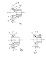
- the rivet connector comprises a faceplate or reaction head 10 having an anti-rotation pin 12.
- a body of the rivet connector forms a generally tubular portion 26, comprising an internally releasable engagement configuration in the form of an internally threaded end portion 14 and a local plastically deformable region 16 intermediate the threaded end portion 14 and the faceplate 10.
- the rivet connector is modified by means of a resilient peripheral region in the form of a hard, substantially non-deformable collar 18 which fits snugly around the outside of the tubular portion 26, adjacent the face plate 10.
- the outer diameter of the collar 18 and its axial dimension are selected to be slightly less and slightly greater respectively than the diameter of the rivet body and the material thickness of a bore of the hole 20 through an associated component 28 through which the rivet connector is to be passed.
- the associated component 28 also includes adjacent the hole 20 a smaller non-rotation hole 22 which receives the pin 12 of the faceplate 10. This arrangement may however be modified as required; for example, as shown in Figure 3, the pin 12 may be replaced by an integrally formed tang 24.
- a threaded mandrel (not shown) is screwed into engagement with the threaded portion 14 and a tensile force applied which is reacted by the faceplate 10 of the rivet connector thereby to compress the plastically deformable region 16 to cause it to bulge out and clinch.
- the clinching is controlled by the presence of the collar 18 so that the excrescent material does not foul the periphery of the hole 20 so that, after clinching, the connector has limited axial and radial float.
Landscapes
- Engineering & Computer Science (AREA)
- General Engineering & Computer Science (AREA)
- Mechanical Engineering (AREA)
- Insertion Pins And Rivets (AREA)
- Dowels (AREA)
- Connection Of Plates (AREA)
Claims (7)
- Un connecteur à rivet aveugle destiné à être passé au travers d'un alésage (20) d'un diamètre prédéterminé dans une pièce à usiner (28) et rivé pour empêcher le retrait, ledit connecteur comportant :une portion de tête de réaction agrandie (10) destinée à être retenue par la surface de la pièce à usiner (28) sur un côté de l'alésage (20) ;une portion tubulaire (26) capable de passer au travers dudit alésage (20) et comprenant :grâce auxquelles, à l'utilisation, l'application de compression pour river ledit connecteur amène ladite zone déformable de façon plastique (16) à se déformer de façon plastique, et ladite zone périphérique résiliente (18) est dimensionnée pour permettre une déformation plastique suffisante pour empêcher l'enlèvement ultérieur dudit connecteur mais pour empêcher le sertissage étroit du connecteur autour de la périphérie de l'alésage (20), grâce à quoi le connecteur sera capable de flottement radial restreint relativement audit alésage.à distance de ladite portion de tête (10), une portion d'extrémité (14) incorporant une configuration de mise en prise libérable interne,une zone déformable de façon plastique (16) intermédiaire entre ladite portion d'extrémité et ladite portion de tête, etune zone périphérique résiliente (18) adjacente à ladite zone de tête (10),
- Un connecteur selon la revendication 1 dans lequel la zone périphérique résiliente (18) est dimensionnée de façon à ce que le connecteur soit capable de flottement axial restreint relativement à l'alésage.
- Un connecteur selon la revendication 2, dans lequel ladite zone périphérique résiliente comporte un collier distinct relativement non déformable (18) de diamètre inférieur audit alésage (20) et de dimension axiale égale ou supérieure à celle dudit alésage.
- Un connecteur selon n'importe quelle revendication précédente, dans lequel ladite configuration de mise en prise libérable interne comporte une portion à filetage de vis interne (14).
- Un connecteur selon n'importe quelle revendication précédente comprenant un tenon anti-rotation (24) destiné à se mettre en prise avec le composant (28).
- Un assemblage comportant un composant (28) ayant, inséré dans celui-ci, un connecteur à rivet selon n'importe quelle revendication précédente.
- Un assemblage comportant deux composants (28) connectés entre eux au moyen d'un connecteur à rivet selon n'importe lesquelles des revendications 1 à 5.
Applications Claiming Priority (3)
| Application Number | Priority Date | Filing Date | Title |
|---|---|---|---|
| GBGB9803314.5A GB9803314D0 (en) | 1998-02-18 | 1998-02-18 | Blind rivet connector |
| GB9803314 | 1998-02-18 | ||
| PCT/GB1999/000478 WO1999042734A1 (fr) | 1998-02-18 | 1999-02-15 | Connecteur a rivet aveugle |
Publications (2)
| Publication Number | Publication Date |
|---|---|
| EP1055075A1 EP1055075A1 (fr) | 2000-11-29 |
| EP1055075B1 true EP1055075B1 (fr) | 2003-12-10 |
Family
ID=10827119
Family Applications (1)
| Application Number | Title | Priority Date | Filing Date |
|---|---|---|---|
| EP99905063A Expired - Lifetime EP1055075B1 (fr) | 1998-02-18 | 1999-02-15 | Connecteur a rivet aveugle |
Country Status (6)
| Country | Link |
|---|---|
| EP (1) | EP1055075B1 (fr) |
| AU (1) | AU2536399A (fr) |
| DE (1) | DE69913493T2 (fr) |
| ES (1) | ES2209396T3 (fr) |
| GB (1) | GB9803314D0 (fr) |
| WO (1) | WO1999042734A1 (fr) |
Families Citing this family (7)
| Publication number | Priority date | Publication date | Assignee | Title |
|---|---|---|---|---|
| DE102006023320A1 (de) * | 2006-05-18 | 2007-11-22 | Fischerwerke Artur Fischer Gmbh & Co. Kg | Schraubblindniet, Verbindungsanordnung mit dem Schraubblindniet und Verfahren zum Verbinden mit dem Schraubblindniet |
| DE102014018159A1 (de) | 2014-12-10 | 2016-06-16 | Kvt-Fastening Ag | Blindnietelement, dessen Herstellung und Verwendung |
| FR3032246B1 (fr) * | 2015-01-30 | 2017-08-04 | Bollhoff Otalu Sa | Ecrou a sertir et ensemble de fixation comprenant un tel ecrou |
| WO2016134488A1 (fr) | 2015-02-27 | 2016-09-01 | Selfrag Ag | Procédé et dispositif de fragmentation et/ou d'affaiblissement de matériau en vrac au moyen de décharges à haute tension |
| EP3261768B1 (fr) | 2015-02-27 | 2019-09-11 | Selfrag AG | Procédé et dispositif de fragmentation et/ou d'affaiblissement d'un matériau coulant au moyen d'une décharge à haute tension |
| CA2976964C (fr) | 2015-02-27 | 2023-05-23 | Selfrag Ag | Procede et dispositif de fragmentation et / ou d'affaiblissement d'un materiau coulant au moyen de decharges a haute tension |
| CN112896802B (zh) * | 2021-02-02 | 2023-09-29 | 江苏金之幕建筑智能科技有限公司 | 一种幕墙系统用易收纳弹性插销 |
Family Cites Families (3)
| Publication number | Priority date | Publication date | Assignee | Title |
|---|---|---|---|---|
| DE1286812B (de) * | 1964-06-04 | 1969-01-09 | Honsel Nieten & Metallwarenfab | Blindnietanordnung |
| US4919578A (en) * | 1988-06-09 | 1990-04-24 | Martin Marietta | Rivetless nut plate and fastener |
| FR2721967B1 (fr) * | 1994-07-04 | 1997-01-31 | Sofedit | Articulation perfectionnee pour dispositif d'arret de porte et procede de montage |
-
1998
- 1998-02-18 GB GBGB9803314.5A patent/GB9803314D0/en not_active Ceased
-
1999
- 1999-02-15 DE DE69913493T patent/DE69913493T2/de not_active Expired - Lifetime
- 1999-02-15 WO PCT/GB1999/000478 patent/WO1999042734A1/fr not_active Ceased
- 1999-02-15 ES ES99905063T patent/ES2209396T3/es not_active Expired - Lifetime
- 1999-02-15 AU AU25363/99A patent/AU2536399A/en not_active Abandoned
- 1999-02-15 EP EP99905063A patent/EP1055075B1/fr not_active Expired - Lifetime
Also Published As
| Publication number | Publication date |
|---|---|
| EP1055075A1 (fr) | 2000-11-29 |
| DE69913493T2 (de) | 2004-05-27 |
| DE69913493D1 (de) | 2004-01-22 |
| AU2536399A (en) | 1999-09-06 |
| ES2209396T3 (es) | 2004-06-16 |
| WO1999042734A1 (fr) | 1999-08-26 |
| GB9803314D0 (en) | 1998-04-15 |
Similar Documents
| Publication | Publication Date | Title |
|---|---|---|
| US5294223A (en) | Self-clinching fastener for electrical components | |
| EP0856670B1 (fr) | Elément de fixation du type rivet | |
| US6357953B1 (en) | Tolerance compensation apparatus | |
| JP4294644B2 (ja) | クリンチ形ブラインドナット | |
| CN101063464B (zh) | 可以装入工件中的紧固件 | |
| CA2183450C (fr) | Fixation en aveugle avec un manchon deformable | |
| US5251370A (en) | Method of attaching a fastening element to a panel | |
| EP3263921B1 (fr) | Écrou de rivet aveugle, système de fixation comprenant un écrou de rivet aveugle et procédé de fixation | |
| DE10119063B4 (de) | Nietmutterbaueinheit | |
| US6161998A (en) | Blind rivet connector | |
| EP0244782A1 (fr) | Attache aveugle avec écrou d'entraînement déformable et procédé pour attacher des panneaux en utilisant lesdites attaches | |
| AU632013B1 (en) | Captivating a fastener to a workpiece | |
| JP4114908B2 (ja) | ブラインド締結具 | |
| US5562379A (en) | Vibration resistant pin and collar fastener | |
| EP0304070A2 (fr) | Moyen de fixation à collerette emboutie | |
| JPH04505727A (ja) | 変動自在且つ選択的に高い初期締め付け予備負荷を有する取付けスエージファスナーと方法 | |
| DE60133502T2 (de) | Mit Gewinde versehenes Befestigungselement und entsprechendes Befestigungssystem | |
| JP2002536607A (ja) | 機能ユニット用の支持装置 | |
| WO2002023055A1 (fr) | Ensemble constitue par une fixation en aveugle et un ecrou de commande | |
| JPS62242112A (ja) | 切出しボルト取付ユニツト | |
| KR20020019899A (ko) | 블라인드 볼트 | |
| EP2092203A1 (fr) | Insert de goujon borgne | |
| CA2576719C (fr) | Boulon de blocage a lobes multiples | |
| EP1055075A1 (fr) | Connecteur a rivet aveugle | |
| CA2241672C (fr) | Ecrou de fixation ameliore |
Legal Events
| Date | Code | Title | Description |
|---|---|---|---|
| PUAI | Public reference made under article 153(3) epc to a published international application that has entered the european phase |
Free format text: ORIGINAL CODE: 0009012 |
|
| 17P | Request for examination filed |
Effective date: 20000803 |
|
| AK | Designated contracting states |
Kind code of ref document: A1 Designated state(s): DE ES FR GB IT NL |
|
| 17Q | First examination report despatched |
Effective date: 20021018 |
|
| GRAH | Despatch of communication of intention to grant a patent |
Free format text: ORIGINAL CODE: EPIDOS IGRA |
|
| GRAS | Grant fee paid |
Free format text: ORIGINAL CODE: EPIDOSNIGR3 |
|
| GRAA | (expected) grant |
Free format text: ORIGINAL CODE: 0009210 |
|
| AK | Designated contracting states |
Kind code of ref document: B1 Designated state(s): DE ES FR GB IT NL |
|
| REG | Reference to a national code |
Ref country code: GB Ref legal event code: FG4D |
|
| REF | Corresponds to: |
Ref document number: 69913493 Country of ref document: DE Date of ref document: 20040122 Kind code of ref document: P |
|
| REG | Reference to a national code |
Ref country code: ES Ref legal event code: FG2A Ref document number: 2209396 Country of ref document: ES Kind code of ref document: T3 |
|
| ET | Fr: translation filed | ||
| PLBE | No opposition filed within time limit |
Free format text: ORIGINAL CODE: 0009261 |
|
| STAA | Information on the status of an ep patent application or granted ep patent |
Free format text: STATUS: NO OPPOSITION FILED WITHIN TIME LIMIT |
|
| 26N | No opposition filed |
Effective date: 20040913 |
|
| PGFP | Annual fee paid to national office [announced via postgrant information from national office to epo] |
Ref country code: NL Payment date: 20050119 Year of fee payment: 7 |
|
| REG | Reference to a national code |
Ref country code: GB Ref legal event code: 732E |
|
| PGFP | Annual fee paid to national office [announced via postgrant information from national office to epo] |
Ref country code: IT Payment date: 20060228 Year of fee payment: 8 |
|
| NLS | Nl: assignments of ep-patents |
Owner name: AIRBUS UK LIMITED Effective date: 20051222 |
|
| REG | Reference to a national code |
Ref country code: FR Ref legal event code: TP |
|
| PG25 | Lapsed in a contracting state [announced via postgrant information from national office to epo] |
Ref country code: NL Free format text: LAPSE BECAUSE OF NON-PAYMENT OF DUE FEES Effective date: 20060901 |
|
| NLV4 | Nl: lapsed or anulled due to non-payment of the annual fee |
Effective date: 20060901 |
|
| PG25 | Lapsed in a contracting state [announced via postgrant information from national office to epo] |
Ref country code: IT Free format text: LAPSE BECAUSE OF NON-PAYMENT OF DUE FEES Effective date: 20070215 |
|
| PGFP | Annual fee paid to national office [announced via postgrant information from national office to epo] |
Ref country code: ES Payment date: 20100224 Year of fee payment: 12 |
|
| REG | Reference to a national code |
Ref country code: FR Ref legal event code: CD |
|
| REG | Reference to a national code |
Ref country code: DE Ref legal event code: R082 Ref document number: 69913493 Country of ref document: DE Representative=s name: G. KOCH UND KOLLEGEN, DE |
|
| REG | Reference to a national code |
Ref country code: DE Ref legal event code: R082 Ref document number: 69913493 Country of ref document: DE Representative=s name: G. KOCH UND KOLLEGEN, DE Effective date: 20111207 Ref country code: DE Ref legal event code: R081 Ref document number: 69913493 Country of ref document: DE Owner name: AIRBUS OPERATIONS LIMITED, GB Free format text: FORMER OWNER: AIRBUS UK LTD., FILTON, GB Effective date: 20111207 Ref country code: DE Ref legal event code: R081 Ref document number: 69913493 Country of ref document: DE Owner name: AIRBUS OPERATIONS LIMITED, FILTON, GB Free format text: FORMER OWNER: AIRBUS UK LTD., FILTON, BRISTOL, GB Effective date: 20111207 |
|
| REG | Reference to a national code |
Ref country code: ES Ref legal event code: FD2A Effective date: 20120411 |
|
| PG25 | Lapsed in a contracting state [announced via postgrant information from national office to epo] |
Ref country code: ES Free format text: LAPSE BECAUSE OF NON-PAYMENT OF DUE FEES Effective date: 20110216 |
|
| REG | Reference to a national code |
Ref country code: FR Ref legal event code: PLFP Year of fee payment: 18 |
|
| PGFP | Annual fee paid to national office [announced via postgrant information from national office to epo] |
Ref country code: DE Payment date: 20160218 Year of fee payment: 18 |
|
| PGFP | Annual fee paid to national office [announced via postgrant information from national office to epo] |
Ref country code: GB Payment date: 20160217 Year of fee payment: 18 Ref country code: FR Payment date: 20160218 Year of fee payment: 18 |
|
| REG | Reference to a national code |
Ref country code: DE Ref legal event code: R119 Ref document number: 69913493 Country of ref document: DE |
|
| GBPC | Gb: european patent ceased through non-payment of renewal fee |
Effective date: 20170215 |
|
| REG | Reference to a national code |
Ref country code: FR Ref legal event code: ST Effective date: 20171031 |
|
| PG25 | Lapsed in a contracting state [announced via postgrant information from national office to epo] |
Ref country code: FR Free format text: LAPSE BECAUSE OF NON-PAYMENT OF DUE FEES Effective date: 20170228 Ref country code: DE Free format text: LAPSE BECAUSE OF NON-PAYMENT OF DUE FEES Effective date: 20170901 |
|
| PG25 | Lapsed in a contracting state [announced via postgrant information from national office to epo] |
Ref country code: GB Free format text: LAPSE BECAUSE OF NON-PAYMENT OF DUE FEES Effective date: 20170215 |