EP1055109B1 - Procede et appareil de determination de la viscosite d'un fluide moteur - Google Patents
Procede et appareil de determination de la viscosite d'un fluide moteur Download PDFInfo
- Publication number
- EP1055109B1 EP1055109B1 EP99964133A EP99964133A EP1055109B1 EP 1055109 B1 EP1055109 B1 EP 1055109B1 EP 99964133 A EP99964133 A EP 99964133A EP 99964133 A EP99964133 A EP 99964133A EP 1055109 B1 EP1055109 B1 EP 1055109B1
- Authority
- EP
- European Patent Office
- Prior art keywords
- determining
- actuating fluid
- fluid
- temperature
- pressure
- Prior art date
- Legal status (The legal status is an assumption and is not a legal conclusion. Google has not performed a legal analysis and makes no representation as to the accuracy of the status listed.)
- Expired - Lifetime
Links
- 239000012530 fluid Substances 0.000 title claims description 140
- 238000000034 method Methods 0.000 title claims description 21
- 239000000446 fuel Substances 0.000 claims description 68
- 230000004044 response Effects 0.000 claims description 12
- 238000006073 displacement reaction Methods 0.000 claims description 7
- 238000013507 mapping Methods 0.000 claims 2
- 239000003921 oil Substances 0.000 description 50
- 230000006870 function Effects 0.000 description 9
- 238000002347 injection Methods 0.000 description 9
- 239000007924 injection Substances 0.000 description 9
- 238000002485 combustion reaction Methods 0.000 description 6
- 230000008859 change Effects 0.000 description 4
- 230000002411 adverse Effects 0.000 description 3
- 230000008901 benefit Effects 0.000 description 3
- 238000010586 diagram Methods 0.000 description 3
- 239000010720 hydraulic oil Substances 0.000 description 3
- 239000010705 motor oil Substances 0.000 description 3
- 239000003208 petroleum Substances 0.000 description 3
- 238000011217 control strategy Methods 0.000 description 2
- 230000001276 controlling effect Effects 0.000 description 2
- 238000001514 detection method Methods 0.000 description 2
- 239000010687 lubricating oil Substances 0.000 description 2
- 230000001105 regulatory effect Effects 0.000 description 2
- 239000000779 smoke Substances 0.000 description 2
- 230000004913 activation Effects 0.000 description 1
- 230000005540 biological transmission Effects 0.000 description 1
- 239000002826 coolant Substances 0.000 description 1
- 230000001934 delay Effects 0.000 description 1
- 230000000694 effects Effects 0.000 description 1
- 238000010304 firing Methods 0.000 description 1
- 230000001050 lubricating effect Effects 0.000 description 1
- 230000008569 process Effects 0.000 description 1
- 230000009467 reduction Effects 0.000 description 1
- 238000004088 simulation Methods 0.000 description 1
Images


Classifications
-
- F—MECHANICAL ENGINEERING; LIGHTING; HEATING; WEAPONS; BLASTING
- F02—COMBUSTION ENGINES; HOT-GAS OR COMBUSTION-PRODUCT ENGINE PLANTS
- F02M—SUPPLYING COMBUSTION ENGINES IN GENERAL WITH COMBUSTIBLE MIXTURES OR CONSTITUENTS THEREOF
- F02M57/00—Fuel-injectors combined or associated with other devices
- F02M57/02—Injectors structurally combined with fuel-injection pumps
- F02M57/022—Injectors structurally combined with fuel-injection pumps characterised by the pump drive
- F02M57/025—Injectors structurally combined with fuel-injection pumps characterised by the pump drive hydraulic, e.g. with pressure amplification
-
- G—PHYSICS
- G01—MEASURING; TESTING
- G01N—INVESTIGATING OR ANALYSING MATERIALS BY DETERMINING THEIR CHEMICAL OR PHYSICAL PROPERTIES
- G01N11/00—Investigating flow properties of materials, e.g. viscosity, plasticity; Analysing materials by determining flow properties
- G01N11/02—Investigating flow properties of materials, e.g. viscosity, plasticity; Analysing materials by determining flow properties by measuring flow of the material
- G01N11/04—Investigating flow properties of materials, e.g. viscosity, plasticity; Analysing materials by determining flow properties by measuring flow of the material through a restricted passage, e.g. tube, aperture
- G01N11/08—Investigating flow properties of materials, e.g. viscosity, plasticity; Analysing materials by determining flow properties by measuring flow of the material through a restricted passage, e.g. tube, aperture by measuring pressure required to produce a known flow
Definitions
- This invention relates generally to a fuel system, and more particularly, to a method and apparatus for determining a viscosity range of an actuating fluid located within a fuel system.
- high pressure hydraulic actuating fluid flows into a chamber, located within the injector, and pushes down on a plunger which pushes fuel out from a plunger cavity, and out the injector through a nozzle.
- a solenoid located within the injector, controls when the high pressure actuating fluid is exposed to the plunger by moving a poppet valve. The amount of fuel injected is controlled by adjusting the duration the solenoid is on.
- the viscosity of the actuating fluid affects both the amount of fuel delivered by the injector, and when the delivery process begins. For example, in cold temperatures the actuating fluid is thicker (more viscous) than at warm temperatures. Therefore, when an electrical signal is delivered to a solenoid, commanding the solenoid to deliver actuating fluid to the injector, the fluid flows at a slower rate into the chamber to push against the plunger. With the actuating fluid moving at a slower rate there is an increased delay before the injector begins delivering fuel. Furthermore, when the solenoid is turned off to stop delivery of the fuel, the reduced flow rate of the actuating fluid results in less total fuel being injected between when the solenoid is turned on and off.
- the viscosity of the actuating fluid is a function of the fluid type, the amount the fluid is sheared from the transmission through the hydraulic circuit, and the temperature of the fluid. In an operating engine, neither the type of fluid, nor the temperature is fixed.
- the fuel system may use a variety of actuation fluids. For example, a more viscous SAE 15W40 engine oil or a less viscous 0W20 engine oil may be used. Also the fuel system operates over a wide range of temperatures, e.g., - 50 degrees Fahrenheit through 250 degrees Fahrenheit.
- the reduction in fuel delivery and delays in fuel delivery increase as the viscosity of the actuating fluid increases. If the changes in viscosity are not accounted for, the fuel delivery and timing may be incorrect making it difficult to start and run the engine especially at high viscosities encountered at cold temperatures. If the fuel delivery is too small, the engine may not start or be underpowered. If the fuel delivery is too large, the engine structural capabilities may be exceeded, or excessive smoke may be produced. Misfire may occur due to fuel delivery at incorrect (late) ignition timings.
- US 4 523 302 A discloses an apparatus and method for detecting the viscosity of actuating fluid used to actuate a hydraulically-actuated electronically-controlled injector.
- an internal combustion engine system including an engine having a crankshaft, a crankshaft angular speed sensor responsive to rotation of the crankshaft, a voltage sensor, and an engine coolant temperature sensor, which respectively generate angular speed, voltage, and temperature indicative signals.
- An electronic control module is provided with a memory means, the control module having an associated viscosity indicative signal or parameter whose magnitude is representative of the actuating fluid viscosity and is a function of the angular speed, and voltage indicative signals.
- the actuating fluid viscosity value is used by electronic control module to vary the actuating fluid pressure and vary a fuel delivery command signal pulse width and the timing of the application of the fuel delivery command signal relative to a predetermined crankshaft angular position to control the injection of fuel into engine via the injector independent of engine speed and load.
- DE 197 41 164 A discloses that, in an electronically controlled hydraulic actuation type fuel injection device, a viscosity value of hydraulic oil is detected by an oil viscosity detection sensor and then an aimed base valve opening time during which a solenoid valve of a unit injector to be kept open is corrected based on the detected viscosity value.
- Lubricating oil for lubricating an engine is used as the hydraulic oil.
- the oil viscosity detection sensor includes an oil pump for supplying the lubricating oil to each sliding part of the engine and an oil sensor for detecting a delivery pressure of the oil pump.
- All of the sliding parts of the engine is regarded as one "throttle” and the viscosity of the hydraulic oil is determined according to a pre-prepared map from the engine speed and the delivery pressure, utilizing change in passage resistance at the "throttle” caused by oil viscosity change.
- the present invention is directed to overcoming one or more of the problems identified above.
- a method for determining a grade of an actuating fluid located within a fuel system is disclosed as defined in claim 1.
- an apparatus for determining a viscosity range of an actuating fluid located within a fuel system includes a pressure sensor adapted to sense a pressure of the actuating fluid, a temperature sensor adapted to sense a temperature of the actuating fluid, and, a controller adapted to determine a viscosity of said actuating fluid in response to the pressure and temperature.
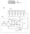
- Fig. 1 is an illustration of one embodiment of a fuel system 102 of an engine.
- the fuel system 102 includes at least one hydraulically-actuated electronically-controlled injector (HEUI) 104 for each combustion chamber or cylinder (not shown) of the fuel system 102.
- the fuel system 102 also includes a circuit 122 for supplying actuating fluid to each injector 104.
- the circuit 122 includes a pump 106, driven by an internal combustion engine 108.
- the output of the pump 106 is connected to each fuel injector 104 and also to a fluid sump (or tank) 110.
- the fluid sump 110 is also attached, through a return line, back to the pump 106.
- Each injector 104 is also connected to the fluid sump 110 in order to return the actuating fluid to the sump 110.
- the circuit 122 includes a pressure sensor 116.
- the pressure sensor 116 is located between a pressure control valve 112, and the injectors 104.
- the pressure sensor 116 senses the pressure of the actuating fluid and responsively generates a pressure signal.
- a means for determining the fluid flow is included in the circuit 122.
- a flow sensor 118 located at the output of the pump 106, may be used to determine the flow of the fluid, and responsively generate a fluid flow signal.
- an engine speed sensor (not shown) may be used to sense the speed of the engine 108, and responsively generate a flow signal based on the sensed engine speed.
- the pump 106 is a fixed displacement pump. Therefore, the flow may be determined by multiplying the engine speed by the pump displacement per revolutions per minute of the engine speed.
- a variable displacement pump may be used if the pump is stroked to a known displacement, such as either minimum or maximum stroke, during engine cranking.
- the circuit 122 includes a temperature sensor 124.
- the temperature sensor 124 senses the temperature of the actuating fluid, and responsively generates a fluid temperature signal.
- the actuating fluid is petroleum based oil.
- the fluid may be a synthetic oil, fuel, or other type of non-compressible fluid.
- the circuit 122 includes an electronic controller 126.
- the controller 126 receives the pressure signal, the temperature signal, and the flow signal, and responsively determines a viscosity range of the actuating fluid.
- the circuit 122 includes a pressure control valve 112 for regulating how much actuating fluid flows to the injectors 104 as opposed to the fluid sump 110. By adjusting how much of the actuating fluid flow provided by the pump 106 goes to the injectors 104 as compared to the sump 110, the pressure of the fluid supplied to the injectors 104 may be regulated.
- the pressure sensor 116 senses the pressure of the fluid flowing to the injectors 104 and provides feedback to an electronic controller 126.
- the electronic controller 126 compares a desired pressure to an actual pressure to form a closed loop system for maintaining pressure. For example, if the sensed fluid pressure exceeds the desired pressure the electronic controller 126 commands the pressure control valve 112 through an electronic signal, to increase the amount of fluid flow to the sump 110 thereby bringing the injector pressure down to the desired level.
- the present invention includes a method for determining a viscosity range of an actuating fluid located within a fuel system 122.
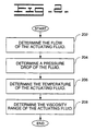
- the method includes the steps of determining a flow, temperature, and pressure drop of the actuating fluid, and responsively determining a viscosity range of the actuating fluid.
- Fig. 2 illustrates a flow diagram of the method of the present invention.
- the flow of the actuating fluid is determined.
- the fluid flow may be determined by sensing the speed of the pump 106 and multiplying the speed by the pump displacement.
- the speed of the pump 106 may be determined by sensing the speed of the internal combustion engine 108 driving the pump 106.
- a second control block 204 the pressure of the fluid is sensed by the pressure sensor 116, and a pressure signal is delivered to the electronic controller 126.
- the pressure is sensed in order to determine a pressure drop of the actuating fluid across a consistent orifice within the circuit 122.
- the term consistent in this context means that the area of the orifice is fixed for a given condition, e.g., whenever the same condition occurs, the area of the orifice will be the same.
- the pressure is determined during cranking of the engine, and the pressure drop is measured across the pressure control valve 112. During the cranking of the engine, the solenoids associated with the fuel injectors, are not activated.
- the injectors 104 do not fire, and the actuating fluid does not flow through the injectors 104, al beit leakage.
- the fluid is circulated from the pump 106, through the pressure control valve 112, to the fluid sump 110, and back to the pump 106.
- no current is provided to the pressure control valve.
- the pressure control valve is used as a consistent orifice which a pressure drop may be measured across.
- the pressure drop may be measured across the pressure control valve 112.
- the pressure drop may be determined by using a pressure sensor 116 located between the injectors 106 and the pressure control valve 112.
- the pressure on the low side of the pressure control valve 112, i.e., at the fluid sump 110, may be assumed to be at atmospheric levels, or measured by the internal combustion engine atmospheric pressure sensor if so equipped. Therefore the output of the pressure sensor 116 may be used to sense the amount of pressure drop across the pressure control valve 112.
- another pressure sensor (not shown) may be located between the pressure control valve 112 and the sump 110. Then the difference between the pressure reading of the pressure sensors located before and after the pressure control valve 112 will indicate the pressure drop across the pressure control valve 112.
- a third control block 206 the temperature of the fluid is sensed by the temperature sensor 124, and a temperature signal is delivered to the electronic controller 126.
- the viscosity range of the actuating fluid is determined.
- an actuating fluid is a petroleum based oil.
- the viscosity range of the actuating fluid may be defined as a function of the oil grade.
- Oil grade may be defined by the widely recognized SAE standard J300 "Engine oil Viscosity Classification.” This specification sets the allowable viscosity for a given oil grade, as illustrated in Table 1 below.
- SAE Viscosity Grade Low Temp(C) Cranking Viscosity (cP) Max Kinematic Viscosity (cSt) at 100C Min Kinematic Viscosity (cSt) at 100C Max 0W 3250 at -30C - - 5W 3500 at -25C - - 10W 3500 at -20C - - 15W 3500 at -15C - - 20W 4500 at -10C - - 25W 6000 at -5C - - 20 - 5.6 9.3 30 - 9.3 12.5 40 - 12.5 16.3 50 - 16.3 21.9 60 - 21.9 26.1
- Two series of viscosity grades are defined, those containing the letter W and those without the letter W.
- Single viscosity grade oils with the letter W are defined by maximum lower temperature viscosity.
- Single grade oils without the letter W are based on a set of minimum and maximum kinematic viscosities at 100C.
- Multi-viscosity grade oils (“multi-grades") are defined by both of the following criteria: maximum low temperature viscosity corresponding to one of the W grades and maximum and minimum viscosities at 100C corresponding to one of the non-W grades.
- the A and B values for the equation, bounding the upper viscosity range versus temperature for a given multi-grade oil are obtained by solving the equation using the maximum viscosity points defined at both 100C and the low temperature as specified in Table 1. From this an upper bound viscosity range for each multi-grade oil is defined per SAE J300.
- the viscosity of an actuating fluid is a function of the oil grade and temperature, as illustrated in Fig. 3.
- the oil grade as defined per SAE J300, indicates a maximum viscosity bound of a oil for a given temperature. Therefore, once the oil grade the fluid most closely resembles, i.e., representative of the fluid, is determined, a viscosity range may be determined.
- the actual viscosity of the actuating fluid may be determined to be within the viscosity range. Since the oil grade defines a maximum viscosity bound, the viscosity range may be determined to be between the oil grade identified, and the next lower oil grade viscosity bound.
- the viscosity range may be determined to be between 20,000 cP (15W40 @ -25C) and 10,000 cP (10W30 @ -25C).
- the controller 126 may either use the viscosity range, or select a viscosity within the range as the viscosity of the fluid.
- the viscosity of the fluid may be selected to be 15,000 cP, the mid point of the identified viscosity range.
- the viscosity range may be determined as a function of oil grade.
- the oil grade which the actuating fluid most closely resembles in terms of viscosity may be determined in response to the flow, temperature, and pressure drop of the actuating fluid.
- a map of a particular oil grade may be predetermined as a function of the fluid flow, pressure drop, and temperature of the fluid through empirical analysis, simulation and testing, as illustrated in Fig. 4.
- the fluid temperature may be set, then the fluid flow may be varied, and the pressure drop across a consistent orifice may be measured.
- the shape of the oil grade map for a given oil grade is based on the relationship of the magnitude of a pressure drop across a consistent orifice for a given flow being directly proportional to the viscosity of the fluid.
- Oil grade maps of all the potential oil grades that may be used in the fuel system may be determined in a similar manner, as illustrated in Fig. 5.
- the controller 126 receives the sensed flow, pressure drop, and temperature signals.
- the flow, pressure, and temperature are used to determine the oil grade most closely resembling the viscosity characteristics of the actuating fluid.
- the oil grade map closest to the measured parameters indicates the oil grade the actuating fluid most closely resembles.
- the oil grade map may be implemented as a multi-variable look up table, providing oil grade as a function of the temperature, pressure drop and flow of the actuating fluid.
- the viscosity range may be determined as described above. Therefore, the viscosity range may be determined based on the flow, temperature, and pressure drop of the actuating fluid.
- the oil grade most closely resembling the characteristics of the actuating fluid, or the viscosity range may then be used to determine and control operational characteristics of the fuel system, including the desired fuel quantity, desired pressure of the actuating fluid, desired injection electrical duration, start of fuel delivery, and desired injection timing.
- the viscosity range is determined during cranking, in part because the pressure control valve provides a consistent orifice which a pressure drop may be measured across.
- the viscosity range may be continuously determined during the operation of the fuel system 102.
- Fig. 6 illustrates an alternative configuration of a fuel system 602, having a fixed geometry orifice 606 located between the fuel injectors 104 and the fluid sump 110.
- the fixed geometry orifice 606 provides a consistent orifice which a pressure drop may be measured across.
- a flow sensor 604 may be located near the consistent orifice 606 to measure the fluid flow through the orifice.
- the pressure, temperature, and flow of the actuating fluid may be continuously monitored, and the oil grade and viscosity range of the fluid may be continuously determined.
- One advantage of this method is that, as the temperature, or other characteristics of the fluid change over the operation of the fuel system 602, the viscosity range of the fluid may be continuously updated to ensure changes in the fluid viscosity may be accounted for when determining the operational characteristics of the fuel system 602.
- the controller 126 may then deliver the viscosity information, such as the viscosity range, or oil grade the fluid most closely resembles, to other internal or external programs that use the information for fuel system control strategies.
- the fuel injector on-time or a solenoid duration enables actuating fluid to flow to the injectors may be modified to ensure the proper amount of fuel is injected, and the desired injection timing is realized.
- the present invention provides a method and apparatus for determining a viscosity range of an actuating fluid in a hydraulic-electronic fuel system.
- the method includes the steps of determining a flow, pressure drop, and temperature of the actuating fluid, and responsively determining the viscosity range of the actuating fluid.
- the viscosity of the actuating fluid effects both when fuel is delivered (the injection timing) and amount of fuel delivered by the injector, as illustrated in Fig. 7A and 7B.
- the actuating fluid in cold temperatures the actuating fluid is thicker, i.e., has a higher viscosity (line 702, 704), than at warm temperatures (line 706, 708). Therefore, when an electrical signal is delivered to a solenoid controlling a fuel injector, commanding the solenoid to enable the delivery of actuating fluid to the injector at time t 0 710, the fluid flows at a slower rate.
- the actuating fluid flows into a chamber within the fuel injector and pushes down on a plunger enabling fuel to pass out the injector nozzle.
- the injectors are initially deenergized, preventing fuel from being injected.
- the actuating fluid is circulated from the pump 106, through a fluid pressure valve 114, a pressure control valve 112, a fluid sump 110, and back to the pump 106.
- the fluid flow, pressure, and temperature are sensed, and signals are respectively delivered to a controller 126.
- the actuating fluid is petroleum based oil.
- the controller 126 determines the viscosity range of the fluid based upon the fluid flow, temperature, and pressure drop of the fluid.
- the information may be delivered to a control strategy to determine and control the operational characteristics of the fuel system including the desired fuel quantity, desired injection duration, desired injection timing, and desired fluid pressure, thereby improving the overall performance of the fuel system.
- the injectors 104 are then enabled for firing via the electrical solenoids (not shown).
- the flow, temperature, and pressure of the actuating fluid are continuously monitored to continuously determine the viscosity range of the actuating fluid.
- One of the advantages of the present invention is that as the viscosity of the fluid changes, e.g., the fluid begins to change characteristics due to use over time, the present invention will continue to dynamically determine the viscosity of the fluid and to select the grade the fluid most closely resembles. Therefore overall system performance is not adversely affected if oil begins to break down, i.e., become less viscous over time, or the operating temperature of the engine changes.
Landscapes
- Engineering & Computer Science (AREA)
- Chemical & Material Sciences (AREA)
- Immunology (AREA)
- Pathology (AREA)
- Analytical Chemistry (AREA)
- Biochemistry (AREA)
- General Health & Medical Sciences (AREA)
- General Physics & Mathematics (AREA)
- Physics & Mathematics (AREA)
- Life Sciences & Earth Sciences (AREA)
- Health & Medical Sciences (AREA)
- Combustion & Propulsion (AREA)
- Mechanical Engineering (AREA)
- General Engineering & Computer Science (AREA)
- Fuel-Injection Apparatus (AREA)
- Combined Controls Of Internal Combustion Engines (AREA)
- Electrical Control Of Air Or Fuel Supplied To Internal-Combustion Engine (AREA)
Claims (13)
- Procédé de détermination d'un indice représentatif d'un fluide d'actionnement disposé dans un système de carburant (102) d'un moteur, comprenant les étapes suivantes :déterminer le débit du fluide d'actionnement ;déterminer la chute de pression du fluide d'actionnement au travers d'un orifice cohérent (112) disposé dans le système de carburant ;déterminer la température du fluide d'actionnement et ;déterminer l'indice du fluide d'actionnement en réponse auxdits débit, température et chute de pression.
- Procédé selon la revendication 1, comprenant en outre l'étape consistant à déterminer une plage de viscosité du fluide d'actionnement en réponse à la température et à l'indice.
- Procédé selon la revendication 1 ou 2, dans lequel le fluide d'actionnement est une huile de synthèse ou une huile naturelle.
- Procédé selon la revendication 1, dans lequel l'étape de détermination de l'indice comprend en outre l'étape de sélection d'un indice d'huile représentatif parmi une pluralité d'indices d'huile en réponse au débit, à la chute de pression et à la température du fluide d'actionnement.
- Procédé selon la revendication 4, comprenant en outre l'étape de détermination d'une plage de viscosité en réponse à l'indice d'huile représentatif.
- Procédé selon la revendication 1, dans lequel l'étape de détermination de l'indice comprend en outre les étapes suivantes :comparer la température, le débit et la chute de pression à une pluralité de tables d'indices d'huile ; etdéterminer l'indice d'huile en réponse à ladite comparaison.
- Procédé selon la revendication 6, dans lequel l'étape de détermination de débit comprend en outre les étapes suivantes :déterminer la vitesse d'un moteur de pompe ;déterminer le déplacement de la pompe ; etdéterminer le débit en réponse à la vitesse du moteur de pompe et au déplacement de la pompe.
- Procédé selon la revendication 1, dans lequel l'étape de détermination de la chute de pression comprend la détermination de la chute de pression du fluide d'actionnement au travers d'un orifice cohérent (112) du système de carburant pendant l'allumage du moteur.
- Dispositif pour déterminer une plage de viscosité d'un fluide d'actionnement disposé dans un système de carburant (102) d'un moteur comprenant :des moyens pour déterminer le débit du fluide d'actionnement et produire en réponse un signal de débit ;un capteur de pression (116) adapté à détecter la pression du fluide d'actionnement en travers d'un orifice cohérent (112) disposé dans le système de carburant et à produire en réponse un signal de pression ;un capteur de température (124) adapté à détecter la température du fluide d'actionnement et à produire en réponse un signal de température ; etun contrôleur (126) adapté à recevoir le signal de débit, le signal de pression et le signal de température et à déterminer en réponse la plage de viscosité du fluide d'actionnement.
- Dispositif selon la revendication 9, dans lequel la plage de viscosité est définie en fonction d'au moins un indice d'huile.
- Dispositif selon la revendication 9, dans lequel le contrôleur (126) détermine un indice d'huile représentatif du fluide en réponse au signal de débit, au signal de pression et au signal de température, et détermine la plage de viscosité en réponse à l'indice d'huile.
- Dispositif selon la revendication 11, dans lequel le contrôleur (126) comprend en outre une table ou un moyen de correspondance contenant au moins une table d'indices d'huile prédéterminés en fonction du débit, de la pression et de la température, l'indice d'huile étant déterminé en réponse à la table ou au moyen de correspondance.
- Dispositif selon la revendication 9, dans lequel l'orifice cohérent (112) est une soupape de commande de pression.
Applications Claiming Priority (3)
| Application Number | Priority Date | Filing Date | Title |
|---|---|---|---|
| US09/211,626 US6216528B1 (en) | 1998-12-15 | 1998-12-15 | Method and apparatus for determining a viscosity of an actuating fluid |
| PCT/US1999/028937 WO2000036394A1 (fr) | 1998-12-15 | 1999-12-07 | Procede et appareil de determination de la viscosite d'un fluide moteur |
| US211626 | 2002-08-02 |
Publications (2)
| Publication Number | Publication Date |
|---|---|
| EP1055109A1 EP1055109A1 (fr) | 2000-11-29 |
| EP1055109B1 true EP1055109B1 (fr) | 2004-08-25 |
Family
ID=22787708
Family Applications (1)
| Application Number | Title | Priority Date | Filing Date |
|---|---|---|---|
| EP99964133A Expired - Lifetime EP1055109B1 (fr) | 1998-12-15 | 1999-12-07 | Procede et appareil de determination de la viscosite d'un fluide moteur |
Country Status (5)
| Country | Link |
|---|---|
| US (1) | US6216528B1 (fr) |
| EP (1) | EP1055109B1 (fr) |
| JP (1) | JP2002532711A (fr) |
| DE (1) | DE69919680T2 (fr) |
| WO (1) | WO2000036394A1 (fr) |
Families Citing this family (24)
| Publication number | Priority date | Publication date | Assignee | Title |
|---|---|---|---|---|
| EP1029160B1 (fr) * | 1997-11-07 | 2003-04-09 | Volkswagen Aktiengesellschaft | Procede et dispositif pour surveiller et/ou determiner la qualite d'une huile de moteur |
| DE19915471A1 (de) * | 1999-04-06 | 2000-10-12 | Zahnradfabrik Friedrichshafen | Vorrichtung zur Messung der Getriebeöltemperatur |
| US6415652B1 (en) * | 1999-12-17 | 2002-07-09 | Caterpillar Inc. | Method and apparatus for determining an oil grade of an actuating fluid |
| US6840093B2 (en) | 2002-04-05 | 2005-01-11 | Caterpillar Inc. | System and method for determining oil grade |
| US6675635B2 (en) * | 2002-04-17 | 2004-01-13 | Caterpillar Inc | System and method for determining oil quality |
| US6695470B1 (en) | 2002-09-10 | 2004-02-24 | Delphi Technologies, Inc. | Apparatus and method for viscosity measurement |
| US7178491B2 (en) | 2003-06-05 | 2007-02-20 | Caterpillar Inc | Control system and method for engine valve actuator |
| US6836982B1 (en) | 2003-08-14 | 2005-01-04 | Caterpillar Inc | Tactile feedback system for a remotely controlled work machine |
| US7107828B2 (en) * | 2005-02-24 | 2006-09-19 | Daimlerchrysler Corporation | Method and code for controlling actuator responsive to oil pressure using oil viscosity measure |
| DE102006059071A1 (de) * | 2006-12-14 | 2008-06-19 | Robert Bosch Gmbh | Verfahren zur Bestimmung der Ölqualität |
| JP4966828B2 (ja) | 2007-11-15 | 2012-07-04 | ヤンマー株式会社 | 燃料供給装置及び燃料供給方法 |
| US8109138B2 (en) * | 2008-11-19 | 2012-02-07 | GM Global Technology Operations LLC | Method and system for estimating engine oil life based on viscosity |
| JP5212400B2 (ja) * | 2009-04-15 | 2013-06-19 | 株式会社デンソー | 圧力検出装置 |
| EP2564181B1 (fr) * | 2010-04-26 | 2021-08-25 | RheoSense, Inc. | Viscosimètre portable |
| US9303580B2 (en) * | 2012-10-26 | 2016-04-05 | Ford Global Technologies, Llc | Detection of diesel fuel gelling |
| US9341129B2 (en) | 2013-10-15 | 2016-05-17 | Ford Global Technologies, Llc | Viscosity detection using starter motor |
| US9523320B2 (en) | 2013-10-15 | 2016-12-20 | Ford Global Technologies, Llc | Viscosity detection using sump |
| CN106415236B (zh) | 2014-04-11 | 2021-04-20 | 电流感应器公司 | 粘度计和使用该粘度计的方法 |
| EP3043040B1 (fr) * | 2015-01-06 | 2017-12-20 | Inergy Automotive Systems Research (Société A.) | Système de stockage de liquide pour véhicule, véhicule comprenant ledit système et procédé d'évaluation de la qualité d'un liquide dans celui-ci |
| WO2017008027A1 (fr) * | 2015-07-09 | 2017-01-12 | Nordson Corporation | Système de transport et de distribution de matière alimentaire chauffée |
| DE102015223848A1 (de) * | 2015-12-01 | 2017-06-01 | Robert Bosch Gmbh | Verfahren zum Ermitteln einer Viskosität eines Kraftstoffs |
| US20190128157A1 (en) | 2017-11-02 | 2019-05-02 | Exxonmobil Research And Engineering Company | Selection of engine maps based on in-situ detection of viscosity |
| US10968795B2 (en) * | 2019-04-09 | 2021-04-06 | Ford Global Technologies, Llc | Methods and systems for detection of particles in lubricant |
| CN117677414A (zh) | 2021-05-10 | 2024-03-08 | 电流感应器公司 | 具有减小的死体积和高动态范围的粘度计 |
Family Cites Families (7)
| Publication number | Priority date | Publication date | Assignee | Title |
|---|---|---|---|---|
| US5181494A (en) | 1991-10-11 | 1993-01-26 | Caterpillar, Inc. | Hydraulically-actuated electronically-controlled unit injector having stroke-controlled piston and methods of operation |
| US5357912A (en) | 1993-02-26 | 1994-10-25 | Caterpillar Inc. | Electronic control system and method for a hydraulically-actuated fuel injection system |
| US5564391A (en) | 1993-06-16 | 1996-10-15 | Caterpillar Inc. | Electronic control for a hydraulic-actuator unit injector fuel system and method for operating same |
| US5423302A (en) | 1994-03-23 | 1995-06-13 | Caterpillar Inc. | Fuel injection control system having actuating fluid viscosity feedback |
| US5634448A (en) | 1994-05-31 | 1997-06-03 | Caterpillar Inc. | Method and structure for controlling an apparatus, such as a fuel injector, using electronic trimming |
| JPH1089090A (ja) * | 1996-09-19 | 1998-04-07 | Isuzu Motors Ltd | 油圧作動式電子制御燃料噴射装置並びに油粘度測定装置及び油粘度測定方法 |
| US5750887A (en) | 1996-11-18 | 1998-05-12 | Caterpillar Inc. | Method for determining a remaining life of engine oil |
-
1998
- 1998-12-15 US US09/211,626 patent/US6216528B1/en not_active Expired - Lifetime
-
1999
- 1999-12-07 EP EP99964133A patent/EP1055109B1/fr not_active Expired - Lifetime
- 1999-12-07 JP JP2000588586A patent/JP2002532711A/ja not_active Withdrawn
- 1999-12-07 DE DE69919680T patent/DE69919680T2/de not_active Expired - Fee Related
- 1999-12-07 WO PCT/US1999/028937 patent/WO2000036394A1/fr not_active Ceased
Also Published As
| Publication number | Publication date |
|---|---|
| EP1055109A1 (fr) | 2000-11-29 |
| DE69919680T2 (de) | 2005-09-22 |
| US6216528B1 (en) | 2001-04-17 |
| JP2002532711A (ja) | 2002-10-02 |
| DE69919680D1 (de) | 2004-09-30 |
| WO2000036394A1 (fr) | 2000-06-22 |
Similar Documents
| Publication | Publication Date | Title |
|---|---|---|
| EP1055109B1 (fr) | Procede et appareil de determination de la viscosite d'un fluide moteur | |
| US5630383A (en) | Lubricating oil supplying system for engine | |
| US5423302A (en) | Fuel injection control system having actuating fluid viscosity feedback | |
| US6467452B1 (en) | Method and apparatus for delivering multiple fuel injections to the cylinder of an internal combustion engine | |
| US5485820A (en) | Injection control pressure strategy | |
| US6879903B2 (en) | Method for estimating fuel injector performance | |
| US6152107A (en) | Device for controlling fuel injection in cold engine temperatures | |
| US5893347A (en) | Method for delivering a small quantity of fuel with a hydraulically-actuated injector during split injection | |
| US6480781B1 (en) | Method and apparatus for trimming an internal combustion engine | |
| WO2002006657A9 (fr) | Procede et appareil servant a alimenter par injections multiples de carburant le cylindre d'un moteur thermique | |
| US6840093B2 (en) | System and method for determining oil grade | |
| US6102005A (en) | Adaptive control for power growth in an engine equipped with a hydraulically-actuated electronically-controlled fuel injection system | |
| US5901682A (en) | Method for transitioning between different operating modes of an internal combustion engine | |
| US6192868B1 (en) | Apparatus and method for a cold start timing sweep | |
| US5690065A (en) | Method and device for optimizing air filling in an internal combustion engine cylinder | |
| US6415762B1 (en) | Accurate deliver of total fuel when two injection events are closely coupled | |
| US6508107B2 (en) | Method and apparatus for determining an oil grade of an actuating fluid | |
| US6305358B1 (en) | Method and apparatus for dynamic trimming of fuel system | |
| US6237572B1 (en) | Apparatus and method for determining start of injection of a fuel injector | |
| GB2256945A (en) | An idling r.p.m. control system for a two-stroke engine | |
| US6360717B1 (en) | Fuel injection system and a method for operating | |
| JPH0849629A (ja) | エンジンのタイミング制御タペット装置 | |
| EP0543423B1 (fr) | Système de prélèvement de l'huile de lubrification pour un moteur à combustion interne | |
| CN1995730B (zh) | 用于控制多次燃油喷射的供给量的系统 | |
| US20070199545A1 (en) | Fuel system having variable waveform based on operator objective |
Legal Events
| Date | Code | Title | Description |
|---|---|---|---|
| PUAI | Public reference made under article 153(3) epc to a published international application that has entered the european phase |
Free format text: ORIGINAL CODE: 0009012 |
|
| AK | Designated contracting states |
Kind code of ref document: A1 Designated state(s): DE FR GB |
|
| 17P | Request for examination filed |
Effective date: 20001222 |
|
| 17Q | First examination report despatched |
Effective date: 20011025 |
|
| GRAP | Despatch of communication of intention to grant a patent |
Free format text: ORIGINAL CODE: EPIDOSNIGR1 |
|
| GRAS | Grant fee paid |
Free format text: ORIGINAL CODE: EPIDOSNIGR3 |
|
| GRAA | (expected) grant |
Free format text: ORIGINAL CODE: 0009210 |
|
| AK | Designated contracting states |
Kind code of ref document: B1 Designated state(s): DE FR GB |
|
| PG25 | Lapsed in a contracting state [announced via postgrant information from national office to epo] |
Ref country code: FR Free format text: LAPSE BECAUSE OF FAILURE TO SUBMIT A TRANSLATION OF THE DESCRIPTION OR TO PAY THE FEE WITHIN THE PRESCRIBED TIME-LIMIT Effective date: 20040825 |
|
| REG | Reference to a national code |
Ref country code: GB Ref legal event code: FG4D |
|
| REF | Corresponds to: |
Ref document number: 69919680 Country of ref document: DE Date of ref document: 20040930 Kind code of ref document: P |
|
| PG25 | Lapsed in a contracting state [announced via postgrant information from national office to epo] |
Ref country code: GB Free format text: LAPSE BECAUSE OF NON-PAYMENT OF DUE FEES Effective date: 20041207 |
|
| PLBE | No opposition filed within time limit |
Free format text: ORIGINAL CODE: 0009261 |
|
| STAA | Information on the status of an ep patent application or granted ep patent |
Free format text: STATUS: NO OPPOSITION FILED WITHIN TIME LIMIT |
|
| GBPC | Gb: european patent ceased through non-payment of renewal fee |
Effective date: 20041207 |
|
| 26N | No opposition filed |
Effective date: 20050526 |
|
| EN | Fr: translation not filed | ||
| PGFP | Annual fee paid to national office [announced via postgrant information from national office to epo] |
Ref country code: DE Payment date: 20081230 Year of fee payment: 10 |
|
| PG25 | Lapsed in a contracting state [announced via postgrant information from national office to epo] |
Ref country code: DE Free format text: LAPSE BECAUSE OF NON-PAYMENT OF DUE FEES Effective date: 20100701 |