EP1055392A2 - Procédé de compensation de température dans un capteur combinant pression et température - Google Patents
Procédé de compensation de température dans un capteur combinant pression et température Download PDFInfo
- Publication number
- EP1055392A2 EP1055392A2 EP00850088A EP00850088A EP1055392A2 EP 1055392 A2 EP1055392 A2 EP 1055392A2 EP 00850088 A EP00850088 A EP 00850088A EP 00850088 A EP00850088 A EP 00850088A EP 1055392 A2 EP1055392 A2 EP 1055392A2
- Authority
- EP
- European Patent Office
- Prior art keywords
- excitation
- signal
- sensor
- temperature
- coupled
- Prior art date
- Legal status (The legal status is an assumption and is not a legal conclusion. Google has not performed a legal analysis and makes no representation as to the accuracy of the status listed.)
- Granted
Links
Images


Classifications
-
- A—HUMAN NECESSITIES
- A61—MEDICAL OR VETERINARY SCIENCE; HYGIENE
- A61B—DIAGNOSIS; SURGERY; IDENTIFICATION
- A61B5/00—Measuring for diagnostic purposes; Identification of persons
- A61B5/02—Detecting, measuring or recording for evaluating the cardiovascular system, e.g. pulse, heart rate, blood pressure or blood flow
- A61B5/021—Measuring pressure in heart or blood vessels
- A61B5/0215—Measuring pressure in heart or blood vessels by means inserted into the body
- A61B5/02156—Calibration means
-
- A—HUMAN NECESSITIES
- A61—MEDICAL OR VETERINARY SCIENCE; HYGIENE
- A61B—DIAGNOSIS; SURGERY; IDENTIFICATION
- A61B5/00—Measuring for diagnostic purposes; Identification of persons
- A61B5/01—Measuring temperature of body parts ; Diagnostic temperature sensing, e.g. for malignant or inflamed tissue
-
- A—HUMAN NECESSITIES
- A61—MEDICAL OR VETERINARY SCIENCE; HYGIENE
- A61B—DIAGNOSIS; SURGERY; IDENTIFICATION
- A61B5/00—Measuring for diagnostic purposes; Identification of persons
- A61B5/68—Arrangements of detecting, measuring or recording means, e.g. sensors, in relation to patient
- A61B5/6846—Arrangements of detecting, measuring or recording means, e.g. sensors, in relation to patient specially adapted to be brought in contact with an internal body part, i.e. invasive
- A61B5/6847—Arrangements of detecting, measuring or recording means, e.g. sensors, in relation to patient specially adapted to be brought in contact with an internal body part, i.e. invasive mounted on an invasive device
- A61B5/6851—Guide wires
-
- G—PHYSICS
- G01—MEASURING; TESTING
- G01L—MEASURING FORCE, STRESS, TORQUE, WORK, MECHANICAL POWER, MECHANICAL EFFICIENCY, OR FLUID PRESSURE
- G01L19/00—Details of, or accessories for, apparatus for measuring steady or quasi-steady pressure of a fluent medium insofar as such details or accessories are not special to particular types of pressure gauges
- G01L19/06—Means for preventing overload or deleterious influence of the measured medium on the measuring device or vice versa
- G01L19/0627—Protection against aggressive medium in general
-
- G—PHYSICS
- G01—MEASURING; TESTING
- G01L—MEASURING FORCE, STRESS, TORQUE, WORK, MECHANICAL POWER, MECHANICAL EFFICIENCY, OR FLUID PRESSURE
- G01L19/00—Details of, or accessories for, apparatus for measuring steady or quasi-steady pressure of a fluent medium insofar as such details or accessories are not special to particular types of pressure gauges
- G01L19/14—Housings
- G01L19/149—Housings of immersion sensor, e.g. where the sensor is immersed in the measuring medium or for in vivo measurements, e.g. by using catheter tips
-
- G—PHYSICS
- G01—MEASURING; TESTING
- G01L—MEASURING FORCE, STRESS, TORQUE, WORK, MECHANICAL POWER, MECHANICAL EFFICIENCY, OR FLUID PRESSURE
- G01L9/00—Measuring steady of quasi-steady pressure of fluid or fluent solid material by electric or magnetic pressure-sensitive elements; Transmitting or indicating the displacement of mechanical pressure-sensitive elements, used to measure the steady or quasi-steady pressure of a fluid or fluent solid material, by electric or magnetic means
- G01L9/02—Measuring steady of quasi-steady pressure of fluid or fluent solid material by electric or magnetic pressure-sensitive elements; Transmitting or indicating the displacement of mechanical pressure-sensitive elements, used to measure the steady or quasi-steady pressure of a fluid or fluent solid material, by electric or magnetic means by making use of variations in ohmic resistance, e.g. of potentiometers, electric circuits therefor, e.g. bridges, amplifiers or signal conditioning
- G01L9/06—Measuring steady of quasi-steady pressure of fluid or fluent solid material by electric or magnetic pressure-sensitive elements; Transmitting or indicating the displacement of mechanical pressure-sensitive elements, used to measure the steady or quasi-steady pressure of a fluid or fluent solid material, by electric or magnetic means by making use of variations in ohmic resistance, e.g. of potentiometers, electric circuits therefor, e.g. bridges, amplifiers or signal conditioning of piezo-resistive devices
- G01L9/065—Measuring steady of quasi-steady pressure of fluid or fluent solid material by electric or magnetic pressure-sensitive elements; Transmitting or indicating the displacement of mechanical pressure-sensitive elements, used to measure the steady or quasi-steady pressure of a fluid or fluent solid material, by electric or magnetic means by making use of variations in ohmic resistance, e.g. of potentiometers, electric circuits therefor, e.g. bridges, amplifiers or signal conditioning of piezo-resistive devices with temperature compensating means
Definitions
- the present invention relates generally to a method of determining the pressure, temperature and optionally flow in the medical area, especially to in situ measurement of the intracoronary pressure, distally of a stricture using a guide wire having a pressure sensor at its distal end.
- the measurement of the distal pressure is made in the vessel using a micro-pressure transducer, and the proximal pressure is the arterial pressure.
- a sensor for temperature and pressure measurements having a pressure sensitive resistor (referred to as an active resistor) and a temperature sensitive resistor (referred to as a passive resistor). These resistors are part of a Wheatstone bridge comprising a total of four resistors and three "parasitic" cable resistances. Two different measurements are performed in this bridge, namely a measurement of a differential output voltage (potential difference between the Active and Passive circuit) which is used for pressure measurement and single ended output voltage (voltage across the Passive circuit), which is used for temperature measurement. Only the passive and the active resistor are located on the actual sensor chip that is inserted into the body.
- the remaining resistors in the bridge are located externally, suitably in the control unit, and are coupled to the chip via electrical leads running inside a guide wire on the distal end of which the chip is located.
- This system functions appropriately when the environment is such that the properties of the electrical leads are not affected.
- the resistance of the leads could vary considerably if the fraction of the length of the leads that are exposed to the body temperature varies, namely, if the guide wire need to be manipulated over distances of more than a few centimetres. This effect is obtained in general when the temperature surrounding the guide wire changes e.g. when flushing with saline having a temperature differing the from body temperature.
- the object of the invention is therefore to provide a measurement method using a single unit having as few electrical leads as possible, namely only three, and allowing compensation for variations in resistance of the leads coupling the resistors in the sensor to the control unit, in order to obtain a reliable measurement.
- the object outlined above is achieved according to the invention with the method of measurement defined in claim 1.
- the method comprises the excitation of the sensors so as to produce two distinguishable signals. At least a component of at least one of the signals is representative of the cable resistance and can be used for compensation purposes.
- an apparatus suitable for such measurements having temperature compensation means.
- the compensation means comprises circuitry for selectively and independently registering a resistance value for the passive resistor on the chip.
- the apparatus is defined in claim 12.
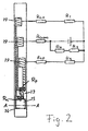
- FIG. 1a A distal portion of a sensor and guide wire assembly as disclosed in WO 97/27802, is shown in Fig. 1a.
- the device comprises a solid wire 1 inserted into a proximal tube portion 2.
- the wire 1 forms the distal portion of the guide wire and is extended beyond the distal end of the proximal tube 2 where the tube is connected to, or provided with an integrally formed, spiral portion 3
- a pressure sensor 6 is mounted at the distal end of the wire 1.
- electrical leads from the electrical circuitry run parallel with the wire 1.
- the sensor 6 is protected by a short section of a tube 7 having an aperture 8 through which a surrounding medium acts on the pressure sensor.
- a radio opaque coil 9 made of Pt and used for location purpose.
- a safety wire 10 for securing the distal part or the spiral 9.
- the proximal tube 2 and the spiral portion 3 may be connected in such a way that they can be used as electrical shield.
- a catheter tip pressure transducer which can be used with th present invention.
- This system comprises a catheter 20 closed by an end member 22.
- This member also functions as a support for a sensor 24 having a pressure sensitive diaphragm 26.
- Electrical leads 28 couple the sensor to external equipment.
- the sensor may be protected by a material such as silicon rubber 30.
- Pressure sensing resistor R a (a for "active") and temperature sensing resistor R p (p for “passive") are located on the actual sensor chip, and are coupled to the measurement device using insulated cables having resistances R ca, R cp and R ccom, these cables are mounted inside said proximal tube. These cables couples resistors R a , R p into the measurement device, and together with internal resistors R 1 and R 2 they form a Wheatstone bridge. This Wheatstone bridge is driven by the excitation voltage V DCEx , and the differential output voltage V (a-p) from the bridge is read using an instrumentation amplifier. Single ended output voltage V p in the temperature sensing circuit is read by an other instrumentation amplifier.
- Amplifier output signals V (a-p) and V p are coupled into the multiplexer, the amplifier outputs V (a-p) and V p being sequentially switched into an A/D convener for conversion into digital data.
- This data is read from A/D convener using a microcontroller CPU or digital signal processor DSP.
- CPU/DSP performs calculations needed to obtain the final pressure or temperature signal, and finally the measured values are presented on a numerical display.
- R a and R p are the resistances of the active sensor element and the resistance of the passive element respectively, as previously described. Their resistance may vary differently with the temperature i.e. TC Ra ⁇ TC Rp . Therefore a compensation of the pressure signal has to be made to compensate for the error related to varying temperature, i.e. it is known from the calibration curve which is achieved during manufacturing process how much has to be added to or subtracted from the registered pressure signal in order to get a correct pressure value.
- the circuit disclosed in Fig. 3 is supplied with excitation voltage or current (DC or AC).
- excitation voltage or current DC or AC
- most systems of the type the present invention is concerned with are operated with excitation voltages of up to 15 V.
- the differential voltage the active and the passive circuits V (a-p) is a representative signal for the measured pressure
- single ended voltage V p is a representative signal for the measured temperature. Because of the fact that the resistors R a and R p are not identical in terms of their temperature dependence, the differential voltage V (a-p) will be temperature dependent, therefore the pressure signal V (a-p) has to be compensated against varying temperature.
- every sensor is characterised in terms of temperature dependence and the calibration parameter is achieved by measuring simultaneously the temperature coefficient TC Rp of the passive element and the difference between TC Rp and temperature coefficient TC Ra of the active sensing element, this is done during manufacturing process.
- the result is thus a compensation factor which is used to compensate the sensor signal for temperature variations
- This factor which is unique to each individual sensor, is preferably stored in a PROM or the like, attached to the assembly of which the sensor forms a part.
- the compensated sensor signal is then equal to V a-p - T Factor *V p where, V a-p and V p are the measured potential difference between the active and the passive circuit, and the measured potential drop across the passive circuit, respectively (see Fig. 3)
- the prior art measurement method will function satisfactorily provided that the signal produced by change in the resistances of the cable, i. e. R Ca , R Ca and R Ccom due to the temperature, is negligible compared to the measured temperature signal.
- the resistance per unit length becomes high, which results in substantial total resistance of the cable.
- the temperature coefficient of copper is ⁇ 0.00433 °C -1 , which results in an increase of resistance in the cable by 0.173 ohm/°C.
- the resistance of the named resistor is typically ⁇ 3000 ohm, which results in the desired temperature signal of 0.9 ohm/°C.
- the relationship between undesired change in the cable resistance and desired temperature signal can now be calculated as 0.52 / 0.9 ⁇ 60 %, which means that 37 % of the temperature signal can actually originate from the change in cable temperature.
- This fact is crucial especially when the sensor is used for the temperature measurements, the temperature compensation of the pressure measurements are also influenced. Namely, there are applications where the cable length, which is exposed to the temperature change during the measurement is almost impossible to predict prior to the measurement procedure.
- the parts of the cable that will undergo a resistance change are those that are present in the same environment as the active sensor element (i.e. exposed to body temperature, higher than ambient). The contribution to the signal from the change of the cable resistances will thus be dependent on that length. In case the length affected by the temperature change is large, the contribution will also be large. Thus, a compensation for the change of the cable resistance is necessary.
- Switch SW 1 is coupled between V DCEx and R 2 in order to cut the excitation voltage to the passive circuit. If a measurement is now carried out with SW 1 open, and if one assumes that sum of R p and R Cp is negligible compared to the input impedance of the amplifiers that measures the voltages V p and V a-p , V p will then be a measure of potential drops across R Ccom (no current is flowing in the passive circuit), i.e. the contribution to the measured temperature signal from the change of the cable resistances due to the temperature. Now that the contribution to the temperature signal from the change of the cable resistances is determined it is possible to obtain the compensated temperature signal. It is given by V p - 3* V Popen where, 3*V P open is the compensation for the change of the cable resistances and V Popen is the voltage measured across the passive circuit with SW 1 open.
- SW 1 When SW 1 is closed the active element of the sensor yields a signal representative of the pressure, and its value is given by the signal V a-p .
- the switch SW 1 is operable at a selected frequency, the magnitude of which is dependent on other system parameters, and could vary within wide limits.
- Another way of obtaining a compensation for the cable resistance is to create two different modes of excitation using two different excitation voltages separated from each other in frequency.
- a schematic illustration is shown in Fig. 5.
- the Wheatstone bridge is driven by the excitation voltage V ACEx which is common to Active and Passive circuit.
- V ACEx which is common to Active and Passive circuit.
- a second excitation mode implemented, in this example a DC-voltage. It could of course be an AC voltage of a different frequency or phase.
- This additional DC excitation is applied in the Active circuit.
- V (a-p)AC the AC-component of the differential voltage V (a-p)AC in Fig. 5
- V pAC the AC-component of the single ended voltage
- V pDC DC-component of the single ended voltage V p in Fig. 5
- V pDC DC-component of the single ended voltage V p in Fig. 5
- the AC-component of the differential voltage V (a-p) is obtained by high-pass filtering the signal before entering into the amplifier.
- the output from this amplifier is then fed into the multiplexer and further to the A/D converter where the signal is converted into the digital code.
- This digital code is read by CPU/DSP which also calculates e.g. the RMS (root mean square) value of the pressure signal
- the AC-component of the single ended voltage V p is obtained by high-pass filtering the signal before entering into the amplifier.
- the output from this amplifier is then fed into the multiplexer and further to the A/D converter where the signal is converted into the digital code.
- This digital code is read by CPU/DSP which also calculates e.g. the RMS (root mean square) value of the temperature signal
- An additional amplifier is introduced to obtain the DC-component of the single ended voltage V p which is also low-pass filtered before entering said amplifier.
- the output from this amplifier is then fed into the multiplexer and further to the A/D converter where the signal is converted into the digital code, this digital code is read by CPU/DSP.
- the control unit shown in Fig. 7 comprises a first and a second instrumental amplifier having inputs for receiving said temperature signal respectively, and outputs delivering a processable out-signal. It comprises a multiplexer coupled to the outputs of said amplifiers, an A/D converter coupled to said multiplexer, and a control unit coupled to sequentially receive outputs from said A/D converter.
- excitation means comprising a DC voltage source and an AC voltage source, whereby the DC and AC excitation voltages are superimposed on each other.
- the control unit further comprises high pass filter means coupled to the input of said first instrumental amplifier, said input being coupled so as to receive a high frequency component of said pressure signal.
- the second instrumental amplifier also has a low pass filter means coupled to its input, said input being coupled so as to receive a low frequency component of said temperature signal.
- the third instrumental amplifier has a high pass filter means coupled to its input, said input being coupled so as to receive a high frequency component of said temperature signal and outputs delivering a processable out-signal.
- the Wheatstone bridge is driven by two D/A converters controlled from the CPU/DSP unit.
- a reference voltage source which is used for the setting of the full scale output from the D/A converters.
- This reference is also fed into the voltage divider network containing resistors R 3 and R 4 , the middle point voltage from this divider is used as reference level for the input amplifiers measuring V aAC and V pAC , this makes it possible to use higher gain without saturating these amplifiers.
- Two excitation modes can now be produced by supplying D/A converters with samples of data i.e. D/A converter supplying the circuit containing R 1 R ca and R a is fed with samples containing the waveform used as common excitation superimposed to the DC level used as second excitation mode, the D/A converter supplying the circuit containing R 2 R Cp and R p is fed with samples containing only the waveform used as the common excitation.
- V aAC the AC-component of the single ended voltage
- V pAC the AC-component of the single ended voltage
- V pDC the DC-component of the single ended voltage V p in Fig. 7 referred to as V pDC , which is proportional to the resistance in the common cable R Ccom .
- the AC-component of the single ended voltage V a is obtained by high-pass filtering the signal before feeding it into the amplifier.
- the output from this amplifier is then fed into the multiplexer and further to the A/D converter where the signal is converted into the digital data.
- This digital data is read by CPU/DSP which also calculates e.g. the RMS (root mean square) value of the signal.
- the AC-component of the single ended voltage V p is obtained by high-pass filtering the signal before entering into the amplifier.
- the output from this amplifier is then fed into the multiplexer and further to the A/D converter where the signal is converted into the digital data.
- This digital data is read by CPU/DSP which also calculates e.g. the RMS (root mean square) value of the temperature signal.
- An additional amplifier is introduced to obtain the DC-component of the single ended voltage V p which is also low-pass filtered before entering said amplifier.
- the output from this amplifier is then fed into the multiplexer and further to the A/D converter where the signal is converted into the digital data, this digital data is read by CPU/DSP.
Landscapes
- Health & Medical Sciences (AREA)
- Life Sciences & Earth Sciences (AREA)
- Physics & Mathematics (AREA)
- Molecular Biology (AREA)
- Animal Behavior & Ethology (AREA)
- General Physics & Mathematics (AREA)
- Biophysics (AREA)
- Pathology (AREA)
- Engineering & Computer Science (AREA)
- Biomedical Technology (AREA)
- Heart & Thoracic Surgery (AREA)
- Medical Informatics (AREA)
- Veterinary Medicine (AREA)
- Surgery (AREA)
- Public Health (AREA)
- General Health & Medical Sciences (AREA)
- Cardiology (AREA)
- Physiology (AREA)
- Vascular Medicine (AREA)
- Chemical & Material Sciences (AREA)
- Analytical Chemistry (AREA)
- Optics & Photonics (AREA)
- Measuring Fluid Pressure (AREA)
- Measuring Pulse, Heart Rate, Blood Pressure Or Blood Flow (AREA)
- Measuring And Recording Apparatus For Diagnosis (AREA)
Applications Claiming Priority (4)
| Application Number | Priority Date | Filing Date | Title |
|---|---|---|---|
| US13640199P | 1999-05-27 | 1999-05-27 | |
| SE9901962A SE9901962D0 (sv) | 1999-05-27 | 1999-05-27 | Improved method for temperature compensation in a sensor and guide wire assembly |
| SE9901962 | 1999-05-27 | ||
| US136401P | 1999-05-27 |
Publications (3)
| Publication Number | Publication Date |
|---|---|
| EP1055392A2 true EP1055392A2 (fr) | 2000-11-29 |
| EP1055392A3 EP1055392A3 (fr) | 2002-07-24 |
| EP1055392B1 EP1055392B1 (fr) | 2008-03-19 |
Family
ID=26663585
Family Applications (1)
| Application Number | Title | Priority Date | Filing Date |
|---|---|---|---|
| EP00850088A Expired - Lifetime EP1055392B1 (fr) | 1999-05-27 | 2000-05-18 | Procédé de compensation de température dans un capteur combinant pression et température |
Country Status (4)
| Country | Link |
|---|---|
| EP (1) | EP1055392B1 (fr) |
| JP (1) | JP3692014B2 (fr) |
| AT (1) | ATE389353T1 (fr) |
| DE (1) | DE60038332T2 (fr) |
Cited By (5)
| Publication number | Priority date | Publication date | Assignee | Title |
|---|---|---|---|---|
| EP1266610A3 (fr) * | 2001-06-15 | 2004-01-02 | Biosense, Inc. | Procédé et système de mesure de température et d'ajustement de la sensibilité à la température dans un dispositif médical ayant un senseur de position |
| US6992477B2 (en) | 2001-06-15 | 2006-01-31 | Biosense, Inc. | Medical device with position sensor having core with high permeability material for determining location coordinates of a portion of the medical device |
| RU2300739C2 (ru) * | 2005-08-09 | 2007-06-10 | Государственное образовательное учреждение высшего профессионального образования "Ульяновский государственный технический университет" | Способ компенсации аддитивной температурной погрешности датчика с вибрирующим элементом |
| RU2306530C2 (ru) * | 2005-08-09 | 2007-09-20 | Государственное образовательное учреждение высшего профессионального образования "Ульяновский государственный технический университет" | Способ компенсации аддитивной температурной погрешности датчика с вибрирующим элементом |
| WO2012062797A1 (fr) * | 2010-11-12 | 2012-05-18 | St Jude Medical Systems Ab | Unité d'interface, système de mesure et procédé dans une unité d'interface |
Families Citing this family (6)
| Publication number | Priority date | Publication date | Assignee | Title |
|---|---|---|---|---|
| JP5156671B2 (ja) * | 2009-02-27 | 2013-03-06 | 株式会社日立製作所 | 磁界検出装置および計測装置 |
| SE1050741A1 (sv) * | 2010-07-06 | 2012-01-07 | St Jude Medical Systems Ab | Sensorelement |
| AU2014284381B2 (en) | 2013-07-01 | 2019-04-18 | Zurich Medical Corporation | Apparatus and method for intravascular measurements |
| US10835183B2 (en) | 2013-07-01 | 2020-11-17 | Zurich Medical Corporation | Apparatus and method for intravascular measurements |
| WO2020012857A1 (fr) | 2018-07-13 | 2020-01-16 | Semitec株式会社 | Dispositif de capteur, cathéter et système comportant un dispositif de capteur |
| JP7120459B2 (ja) * | 2019-05-31 | 2022-08-17 | 株式会社村田製作所 | センサデバイスならびにこれを備えるセンサシステムおよび物品 |
Citations (2)
| Publication number | Priority date | Publication date | Assignee | Title |
|---|---|---|---|---|
| WO1997027802A1 (fr) | 1996-01-30 | 1997-08-07 | Radi Medical Systems Ab | Combine debitmetre, manometre, thermometre |
| US5715827A (en) | 1994-09-02 | 1998-02-10 | Cardiometrics, Inc. | Ultra miniature pressure sensor and guide wire using the same and method |
Family Cites Families (4)
| Publication number | Priority date | Publication date | Assignee | Title |
|---|---|---|---|---|
| US4554927A (en) * | 1983-08-30 | 1985-11-26 | Thermometrics Inc. | Pressure and temperature sensor |
| WO1990006723A1 (fr) * | 1988-12-21 | 1990-06-28 | Endosonics Corporation | Appareil et procede pour detecter la pression intravasculaire |
| JPH02291838A (ja) * | 1989-05-02 | 1990-12-03 | Nec Corp | ディスポーザブル血圧トランスデューサ |
| JP3679419B2 (ja) * | 1997-03-25 | 2005-08-03 | ラディ・メディカル・システムズ・アクチェボラーグ | ガイド・ワイヤ組み立て体及びそれを使用したシステム |
-
2000
- 2000-05-18 EP EP00850088A patent/EP1055392B1/fr not_active Expired - Lifetime
- 2000-05-18 AT AT00850088T patent/ATE389353T1/de not_active IP Right Cessation
- 2000-05-18 DE DE60038332T patent/DE60038332T2/de not_active Expired - Lifetime
- 2000-05-26 JP JP2000156863A patent/JP3692014B2/ja not_active Expired - Fee Related
Patent Citations (2)
| Publication number | Priority date | Publication date | Assignee | Title |
|---|---|---|---|---|
| US5715827A (en) | 1994-09-02 | 1998-02-10 | Cardiometrics, Inc. | Ultra miniature pressure sensor and guide wire using the same and method |
| WO1997027802A1 (fr) | 1996-01-30 | 1997-08-07 | Radi Medical Systems Ab | Combine debitmetre, manometre, thermometre |
Cited By (5)
| Publication number | Priority date | Publication date | Assignee | Title |
|---|---|---|---|---|
| EP1266610A3 (fr) * | 2001-06-15 | 2004-01-02 | Biosense, Inc. | Procédé et système de mesure de température et d'ajustement de la sensibilité à la température dans un dispositif médical ayant un senseur de position |
| US6992477B2 (en) | 2001-06-15 | 2006-01-31 | Biosense, Inc. | Medical device with position sensor having core with high permeability material for determining location coordinates of a portion of the medical device |
| RU2300739C2 (ru) * | 2005-08-09 | 2007-06-10 | Государственное образовательное учреждение высшего профессионального образования "Ульяновский государственный технический университет" | Способ компенсации аддитивной температурной погрешности датчика с вибрирующим элементом |
| RU2306530C2 (ru) * | 2005-08-09 | 2007-09-20 | Государственное образовательное учреждение высшего профессионального образования "Ульяновский государственный технический университет" | Способ компенсации аддитивной температурной погрешности датчика с вибрирующим элементом |
| WO2012062797A1 (fr) * | 2010-11-12 | 2012-05-18 | St Jude Medical Systems Ab | Unité d'interface, système de mesure et procédé dans une unité d'interface |
Also Published As
| Publication number | Publication date |
|---|---|
| EP1055392A3 (fr) | 2002-07-24 |
| JP3692014B2 (ja) | 2005-09-07 |
| JP2001025461A (ja) | 2001-01-30 |
| DE60038332D1 (de) | 2008-04-30 |
| DE60038332T2 (de) | 2009-04-30 |
| EP1055392B1 (fr) | 2008-03-19 |
| ATE389353T1 (de) | 2008-04-15 |
Similar Documents
| Publication | Publication Date | Title |
|---|---|---|
| US6409677B1 (en) | Method for temperature compensation in a combined pressure and temperature sensor | |
| JP3907353B2 (ja) | 生体インピーダンス測定装置 | |
| US6248083B1 (en) | Device for pressure measurements | |
| US8603000B2 (en) | Method and apparatus for measuring blood volume | |
| US5866821A (en) | Apparatus for a temperature compensation of a catheter tip pressure transducer | |
| US5668320A (en) | Piezoresistive pressure transducer circuitry accommodating transducer variability | |
| US6615667B2 (en) | Combined flow, pressure and temperature sensor | |
| EP1055392B1 (fr) | Procédé de compensation de température dans un capteur combinant pression et température | |
| EP0224864B1 (fr) | Appareil pour la mesure de la pression sanguine d'un patient | |
| JP5102185B2 (ja) | 可変動作特性を有する血管内センサを生理学的モニタにインターフェースする信号調整装置 | |
| US5092339A (en) | Method and apparatus for electrically compensated measurement of cardiac output | |
| US5551301A (en) | Piezoresistive pressure transducer circuitry accommodating transducer variability | |
| US3757773A (en) | External field electromagnetic flow sensor-artery | |
| JP4503289B2 (ja) | 生体臨床測定用電極 | |
| JPH05509392A (ja) | 酸素濃度の電気化学的測定方法 | |
| EP0973438B1 (fr) | Dispositif de mesure de pressions | |
| GB2205163A (en) | Measuring the volume of a part of a human body | |
| CN112438714B (zh) | 压阻式压力感测电路 | |
| CN210843022U (zh) | 压阻式压力感测电路 | |
| Kolin et al. | Induction Angiometer: Electromagnetic Magnification of Microscopic Vascular Diameter Variations in vivo | |
| JP3092027B2 (ja) | 心室容積測定方法及び測定用カテ−テル |
Legal Events
| Date | Code | Title | Description |
|---|---|---|---|
| PUAI | Public reference made under article 153(3) epc to a published international application that has entered the european phase |
Free format text: ORIGINAL CODE: 0009012 |
|
| AK | Designated contracting states |
Kind code of ref document: A2 Designated state(s): AT BE CH CY DE DK ES FI FR GB GR IE IT LI LU MC NL PT SE |
|
| AX | Request for extension of the european patent |
Free format text: AL;LT;LV;MK;RO;SI |
|
| PUAL | Search report despatched |
Free format text: ORIGINAL CODE: 0009013 |
|
| AK | Designated contracting states |
Kind code of ref document: A3 Designated state(s): AT BE CH CY DE DK ES FI FR GB GR IE IT LI LU MC NL PT SE |
|
| AX | Request for extension of the european patent |
Free format text: AL;LT;LV;MK;RO;SI |
|
| 17P | Request for examination filed |
Effective date: 20021113 |
|
| AKX | Designation fees paid |
Designated state(s): AT BE CH CY DE DK ES FI FR GB GR IE IT LI LU MC NL PT SE |
|
| GRAP | Despatch of communication of intention to grant a patent |
Free format text: ORIGINAL CODE: EPIDOSNIGR1 |
|
| GRAS | Grant fee paid |
Free format text: ORIGINAL CODE: EPIDOSNIGR3 |
|
| GRAA | (expected) grant |
Free format text: ORIGINAL CODE: 0009210 |
|
| AK | Designated contracting states |
Kind code of ref document: B1 Designated state(s): AT BE CH CY DE DK ES FI FR GB GR IE IT LI LU MC NL PT SE |
|
| REG | Reference to a national code |
Ref country code: GB Ref legal event code: FG4D |
|
| REG | Reference to a national code |
Ref country code: CH Ref legal event code: EP |
|
| REF | Corresponds to: |
Ref document number: 60038332 Country of ref document: DE Date of ref document: 20080430 Kind code of ref document: P |
|
| REG | Reference to a national code |
Ref country code: IE Ref legal event code: FG4D |
|
| REG | Reference to a national code |
Ref country code: SE Ref legal event code: TRGR |
|
| PG25 | Lapsed in a contracting state [announced via postgrant information from national office to epo] |
Ref country code: FI Free format text: LAPSE BECAUSE OF FAILURE TO SUBMIT A TRANSLATION OF THE DESCRIPTION OR TO PAY THE FEE WITHIN THE PRESCRIBED TIME-LIMIT Effective date: 20080319 |
|
| PG25 | Lapsed in a contracting state [announced via postgrant information from national office to epo] |
Ref country code: AT Free format text: LAPSE BECAUSE OF FAILURE TO SUBMIT A TRANSLATION OF THE DESCRIPTION OR TO PAY THE FEE WITHIN THE PRESCRIBED TIME-LIMIT Effective date: 20080319 |
|
| PG25 | Lapsed in a contracting state [announced via postgrant information from national office to epo] |
Ref country code: ES Free format text: LAPSE BECAUSE OF FAILURE TO SUBMIT A TRANSLATION OF THE DESCRIPTION OR TO PAY THE FEE WITHIN THE PRESCRIBED TIME-LIMIT Effective date: 20080630 Ref country code: PT Free format text: LAPSE BECAUSE OF FAILURE TO SUBMIT A TRANSLATION OF THE DESCRIPTION OR TO PAY THE FEE WITHIN THE PRESCRIBED TIME-LIMIT Effective date: 20080826 |
|
| ET | Fr: translation filed | ||
| PG25 | Lapsed in a contracting state [announced via postgrant information from national office to epo] |
Ref country code: MC Free format text: LAPSE BECAUSE OF NON-PAYMENT OF DUE FEES Effective date: 20080531 |
|
| REG | Reference to a national code |
Ref country code: CH Ref legal event code: PL |
|
| PLBE | No opposition filed within time limit |
Free format text: ORIGINAL CODE: 0009261 |
|
| STAA | Information on the status of an ep patent application or granted ep patent |
Free format text: STATUS: NO OPPOSITION FILED WITHIN TIME LIMIT |
|
| PG25 | Lapsed in a contracting state [announced via postgrant information from national office to epo] |
Ref country code: CH Free format text: LAPSE BECAUSE OF NON-PAYMENT OF DUE FEES Effective date: 20080531 Ref country code: LI Free format text: LAPSE BECAUSE OF NON-PAYMENT OF DUE FEES Effective date: 20080531 Ref country code: DK Free format text: LAPSE BECAUSE OF FAILURE TO SUBMIT A TRANSLATION OF THE DESCRIPTION OR TO PAY THE FEE WITHIN THE PRESCRIBED TIME-LIMIT Effective date: 20080319 |
|
| 26N | No opposition filed |
Effective date: 20081222 |
|
| PG25 | Lapsed in a contracting state [announced via postgrant information from national office to epo] |
Ref country code: IE Free format text: LAPSE BECAUSE OF NON-PAYMENT OF DUE FEES Effective date: 20080519 |
|
| PG25 | Lapsed in a contracting state [announced via postgrant information from national office to epo] |
Ref country code: IT Free format text: LAPSE BECAUSE OF FAILURE TO SUBMIT A TRANSLATION OF THE DESCRIPTION OR TO PAY THE FEE WITHIN THE PRESCRIBED TIME-LIMIT Effective date: 20080319 |
|
| PG25 | Lapsed in a contracting state [announced via postgrant information from national office to epo] |
Ref country code: CY Free format text: LAPSE BECAUSE OF FAILURE TO SUBMIT A TRANSLATION OF THE DESCRIPTION OR TO PAY THE FEE WITHIN THE PRESCRIBED TIME-LIMIT Effective date: 20080319 |
|
| PG25 | Lapsed in a contracting state [announced via postgrant information from national office to epo] |
Ref country code: GR Free format text: LAPSE BECAUSE OF FAILURE TO SUBMIT A TRANSLATION OF THE DESCRIPTION OR TO PAY THE FEE WITHIN THE PRESCRIBED TIME-LIMIT Effective date: 20080620 |
|
| PGFP | Annual fee paid to national office [announced via postgrant information from national office to epo] |
Ref country code: LU Payment date: 20130531 Year of fee payment: 14 |
|
| PGFP | Annual fee paid to national office [announced via postgrant information from national office to epo] |
Ref country code: NL Payment date: 20130526 Year of fee payment: 14 Ref country code: BE Payment date: 20130530 Year of fee payment: 14 |
|
| REG | Reference to a national code |
Ref country code: NL Ref legal event code: V1 Effective date: 20141201 |
|
| PG25 | Lapsed in a contracting state [announced via postgrant information from national office to epo] |
Ref country code: LU Free format text: LAPSE BECAUSE OF NON-PAYMENT OF DUE FEES Effective date: 20140518 |
|
| PG25 | Lapsed in a contracting state [announced via postgrant information from national office to epo] |
Ref country code: NL Free format text: LAPSE BECAUSE OF NON-PAYMENT OF DUE FEES Effective date: 20141201 |
|
| REG | Reference to a national code |
Ref country code: FR Ref legal event code: PLFP Year of fee payment: 16 |
|
| REG | Reference to a national code |
Ref legal event code: R082 Ref document number: 60038332 Country of ref document: DE Ref country code: DE Representative=s name: VOSSIUS & PARTNER PATENTANWAELTE RECHTSANWAELT, DE Ref country code: DE Ref legal event code: R081 Ref document number: 60038332 Country of ref document: DE Owner name: ST. JUDE MEDICAL COORDINATION CENTER BVBA, BE Free format text: FORMER OWNER: RADI MEDICAL SYSTEMS AB, UPPSALA, SE |
|
| REG | Reference to a national code |
Ref country code: GB Ref legal event code: 732E Free format text: REGISTERED BETWEEN 20150827 AND 20150902 |
|
| REG | Reference to a national code |
Ref country code: DE Ref legal event code: R082 Ref document number: 60038332 Country of ref document: DE |
|
| REG | Reference to a national code |
Ref country code: FR Ref legal event code: TP Owner name: ST. JUDE MEDICAL COORDINATION CENTER BVBA, BE Effective date: 20160113 |
|
| REG | Reference to a national code |
Ref country code: FR Ref legal event code: PLFP Year of fee payment: 17 |
|
| REG | Reference to a national code |
Ref country code: FR Ref legal event code: PLFP Year of fee payment: 18 |
|
| PG25 | Lapsed in a contracting state [announced via postgrant information from national office to epo] |
Ref country code: BE Free format text: LAPSE BECAUSE OF NON-PAYMENT OF DUE FEES Effective date: 20140531 |
|
| REG | Reference to a national code |
Ref country code: FR Ref legal event code: PLFP Year of fee payment: 19 |
|
| PGFP | Annual fee paid to national office [announced via postgrant information from national office to epo] |
Ref country code: DE Payment date: 20180529 Year of fee payment: 19 |
|
| PGFP | Annual fee paid to national office [announced via postgrant information from national office to epo] |
Ref country code: FR Payment date: 20180525 Year of fee payment: 19 |
|
| PGFP | Annual fee paid to national office [announced via postgrant information from national office to epo] |
Ref country code: SE Payment date: 20180529 Year of fee payment: 19 |
|
| PGFP | Annual fee paid to national office [announced via postgrant information from national office to epo] |
Ref country code: GB Payment date: 20180529 Year of fee payment: 19 |
|
| REG | Reference to a national code |
Ref country code: DE Ref legal event code: R119 Ref document number: 60038332 Country of ref document: DE |
|
| GBPC | Gb: european patent ceased through non-payment of renewal fee |
Effective date: 20190518 |
|
| PG25 | Lapsed in a contracting state [announced via postgrant information from national office to epo] |
Ref country code: SE Free format text: LAPSE BECAUSE OF NON-PAYMENT OF DUE FEES Effective date: 20190519 |
|
| PG25 | Lapsed in a contracting state [announced via postgrant information from national office to epo] |
Ref country code: DE Free format text: LAPSE BECAUSE OF NON-PAYMENT OF DUE FEES Effective date: 20191203 Ref country code: GB Free format text: LAPSE BECAUSE OF NON-PAYMENT OF DUE FEES Effective date: 20190518 |
|
| REG | Reference to a national code |
Ref country code: SE Ref legal event code: EUG |
|
| PG25 | Lapsed in a contracting state [announced via postgrant information from national office to epo] |
Ref country code: FR Free format text: LAPSE BECAUSE OF NON-PAYMENT OF DUE FEES Effective date: 20190531 |