EP1055441A2 - Procédé et dispositif pour dégazer des liquides - Google Patents
Procédé et dispositif pour dégazer des liquides Download PDFInfo
- Publication number
- EP1055441A2 EP1055441A2 EP00250129A EP00250129A EP1055441A2 EP 1055441 A2 EP1055441 A2 EP 1055441A2 EP 00250129 A EP00250129 A EP 00250129A EP 00250129 A EP00250129 A EP 00250129A EP 1055441 A2 EP1055441 A2 EP 1055441A2
- Authority
- EP
- European Patent Office
- Prior art keywords
- gas
- liquid
- degassing
- rotor
- degassed
- Prior art date
- Legal status (The legal status is an assumption and is not a legal conclusion. Google has not performed a legal analysis and makes no representation as to the accuracy of the status listed.)
- Withdrawn
Links
Images

Classifications
-
- B—PERFORMING OPERATIONS; TRANSPORTING
- B01—PHYSICAL OR CHEMICAL PROCESSES OR APPARATUS IN GENERAL
- B01D—SEPARATION
- B01D19/00—Degasification of liquids
- B01D19/0042—Degasification of liquids modifying the liquid flow
- B01D19/0052—Degasification of liquids modifying the liquid flow in rotating vessels, vessels containing movable parts or in which centrifugal movement is caused
-
- C—CHEMISTRY; METALLURGY
- C02—TREATMENT OF WATER, WASTE WATER, SEWAGE, OR SLUDGE
- C02F—TREATMENT OF WATER, WASTE WATER, SEWAGE, OR SLUDGE
- C02F1/00—Treatment of water, waste water, or sewage
- C02F1/20—Treatment of water, waste water, or sewage by degassing, i.e. liberation of dissolved gases
-
- C—CHEMISTRY; METALLURGY
- C02—TREATMENT OF WATER, WASTE WATER, SEWAGE, OR SLUDGE
- C02F—TREATMENT OF WATER, WASTE WATER, SEWAGE, OR SLUDGE
- C02F1/00—Treatment of water, waste water, or sewage
- C02F1/38—Treatment of water, waste water, or sewage by centrifugal separation
Definitions
- the invention relates to a method and a device for degassing liquids containing gas.
- Consequences are the interruption of the circulation for individual customers or the failure of pumps. High levels of free gases are mostly associated with noise pollution connected. The lifespan is also reduced the plant.
- the object of the present invention is a device to create targeted gases from liquids, such as from heating water circuits, can be eliminated, so that at a given System pressure and a defined system temperature no longer form free gases in the circuit can.
- an apparatus for performing this method is a housing in which a around a rotor axis rotatable rotor is mounted and the rotor an openwork Carrying disc and an openwork cover disc are assigned.
- the housing via a liquid inlet for a liquid to be degassed and over a Liquid outlet for the degassed liquid with a liquid system to be degassed is connected.
- the rotor consists of blades that are between a perforated support plate for the liquid penetration and an openwork cover plate for the Liquid outlet are arranged. Outside the rotor axis are a liquid inlet connector on the outside Radius a liquid outlet nozzle and a Gas outlet connection located in the rotor axis is provided.
- This degassing device which works similarly to the known centrifugal pump, is not primarily to increase the pressure from the inlet pressure p 1 to the outlet pressure p 2 , but to achieve a pressure drop towards the rotor axis. Nevertheless, designs with an additional pump function (p 1 ⁇ p 2 ) or throttle function (p 1 > p 2 ) are also possible.
- the liquid is in the degassing device due to their larger mass due to centrifugal force conveyed radially outwards.
- the lighter gas is due to the density differences compared to the Liquid radially inwards towards the rotor axis promoted.
- the physical separation effect, which can be avoided with centrifugal pumps should be deliberately exploited to remove gases from the liquid material to carry out.
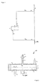
- the schematically shown in Figures 1, 2, 3 and 4 Device for degassing liquids is used, for example, to remove heating water of heating water circulation systems Air and other gases. It is as a centrifuge 10 trained in which the liquid is rotated can be.
- the centrifuge 10 consists essentially from a housing 11 in which a paddle wheel or rotor 12 is rotatably arranged.
- the rotor 12 consists essentially from a perforated support plate 13 for the Liquid inlet 26 and a perforated cover plate 14 for the liquid outlet 20.
- the rotor 12 is provided with blades 15 and in a bearing 16 rotatable.
- the mechanically driven rotor 12 generates a pressure field in the degassing centrifuge 10, the central pressure minimum of which is sufficient for degassing the liquid.
- FIG. 4 shows a degassing centrifuge 10a in which the rotor 12 also as a squirrel cage of an electric Drive motor with a stator winding 17 is used.
- the housing 11 fulfills the function of a containment can. This enables a hermetic construction. But other drive variants are also conceivable.
- the Motor is controlled by a controller 18.
- the housing 11 has a rotor axis 28.
- the perforated cover disk 14 assigned a gas outlet 19 through which the excreted Gas enters a gas collection vessel 27.
- the gas leak 19 need not with the openwork Cover plate 14 may be connected.
- the gas can be removed from the gas collecting vessel 27 via a degassing valve 23 are released into the open atmosphere.
- the degassing valve 23 opens only in the direction the atmosphere.
- the rotation of the rotor 12 makes it heavier Liquid thrown radially outward in the direction of conveyance 21 and degassed in the process.
- the degassed liquid 25 passes back through the liquid outlet 20 the liquid system 29.
- the lighter gas is in Delivery direction 22 radially inwards and over the gas outlet 19 and the degassing valve 23 from the housing 11 derived.
- the housing 11 is via the connection 20 for the gas to be degassed Liquid 24 and via the connection 26 for the degassed liquid 25 with the liquid system to be degassed 29 connected.
- the liquid or the water from the liquid system 29 to be degassed has an inlet pressure p 1 which is equal to, less than or greater than the outlet pressure p 2 of the degassed liquid 25 - depending on whether the degassing centrifuge 10 / 10a is differential pressure, as a pump or Throttle is operated.
- a reduced pressure P 0 which is less than p 1 and p 2 , prevails in the rotor axis 28.
- the reduced pressure p 0 must be below the lowest gas saturation pressure p S of the connected liquid system 29.
- the pressure p 0 can be greater, less than or equal to the atmospheric pressure p b .
- the gas can be discharged through the degassing valve 23 while the degassing centrifuge 10 / 10a is running. If the pressure p 0 is equal to or less than the atmospheric pressure p b , then a stop of the rotor 12 or of the degassing centrifuge 10 / 10a is required for gas discharge through the degassing valve 23.
- the gas discharge is monitored by the controller 18 and can be time-dependent, for example as permanent degassing, Degassing at fixed time intervals or depending on the measured gas content.
- the degassing performance itself can be achieved through the Changing the speeds or by throttling the Flow of the degassing centrifuge or degassing device 10 / 10a can be varied.
Landscapes
- Chemical & Material Sciences (AREA)
- Chemical Kinetics & Catalysis (AREA)
- Centrifugal Separators (AREA)
- Degasification And Air Bubble Elimination (AREA)
Applications Claiming Priority (2)
| Application Number | Priority Date | Filing Date | Title |
|---|---|---|---|
| DE19918831 | 1999-04-22 | ||
| DE19918831 | 1999-04-22 |
Publications (2)
| Publication Number | Publication Date |
|---|---|
| EP1055441A2 true EP1055441A2 (fr) | 2000-11-29 |
| EP1055441A3 EP1055441A3 (fr) | 2001-03-28 |
Family
ID=7905854
Family Applications (1)
| Application Number | Title | Priority Date | Filing Date |
|---|---|---|---|
| EP00250129A Withdrawn EP1055441A3 (fr) | 1999-04-22 | 2000-04-20 | Procédé et dispositif pour dégazer des liquides |
Country Status (1)
| Country | Link |
|---|---|
| EP (1) | EP1055441A3 (fr) |
Cited By (1)
| Publication number | Priority date | Publication date | Assignee | Title |
|---|---|---|---|---|
| RU2636732C1 (ru) * | 2016-06-08 | 2017-11-27 | Федеральное государственное бюджетное учреждение науки Институт теоретической и прикладной механики им. С.А. Христиановича Сибирского отделения Российской академии наук (ИТПМ СО РАН) | Способ выделения растворенных газов из перекачиваемой жидкости и устройство для его реализации (Варианты) |
Family Cites Families (4)
| Publication number | Priority date | Publication date | Assignee | Title |
|---|---|---|---|---|
| DE1025795B (de) * | 1953-01-09 | 1958-03-06 | Freudenberg Carl Kg | Zentrifuge zum Entgasen von Fluessigkeiten |
| GB8304901D0 (en) * | 1982-03-12 | 1983-03-23 | Ici Plc | Displacing dissolved gas from water |
| GB2173712B (en) * | 1985-04-03 | 1989-01-11 | Ici Plc | Degassing of liquids |
| AT396205B (de) * | 1991-09-06 | 1993-07-26 | Andritz Patentverwaltung | Verfahren zum abtrennen von gasfoermigen bestandteilen aus fliessfaehigen medien sowie vorrichtung und anlage dafuer |
-
2000
- 2000-04-20 EP EP00250129A patent/EP1055441A3/fr not_active Withdrawn
Cited By (1)
| Publication number | Priority date | Publication date | Assignee | Title |
|---|---|---|---|---|
| RU2636732C1 (ru) * | 2016-06-08 | 2017-11-27 | Федеральное государственное бюджетное учреждение науки Институт теоретической и прикладной механики им. С.А. Христиановича Сибирского отделения Российской академии наук (ИТПМ СО РАН) | Способ выделения растворенных газов из перекачиваемой жидкости и устройство для его реализации (Варианты) |
Also Published As
| Publication number | Publication date |
|---|---|
| EP1055441A3 (fr) | 2001-03-28 |
Similar Documents
| Publication | Publication Date | Title |
|---|---|---|
| DE19945323B4 (de) | Brennstoffzellensystem | |
| EP0217344B1 (fr) | Séparateur huile-air | |
| EP2830777B2 (fr) | Arrangement de séparateur | |
| WO2008128681A1 (fr) | Dispositif de filtre | |
| DE102004007189A1 (de) | Verfahren zur Luftbehandlung in einem Fahrzeug und Vorrichtung hierfür | |
| DE3021349A1 (de) | Oeldichtungsanordnung fuer die welle eines turboladers | |
| DE102017128483A1 (de) | Flugtriebwerk | |
| EP2821598A1 (fr) | Moteur à réaction doté d'au moins un séparateur d'huile permettant le passage du débit volumique huile/air | |
| DE60317241T2 (de) | Vorrichtung zum rühren einer flüssigkeit und zum einspritzen eines gases in diese flüssigkeit mit einer beschränkten sperrung | |
| EP4038283B1 (fr) | Compresseur comprenant un capteur de détection dans des pompes de compresseur | |
| DE102007042785B4 (de) | Verfahren zum Betrieb einer Brennstoffzelle | |
| EP1055441A2 (fr) | Procédé et dispositif pour dégazer des liquides | |
| DE102010048484A1 (de) | Abscheider für Flüssigkeitströpfchen aus einem Aerosol | |
| DE102007038161B4 (de) | Brennstoffzellensystem | |
| DE19940814A1 (de) | Verfahren und Vorrichtung zum Entgasen von Flüssigkeiten | |
| EP1757816B1 (fr) | Dispositif pour pompes | |
| DE29923258U1 (de) | Vorrichtung zum Entgasen von Flüssigkeiten | |
| EP1559914B1 (fr) | Pompe à effet visqueux | |
| EP0083005B1 (fr) | Dispositif de séparation à membrane plate | |
| DE102023210231A1 (de) | Gebläse für eine Brennstoffzellenanordnung | |
| EP3821972A1 (fr) | Utilisation d'un module filtrant pour filtrer un liquide biotechnologique et module filtrant permettant de filtrer un liquide biotechnologique | |
| DE102015113821B4 (de) | Vakuumpumpe | |
| DE102008050157A1 (de) | Luftversorgungssystem für eine Brennstoffzelle | |
| DE10342808A1 (de) | Turbolader mit Schmiermittelaustrageinrichtung | |
| AT525669B1 (de) | Lagerschmierung einer Schacht-Turbine mittels natürlicher Druckdifferenz |
Legal Events
| Date | Code | Title | Description |
|---|---|---|---|
| PUAI | Public reference made under article 153(3) epc to a published international application that has entered the european phase |
Free format text: ORIGINAL CODE: 0009012 |
|
| AK | Designated contracting states |
Kind code of ref document: A2 Designated state(s): AT BE CH CY DE DK ES FI FR GB GR IE IT LI LU MC NL PT SE |
|
| AX | Request for extension of the european patent |
Free format text: AL;LT;LV;MK;RO;SI |
|
| PUAL | Search report despatched |
Free format text: ORIGINAL CODE: 0009013 |
|
| AK | Designated contracting states |
Kind code of ref document: A3 Designated state(s): AT BE CH CY DE DK ES FI FR GB GR IE IT LI LU MC NL PT SE |
|
| AX | Request for extension of the european patent |
Free format text: AL;LT;LV;MK;RO;SI |
|
| RAP1 | Party data changed (applicant data changed or rights of an application transferred) |
Owner name: REFLEX WINKELMANN + PANNHOFF GMBH + CO. |
|
| 17P | Request for examination filed |
Effective date: 20010912 |
|
| RIN1 | Information on inventor provided before grant (corrected) |
Inventor name: WILL, GOTTHARD, PROF. DR.-ING. HABIL. Inventor name: UHLMANN, DIETRICH, DIPL.-ING. Inventor name: WEISE, HARMUT, PROF. DR.-ING. HABIL. Inventor name: HONKE, MARCUS Inventor name: RUEHLING, KARIN, DR.-ING. |
|
| AKX | Designation fees paid |
Free format text: AT BE CH CY DE DK ES FI FR GB GR IE IT LI LU MC NL PT SE |
|
| STAA | Information on the status of an ep patent application or granted ep patent |
Free format text: STATUS: THE APPLICATION IS DEEMED TO BE WITHDRAWN |
|
| 18D | Application deemed to be withdrawn |
Effective date: 20031104 |