EP1055466A2 - Système d'entraínement hydraulique pour une machine d'assemblage - Google Patents
Système d'entraínement hydraulique pour une machine d'assemblage Download PDFInfo
- Publication number
- EP1055466A2 EP1055466A2 EP00110295A EP00110295A EP1055466A2 EP 1055466 A2 EP1055466 A2 EP 1055466A2 EP 00110295 A EP00110295 A EP 00110295A EP 00110295 A EP00110295 A EP 00110295A EP 1055466 A2 EP1055466 A2 EP 1055466A2
- Authority
- EP
- European Patent Office
- Prior art keywords
- drive
- hold
- working chamber
- pressure
- piston
- Prior art date
- Legal status (The legal status is an assumption and is not a legal conclusion. Google has not performed a legal analysis and makes no representation as to the accuracy of the status listed.)
- Granted
Links
- 238000005304 joining Methods 0.000 claims description 10
- 238000000034 method Methods 0.000 claims description 7
- 239000000463 material Substances 0.000 claims description 3
- 239000012530 fluid Substances 0.000 description 4
- 238000006073 displacement reaction Methods 0.000 description 2
- 238000006243 chemical reaction Methods 0.000 description 1
- 230000001419 dependent effect Effects 0.000 description 1
- 238000003754 machining Methods 0.000 description 1
- 238000004519 manufacturing process Methods 0.000 description 1
- 238000004080 punching Methods 0.000 description 1
- 210000002023 somite Anatomy 0.000 description 1
Images

Classifications
-
- B—PERFORMING OPERATIONS; TRANSPORTING
- B21—MECHANICAL METAL-WORKING WITHOUT ESSENTIALLY REMOVING MATERIAL; PUNCHING METAL
- B21D—WORKING OR PROCESSING OF SHEET METAL OR METAL TUBES, RODS OR PROFILES WITHOUT ESSENTIALLY REMOVING MATERIAL; PUNCHING METAL
- B21D39/00—Application of procedures in order to connect objects or parts, e.g. coating with sheet metal otherwise than by plating; Tube expanders
- B21D39/03—Application of procedures in order to connect objects or parts, e.g. coating with sheet metal otherwise than by plating; Tube expanders of sheet metal otherwise than by folding
- B21D39/031—Joining superposed plates by locally deforming without slitting or piercing
-
- Y—GENERAL TAGGING OF NEW TECHNOLOGICAL DEVELOPMENTS; GENERAL TAGGING OF CROSS-SECTIONAL TECHNOLOGIES SPANNING OVER SEVERAL SECTIONS OF THE IPC; TECHNICAL SUBJECTS COVERED BY FORMER USPC CROSS-REFERENCE ART COLLECTIONS [XRACs] AND DIGESTS
- Y10—TECHNICAL SUBJECTS COVERED BY FORMER USPC
- Y10T—TECHNICAL SUBJECTS COVERED BY FORMER US CLASSIFICATION
- Y10T29/00—Metal working
- Y10T29/49—Method of mechanical manufacture
- Y10T29/49826—Assembling or joining
- Y10T29/49833—Punching, piercing or reaming part by surface of second part
- Y10T29/49835—Punching, piercing or reaming part by surface of second part with shaping
- Y10T29/49837—Punching, piercing or reaming part by surface of second part with shaping of first part
-
- Y—GENERAL TAGGING OF NEW TECHNOLOGICAL DEVELOPMENTS; GENERAL TAGGING OF CROSS-SECTIONAL TECHNOLOGIES SPANNING OVER SEVERAL SECTIONS OF THE IPC; TECHNICAL SUBJECTS COVERED BY FORMER USPC CROSS-REFERENCE ART COLLECTIONS [XRACs] AND DIGESTS
- Y10—TECHNICAL SUBJECTS COVERED BY FORMER USPC
- Y10T—TECHNICAL SUBJECTS COVERED BY FORMER US CLASSIFICATION
- Y10T29/00—Metal working
- Y10T29/53—Means to assemble or disassemble
- Y10T29/53039—Means to assemble or disassemble with control means energized in response to activator stimulated by condition sensor
- Y10T29/53061—Responsive to work or work-related machine element
- Y10T29/53065—Responsive to work or work-related machine element with means to fasten by deformation
- Y10T29/5307—Self-piercing work part
-
- Y—GENERAL TAGGING OF NEW TECHNOLOGICAL DEVELOPMENTS; GENERAL TAGGING OF CROSS-SECTIONAL TECHNOLOGIES SPANNING OVER SEVERAL SECTIONS OF THE IPC; TECHNICAL SUBJECTS COVERED BY FORMER USPC CROSS-REFERENCE ART COLLECTIONS [XRACs] AND DIGESTS
- Y10—TECHNICAL SUBJECTS COVERED BY FORMER USPC
- Y10T—TECHNICAL SUBJECTS COVERED BY FORMER US CLASSIFICATION
- Y10T29/00—Metal working
- Y10T29/53—Means to assemble or disassemble
- Y10T29/53709—Overedge assembling means
- Y10T29/5377—Riveter
Definitions
- the present invention relates to a hydraulic drive device for a tool for joining at least two workpieces made of ductile material, especially for punch riveting or clinching.
- Such drive devices settle usually from a stamp drive for actuating a stamp for the joining process and a hold-down drive for actuating the workpieces during of the holding-down clamp.
- Both drives are designed as a piston-cylinder unit, the cylinders of the two drives are firmly connected and the piston of the hold-down drive between the piston rod of the punch drive and the cylinder of the hold-down drive is arranged concentrically so that it has a pressure chamber with a own pressure medium connection to generate the hold-down force telescopically is movable. Even if the piston of the hold-down drive is standing back Usually a spring is used, but there are a total of three pressure medium connections (two for the punch drive and one for the hold-down drive) required what the drive device and in particular its hydraulic supply comparatively expensive.
- the present invention has for its object a hydraulic Drive device for a tool for joining at least two workpieces to create from ductile material that has the simplest possible structure and nevertheless the generation of a uniform hydraulic hold-down force for The workpieces can be clamped.
- the hold-down drive from the piston rod of the punch drive, and the pressure chamber of the hold-down drive is connected to a working chamber of the stamp drive, so that Generate the hold-down force from this working chamber to the pressure chamber of the hold-down drive is transmitted.
- connection of the relevant working chamber is expedient Stamp drive via a pressure relief valve with a low pressure range connectable to the pressure in the pressure chamber of the hold-down drive and thus limit the hold-down force to an adjustable value.
- the hold-down force is based on the pressure in one working chamber of the punch drive are only two connections to the hydraulic Supply of the entire drive device required.
- Another advantage of Invention is that to increase the feed stroke of hold-down and stamp only the stamp drive must be extended, since then for the hold-down drive carried by the punch drive automatically has a corresponding one Extension of the delivery stroke results. This results overall easier handling and improved access to the drive device.
- the drive device designed according to the invention is also distinguished by comparatively low manufacturing costs, which is simplified by the Structure, the lower number of stroke-dependent parts and a simpler Hydraulic supply are conditional.
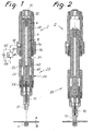
- Figures 1 to 4 each represent a longitudinal section through a hydraulic Drive device in different operating states.
- the drive device shown in the figures is used for punch riveting two plate-shaped workpieces A, B, which are supported on a die M.
- the drive device can also be used for other joining processes, e.g. to the Clinching or generally for machining workpieces by means of a stamp such as used in punching.
- the drive device has a stamp drive 2 in the form of a piston-cylinder unit with a cylinder 4, for example on a C-frame (not shown) is firmly attached.
- a piston 6 with a piston rod 8 slidably mounted.
- the piston 6 divides the interior the cylinder 4 into a first working chamber 12 and a second working chamber 14, each with its own connection 16 or 18 with a hydraulic Pressure medium source (not shown) can be connected.
- the piston rod 8 is fixed at its lower end with a stamp 10 connected, in the illustrated embodiment for performing the riveting process serves.
- the piston rod 8 of the stamp drive 2 carries a hold-down drive in a self-supporting manner 20, which is also designed as a piston-cylinder unit. More accurate said hold-down drive 20 has a piston 22 which is connected to piston rod 8 molded in one piece, that is firmly connected to the piston rod 8.
- the hold-down drive 20 also has a cylinder 24 on the piston rod 8 of the stamp drive 2 is telescopically mounted so that the piston 22 and the Cylinder 24 are slidable relative to each other.
- the cylinder 24 is at its lower end with a hold-down 30 in Form of a mouthpiece firmly connected, in which the stamp 10 is slidably guided and that for holding down (prestressing) the workpieces A, B on the die M serves.
- the cylinder 24 consists of an outer sleeve 26 which is on an upper portion the piston rod 8 is slidably guided, and an inner sleeve 28 which a lower portion of the piston rod 8 is slidably such that between the piston 22, the inner wall of the sleeve 24 and the front end of the Sleeve 28 a pressure chamber 32 is formed.
- the pressure chamber 32 of the hold-down drive 20 is via a flow connection 34 connected to the working chamber 14 of the stamp drive 2.
- the - Always open - flow connection 34 consists of a in the piston rod 8 centrally arranged, longitudinal flow channel 36, the branch channels 38 with the working chamber 8 and via branch channels 40 with the pressure chamber 32 connected is.
- connection 18 is via a pressure relief valve 40 connectable to a low pressure area (tank, not shown), to limit the pressure in the working chamber 8 and thus in the pressure chamber 32, as will be explained in more detail.
- a pressure relief valve 40 connectable to a low pressure area (tank, not shown), to limit the pressure in the working chamber 8 and thus in the pressure chamber 32, as will be explained in more detail.
- the pressure relief valve 40 it is preferably a controllable pressure relief valve, the Limit value can be set manually, for example.
- a check valve 44 through a bypass line 42 to the Pressure relief valve 40 connected in parallel to supply the port 18 with pressure to be able, as will also be explained in more detail.
- the hold-down device presses 30 the workpieces A, B against the die M with a uniform hold-down force, the size of which through the flow connection 34 to the Pressure chamber 32 transmitted, limited by the pressure relief valve 40 Pressure is determined.
- the piston 6 moves with its piston rod 8 and the stamp 10 attached to it further down to finally complete the joining process perform (Fig. 3).
- this further downward movement there is a Relative displacement between the piston provided on the piston rod 8 22 and the cylinder 24 supported on the workpieces A, B of the hold-down drive 20.
- This causes pressure medium from the pressure chamber 32 via the flow connection 34, the working chamber 8 and the port 18 through the pressure relief valve 40 displaced through to the low pressure area.
- the pressure relief valve 40 ensures that the hold-down 30 on the workpieces A, B maintain hold-down force unchanged remains.
- the working chamber 12 is connected 16 relieved of pressure and the working chamber 8 via the connection 18 with pressure supplied so that the piston 6 with the piston rod 8 and the stamp 10 is reset are (Fig. 4).
- the working chamber 8 and the flow connection 34 also the pressure chamber 32 again with hydraulic fluid filled until the drive device again its basic position shown in Fig. 1 occupies.
- the piston rod 8 has in the area of the working chamber 14 an outer diameter that is only slightly smaller than the inner diameter of the cylinder 4 is.
- the displacement volume and the cross-sectional area the working chamber 4 are therefore very small. This ensures that the reaction force caused by the pressure in the working chamber, that of the piston 6 must overcome the punch drive 2 in its feed movement, comparatively is low.
Landscapes
- Engineering & Computer Science (AREA)
- Mechanical Engineering (AREA)
- Actuator (AREA)
- Press Drives And Press Lines (AREA)
- Jigs For Machine Tools (AREA)
- Punching Or Piercing (AREA)
- Automatic Assembly (AREA)
Applications Claiming Priority (2)
| Application Number | Priority Date | Filing Date | Title |
|---|---|---|---|
| DE19924310A DE19924310B4 (de) | 1999-05-27 | 1999-05-27 | Hydraulische Antriebseinrichtung für ein Fügewerkzeug |
| DE19924310 | 1999-05-27 |
Publications (3)
| Publication Number | Publication Date |
|---|---|
| EP1055466A2 true EP1055466A2 (fr) | 2000-11-29 |
| EP1055466A3 EP1055466A3 (fr) | 2002-07-24 |
| EP1055466B1 EP1055466B1 (fr) | 2004-07-21 |
Family
ID=7909359
Family Applications (1)
| Application Number | Title | Priority Date | Filing Date |
|---|---|---|---|
| EP00110295A Expired - Lifetime EP1055466B1 (fr) | 1999-05-27 | 2000-05-23 | Système d'entraínement hydraulique pour une machine d'assemblage |
Country Status (4)
| Country | Link |
|---|---|
| US (1) | US6398096B1 (fr) |
| EP (1) | EP1055466B1 (fr) |
| DE (2) | DE19924310B4 (fr) |
| ES (1) | ES2224962T3 (fr) |
Cited By (3)
| Publication number | Priority date | Publication date | Assignee | Title |
|---|---|---|---|---|
| EP1640081A1 (fr) * | 2004-09-24 | 2006-03-29 | Böllhoff Verbindungstechnik GmbH | Procédé d'assemblage et dispositif de commande d'un outil d'assemblage |
| EP2511023A3 (fr) * | 2011-04-14 | 2016-01-13 | Böllhoff Verbindungstechnik GmbH | Appareil de pose d'éléments de fixation doté d'un agrégat hydraulique et procédé d'assemblage d'au moins deux composants |
| DE102009034542B4 (de) * | 2008-07-23 | 2017-05-24 | Richard Bergner Verbindungstechnik Gmbh & Co. Kg | Bearbeitungseinheit sowie Verfahren für die Bearbeitung eines Werkstücks mit einem Bearbeitungswerkzeug |
Families Citing this family (11)
| Publication number | Priority date | Publication date | Assignee | Title |
|---|---|---|---|---|
| DE10031073B4 (de) * | 2000-06-30 | 2016-11-24 | Gustav Klauke Gmbh | Verfahren zum Vernieten |
| WO2002073045A2 (fr) * | 2001-03-09 | 2002-09-19 | Newfrey Llc | Rivet autoperforant, procede et dispositif pour poser un element rivet et utilisation de ce dernier |
| US20060251495A1 (en) * | 2001-03-09 | 2006-11-09 | Reinhold Opper | Self-piercing rivet, process and device for setting a rivet element, and employment thereof |
| DE20106207U1 (de) * | 2001-04-09 | 2001-06-21 | Böllhoff GmbH, 33649 Bielefeld | Antriebseinrichtung für ein Einpresswerkzeug |
| ITTO20010659A1 (it) * | 2001-07-06 | 2003-01-06 | Comau Spa | Dispositivo integrato di bloccaggio e clinciatura, particolarmente per l'unione di pannelli di lamiera metallica e simili. |
| JP2004060855A (ja) * | 2002-07-31 | 2004-02-26 | Nippon Pop Rivets & Fasteners Ltd | セルフピアシングリベット |
| DE102004005884B4 (de) * | 2004-02-05 | 2012-03-29 | Newfrey Llc | Fügeeinrichtung mit einem Stempelwerkzeug und einem Gegenwerkzeug und einem Halter |
| DE102005041534A1 (de) * | 2005-08-31 | 2007-03-01 | Newfrey Llc, Newark | Verfahren und Vorrichtung zum Zuführen von Verbindungselementen zu einem Verarbeitungsgerät |
| SK932007A3 (sk) * | 2007-07-09 | 2009-02-05 | Konek, S. R. O. | Hydraulické rozrušovacie kladivo |
| CN109454194A (zh) * | 2018-07-27 | 2019-03-12 | 宾科精密部件(中国)有限公司 | 流体压力驱动的压铆装置 |
| DE102021104620B4 (de) | 2021-02-26 | 2023-12-07 | Dieter Schmidt | Krafteinheit für eine Bearbeitungsstation zum Be- und/oder Verarbeiten von Werkstücken und zugehörige Bearbeitungsstation |
Family Cites Families (8)
| Publication number | Priority date | Publication date | Assignee | Title |
|---|---|---|---|---|
| US4096727A (en) * | 1976-04-29 | 1978-06-27 | Daniel Pierre Gargaillo | Punching, stamping and rivetting apparatus |
| US4516448A (en) * | 1982-09-07 | 1985-05-14 | Houdaille Industries, Inc. | Punch and ram assembly for punch press |
| GB9211785D0 (en) * | 1992-06-04 | 1992-07-15 | Ariel Ind Plc | Improved design of fastener application machine |
| GB9226517D0 (en) * | 1992-12-19 | 1993-02-10 | Henrob Ltd | Improvements in or relating to sefl-piercing riveting |
| SE9303824L (sv) * | 1993-11-18 | 1994-10-10 | Pressmaster Tool Ab | Förfarande för drivning av ett hydrauliskt arbetsverktyg och anordning för genomförande av förfarandet |
| US6276050B1 (en) * | 1998-07-20 | 2001-08-21 | Emhart Inc. | Riveting system and process for forming a riveted joint |
| ES2193444T3 (es) * | 1997-07-26 | 2003-11-01 | Eibes Kerb Konus Gmbh | Hokramienta de estampado y corte. |
| DE19752367A1 (de) * | 1997-11-26 | 1999-05-27 | Emhart Inc | Verfahren und Vorrichtung zur Herstellung einer Stanznietverbindung |
-
1999
- 1999-05-27 DE DE19924310A patent/DE19924310B4/de not_active Expired - Fee Related
-
2000
- 2000-05-23 DE DE50007105T patent/DE50007105D1/de not_active Expired - Fee Related
- 2000-05-23 EP EP00110295A patent/EP1055466B1/fr not_active Expired - Lifetime
- 2000-05-23 ES ES00110295T patent/ES2224962T3/es not_active Expired - Lifetime
- 2000-05-26 US US09/579,802 patent/US6398096B1/en not_active Expired - Fee Related
Cited By (5)
| Publication number | Priority date | Publication date | Assignee | Title |
|---|---|---|---|---|
| EP1640081A1 (fr) * | 2004-09-24 | 2006-03-29 | Böllhoff Verbindungstechnik GmbH | Procédé d'assemblage et dispositif de commande d'un outil d'assemblage |
| KR100794637B1 (ko) * | 2004-09-24 | 2008-01-14 | 뵐호프 베르빈둥스테크니크 게엠베하 | 체결 공구용 접합 방법 및 장치 |
| US7475473B2 (en) | 2004-09-24 | 2009-01-13 | Bollhoff Verbindungstechnik Gmbh | Device for operating a fastening tool |
| DE102009034542B4 (de) * | 2008-07-23 | 2017-05-24 | Richard Bergner Verbindungstechnik Gmbh & Co. Kg | Bearbeitungseinheit sowie Verfahren für die Bearbeitung eines Werkstücks mit einem Bearbeitungswerkzeug |
| EP2511023A3 (fr) * | 2011-04-14 | 2016-01-13 | Böllhoff Verbindungstechnik GmbH | Appareil de pose d'éléments de fixation doté d'un agrégat hydraulique et procédé d'assemblage d'au moins deux composants |
Also Published As
| Publication number | Publication date |
|---|---|
| DE50007105D1 (de) | 2004-08-26 |
| EP1055466A3 (fr) | 2002-07-24 |
| EP1055466B1 (fr) | 2004-07-21 |
| ES2224962T3 (es) | 2005-03-16 |
| DE19924310A1 (de) | 2000-11-30 |
| DE19924310B4 (de) | 2007-11-22 |
| US6398096B1 (en) | 2002-06-04 |
Similar Documents
| Publication | Publication Date | Title |
|---|---|---|
| EP1640081B2 (fr) | Procédé d'assemblage et dispositif de commande d'un outil d'assemblage | |
| DE10206630B4 (de) | Verfahren und Vorrichtung zum Hochgeschwindigkeitspressen von Werkstücken | |
| EP1055466B1 (fr) | Système d'entraínement hydraulique pour une machine d'assemblage | |
| DE1920184C3 (de) | Vorrichtung zum gleichzeitigen und gleichmäßigen Bewegen mehrerer, durch Druckmittel betriebener Arbeitszylinder | |
| DE2818337B1 (de) | Druckuebersetzter hydropneumatischer Antrieb | |
| DE2718776C2 (de) | Mit einem ersten Druckmittel betätigte Vorrichtung zur Erhöhung des Druckes eines zweiten Druckmittels in zwei Stufen | |
| EP1247599A1 (fr) | Dispositif d' entraínement pour outil d' insertion | |
| EP1385652B1 (fr) | Dispositif de serrage hydromecanique servant notamment a l'extrusion laterale | |
| EP2511023B1 (fr) | Appareil de pose d'éléments de fixation doté d'un agrégat hydraulique et procédé d'assemblage d'au moins deux composants | |
| DE2600948A1 (de) | Vorrichtung zum erzeugen einer schlagartigen belastung eines zu bearbeitenden und/oder zu verformenden koerpers | |
| DE10260110B4 (de) | Vorrichtung zum Stanzen | |
| CH655024A5 (de) | Einrichtung zum herstellen von durchzuegen an aus blech bestehenden werkstuecken auf einer schneidpresse. | |
| DE102009034542B4 (de) | Bearbeitungseinheit sowie Verfahren für die Bearbeitung eines Werkstücks mit einem Bearbeitungswerkzeug | |
| WO2010051913A1 (fr) | Convertisseur de forces hydraulique | |
| DE10359879A1 (de) | Hydraulische Bearbeitungszange | |
| EP0417753A2 (fr) | Presse mécanique ou hydraulique avec dispositif d'étirage ou d'emboutissage pour presse à plusieurs étapes | |
| EP1984132B1 (fr) | Pince d'usinage hydraulique | |
| EP0245371B2 (fr) | Organe d'appui pour une presse a decouper | |
| DE19645627C2 (de) | Hydraulische Presse | |
| DE1270906B (de) | Steuerschieber | |
| DE10030792C2 (de) | Mehrstufenpresse, insbesondere Quertransportpresse, mit hydraulischer Schließvorrichtung | |
| EP0251024A2 (fr) | Outil d'étirage | |
| DE202009008413U1 (de) | Werkzeugsystem für eine Umformpresse | |
| DE3119307A1 (de) | "druckverstaerker" | |
| DD281142A5 (de) | Hydraulisch interne folgeschaltung fuer einen satellitenrundschalttisch |
Legal Events
| Date | Code | Title | Description |
|---|---|---|---|
| PUAI | Public reference made under article 153(3) epc to a published international application that has entered the european phase |
Free format text: ORIGINAL CODE: 0009012 |
|
| AK | Designated contracting states |
Kind code of ref document: A2 Designated state(s): AT BE CH CY DE DK ES FI FR GB GR IE IT LI LU MC NL PT SE |
|
| AX | Request for extension of the european patent |
Free format text: AL;LT;LV;MK;RO;SI |
|
| PUAL | Search report despatched |
Free format text: ORIGINAL CODE: 0009013 |
|
| AK | Designated contracting states |
Kind code of ref document: A3 Designated state(s): AT BE CH CY DE DK ES FI FR GB GR IE IT LI LU MC NL PT SE |
|
| AX | Request for extension of the european patent |
Free format text: AL;LT;LV;MK;RO;SI |
|
| RIC1 | Information provided on ipc code assigned before grant |
Free format text: 7B 21D 39/03 A, 7B 21J 15/20 B |
|
| 17P | Request for examination filed |
Effective date: 20030116 |
|
| AKX | Designation fees paid |
Designated state(s): DE ES FR GB IT SE |
|
| GRAP | Despatch of communication of intention to grant a patent |
Free format text: ORIGINAL CODE: EPIDOSNIGR1 |
|
| GRAS | Grant fee paid |
Free format text: ORIGINAL CODE: EPIDOSNIGR3 |
|
| GRAA | (expected) grant |
Free format text: ORIGINAL CODE: 0009210 |
|
| AK | Designated contracting states |
Kind code of ref document: B1 Designated state(s): DE ES FR GB IT SE |
|
| REG | Reference to a national code |
Ref country code: GB Ref legal event code: FG4D Free format text: NOT ENGLISH |
|
| REG | Reference to a national code |
Ref country code: IE Ref legal event code: FG4D Free format text: GERMAN |
|
| REF | Corresponds to: |
Ref document number: 50007105 Country of ref document: DE Date of ref document: 20040826 Kind code of ref document: P |
|
| REG | Reference to a national code |
Ref country code: SE Ref legal event code: TRGR |
|
| REG | Reference to a national code |
Ref country code: ES Ref legal event code: FG2A Ref document number: 2224962 Country of ref document: ES Kind code of ref document: T3 |
|
| REG | Reference to a national code |
Ref country code: IE Ref legal event code: FD4D |
|
| PGFP | Annual fee paid to national office [announced via postgrant information from national office to epo] |
Ref country code: DE Payment date: 20050504 Year of fee payment: 6 |
|
| PGFP | Annual fee paid to national office [announced via postgrant information from national office to epo] |
Ref country code: GB Payment date: 20050512 Year of fee payment: 6 |
|
| PGFP | Annual fee paid to national office [announced via postgrant information from national office to epo] |
Ref country code: FR Payment date: 20050519 Year of fee payment: 6 |
|
| PGFP | Annual fee paid to national office [announced via postgrant information from national office to epo] |
Ref country code: SE Payment date: 20050524 Year of fee payment: 6 |
|
| ET | Fr: translation filed | ||
| PLBE | No opposition filed within time limit |
Free format text: ORIGINAL CODE: 0009261 |
|
| STAA | Information on the status of an ep patent application or granted ep patent |
Free format text: STATUS: NO OPPOSITION FILED WITHIN TIME LIMIT |
|
| PGFP | Annual fee paid to national office [announced via postgrant information from national office to epo] |
Ref country code: ES Payment date: 20050531 Year of fee payment: 6 |
|
| 26N | No opposition filed |
Effective date: 20050422 |
|
| PG25 | Lapsed in a contracting state [announced via postgrant information from national office to epo] |
Ref country code: GB Free format text: LAPSE BECAUSE OF NON-PAYMENT OF DUE FEES Effective date: 20060523 |
|
| PG25 | Lapsed in a contracting state [announced via postgrant information from national office to epo] |
Ref country code: SE Free format text: LAPSE BECAUSE OF NON-PAYMENT OF DUE FEES Effective date: 20060524 Ref country code: ES Free format text: LAPSE BECAUSE OF NON-PAYMENT OF DUE FEES Effective date: 20060524 |
|
| PGFP | Annual fee paid to national office [announced via postgrant information from national office to epo] |
Ref country code: IT Payment date: 20060531 Year of fee payment: 7 |
|
| PG25 | Lapsed in a contracting state [announced via postgrant information from national office to epo] |
Ref country code: DE Free format text: LAPSE BECAUSE OF NON-PAYMENT OF DUE FEES Effective date: 20061201 |
|
| EUG | Se: european patent has lapsed | ||
| GBPC | Gb: european patent ceased through non-payment of renewal fee |
Effective date: 20060523 |
|
| REG | Reference to a national code |
Ref country code: FR Ref legal event code: ST Effective date: 20070131 |
|
| REG | Reference to a national code |
Ref country code: ES Ref legal event code: FD2A Effective date: 20060524 |
|
| PG25 | Lapsed in a contracting state [announced via postgrant information from national office to epo] |
Ref country code: FR Free format text: LAPSE BECAUSE OF NON-PAYMENT OF DUE FEES Effective date: 20060531 |
|
| PG25 | Lapsed in a contracting state [announced via postgrant information from national office to epo] |
Ref country code: IT Free format text: LAPSE BECAUSE OF NON-PAYMENT OF DUE FEES Effective date: 20070523 |