EP1055475A2 - Mehrspindelwerkzeugmaschine - Google Patents
Mehrspindelwerkzeugmaschine Download PDFInfo
- Publication number
- EP1055475A2 EP1055475A2 EP00110767A EP00110767A EP1055475A2 EP 1055475 A2 EP1055475 A2 EP 1055475A2 EP 00110767 A EP00110767 A EP 00110767A EP 00110767 A EP00110767 A EP 00110767A EP 1055475 A2 EP1055475 A2 EP 1055475A2
- Authority
- EP
- European Patent Office
- Prior art keywords
- main spindle
- tool main
- frame member
- housing
- work
- Prior art date
- Legal status (The legal status is an assumption and is not a legal conclusion. Google has not performed a legal analysis and makes no representation as to the accuracy of the status listed.)
- Withdrawn
Links
- 230000020347 spindle assembly Effects 0.000 claims abstract description 80
- 238000012545 processing Methods 0.000 claims abstract description 50
- 238000003780 insertion Methods 0.000 claims abstract description 32
- 230000037431 insertion Effects 0.000 claims abstract description 32
- 230000002093 peripheral effect Effects 0.000 claims description 15
- 238000012986 modification Methods 0.000 abstract description 11
- 230000004048 modification Effects 0.000 abstract description 11
- 230000008859 change Effects 0.000 abstract description 7
- 238000013461 design Methods 0.000 abstract description 2
- 238000010276 construction Methods 0.000 description 7
- 238000003801 milling Methods 0.000 description 2
- 230000004044 response Effects 0.000 description 2
- 238000010348 incorporation Methods 0.000 description 1
- 238000012423 maintenance Methods 0.000 description 1
- 238000000034 method Methods 0.000 description 1
- 230000008569 process Effects 0.000 description 1
Images


Classifications
-
- B—PERFORMING OPERATIONS; TRANSPORTING
- B23—MACHINE TOOLS; METAL-WORKING NOT OTHERWISE PROVIDED FOR
- B23B—TURNING; BORING
- B23B39/00—General-purpose boring or drilling machines or devices; Sets of boring and/or drilling machines
- B23B39/16—Drilling machines with a plurality of working-spindles; Drilling automatons
- B23B39/20—Setting work or tool carrier along a circular index line; Turret head drilling machines
-
- B—PERFORMING OPERATIONS; TRANSPORTING
- B23—MACHINE TOOLS; METAL-WORKING NOT OTHERWISE PROVIDED FOR
- B23P—METAL-WORKING NOT OTHERWISE PROVIDED FOR; COMBINED OPERATIONS; UNIVERSAL MACHINE TOOLS
- B23P23/00—Machines or arrangements of machines for performing specified combinations of different metal-working operations not covered by a single other subclass
-
- B—PERFORMING OPERATIONS; TRANSPORTING
- B23—MACHINE TOOLS; METAL-WORKING NOT OTHERWISE PROVIDED FOR
- B23B—TURNING; BORING
- B23B39/00—General-purpose boring or drilling machines or devices; Sets of boring and/or drilling machines
- B23B39/16—Drilling machines with a plurality of working-spindles; Drilling automatons
- B23B39/161—Drilling machines with a plurality of working-spindles; Drilling automatons with parallel work spindles
-
- B—PERFORMING OPERATIONS; TRANSPORTING
- B23—MACHINE TOOLS; METAL-WORKING NOT OTHERWISE PROVIDED FOR
- B23Q—DETAILS, COMPONENTS, OR ACCESSORIES FOR MACHINE TOOLS, e.g. ARRANGEMENTS FOR COPYING OR CONTROLLING; MACHINE TOOLS IN GENERAL CHARACTERISED BY THE CONSTRUCTION OF PARTICULAR DETAILS OR COMPONENTS; COMBINATIONS OR ASSOCIATIONS OF METAL-WORKING MACHINES, NOT DIRECTED TO A PARTICULAR RESULT
- B23Q39/00—Metal-working machines incorporating a plurality of sub-assemblies, each capable of performing a metal-working operation
- B23Q39/04—Metal-working machines incorporating a plurality of sub-assemblies, each capable of performing a metal-working operation the sub-assemblies being arranged to operate simultaneously at different stations, e.g. with an annular work-table moved in steps
-
- B—PERFORMING OPERATIONS; TRANSPORTING
- B23—MACHINE TOOLS; METAL-WORKING NOT OTHERWISE PROVIDED FOR
- B23Q—DETAILS, COMPONENTS, OR ACCESSORIES FOR MACHINE TOOLS, e.g. ARRANGEMENTS FOR COPYING OR CONTROLLING; MACHINE TOOLS IN GENERAL CHARACTERISED BY THE CONSTRUCTION OF PARTICULAR DETAILS OR COMPONENTS; COMBINATIONS OR ASSOCIATIONS OF METAL-WORKING MACHINES, NOT DIRECTED TO A PARTICULAR RESULT
- B23Q39/00—Metal-working machines incorporating a plurality of sub-assemblies, each capable of performing a metal-working operation
- B23Q39/04—Metal-working machines incorporating a plurality of sub-assemblies, each capable of performing a metal-working operation the sub-assemblies being arranged to operate simultaneously at different stations, e.g. with an annular work-table moved in steps
- B23Q39/042—Metal-working machines incorporating a plurality of sub-assemblies, each capable of performing a metal-working operation the sub-assemblies being arranged to operate simultaneously at different stations, e.g. with an annular work-table moved in steps with circular arrangement of the sub-assemblies
-
- B—PERFORMING OPERATIONS; TRANSPORTING
- B23—MACHINE TOOLS; METAL-WORKING NOT OTHERWISE PROVIDED FOR
- B23Q—DETAILS, COMPONENTS, OR ACCESSORIES FOR MACHINE TOOLS, e.g. ARRANGEMENTS FOR COPYING OR CONTROLLING; MACHINE TOOLS IN GENERAL CHARACTERISED BY THE CONSTRUCTION OF PARTICULAR DETAILS OR COMPONENTS; COMBINATIONS OR ASSOCIATIONS OF METAL-WORKING MACHINES, NOT DIRECTED TO A PARTICULAR RESULT
- B23Q5/00—Driving or feeding mechanisms; Control arrangements therefor
- B23Q5/02—Driving main working members
- B23Q5/04—Driving main working members rotary shafts, e.g. working-spindles
- B23Q5/10—Driving main working members rotary shafts, e.g. working-spindles driven essentially by electrical means
-
- B—PERFORMING OPERATIONS; TRANSPORTING
- B23—MACHINE TOOLS; METAL-WORKING NOT OTHERWISE PROVIDED FOR
- B23Q—DETAILS, COMPONENTS, OR ACCESSORIES FOR MACHINE TOOLS, e.g. ARRANGEMENTS FOR COPYING OR CONTROLLING; MACHINE TOOLS IN GENERAL CHARACTERISED BY THE CONSTRUCTION OF PARTICULAR DETAILS OR COMPONENTS; COMBINATIONS OR ASSOCIATIONS OF METAL-WORKING MACHINES, NOT DIRECTED TO A PARTICULAR RESULT
- B23Q5/00—Driving or feeding mechanisms; Control arrangements therefor
- B23Q5/22—Feeding members carrying tools or work
- B23Q5/34—Feeding other members supporting tools or work, e.g. saddles, tool-slides, through mechanical transmission
- B23Q5/38—Feeding other members supporting tools or work, e.g. saddles, tool-slides, through mechanical transmission feeding continuously
- B23Q5/40—Feeding other members supporting tools or work, e.g. saddles, tool-slides, through mechanical transmission feeding continuously by feed shaft, e.g. lead screw
-
- Y—GENERAL TAGGING OF NEW TECHNOLOGICAL DEVELOPMENTS; GENERAL TAGGING OF CROSS-SECTIONAL TECHNOLOGIES SPANNING OVER SEVERAL SECTIONS OF THE IPC; TECHNICAL SUBJECTS COVERED BY FORMER USPC CROSS-REFERENCE ART COLLECTIONS [XRACs] AND DIGESTS
- Y10—TECHNICAL SUBJECTS COVERED BY FORMER USPC
- Y10T—TECHNICAL SUBJECTS COVERED BY FORMER US CLASSIFICATION
- Y10T29/00—Metal working
- Y10T29/51—Plural diverse manufacturing apparatus including means for metal shaping or assembling
- Y10T29/5168—Multiple-tool holder
-
- Y—GENERAL TAGGING OF NEW TECHNOLOGICAL DEVELOPMENTS; GENERAL TAGGING OF CROSS-SECTIONAL TECHNOLOGIES SPANNING OVER SEVERAL SECTIONS OF THE IPC; TECHNICAL SUBJECTS COVERED BY FORMER USPC CROSS-REFERENCE ART COLLECTIONS [XRACs] AND DIGESTS
- Y10—TECHNICAL SUBJECTS COVERED BY FORMER USPC
- Y10T—TECHNICAL SUBJECTS COVERED BY FORMER US CLASSIFICATION
- Y10T29/00—Metal working
- Y10T29/51—Plural diverse manufacturing apparatus including means for metal shaping or assembling
- Y10T29/5168—Multiple-tool holder
- Y10T29/5171—Axial tool and transversely movable slide rest
- Y10T29/5172—Rotary tool spindle
-
- Y—GENERAL TAGGING OF NEW TECHNOLOGICAL DEVELOPMENTS; GENERAL TAGGING OF CROSS-SECTIONAL TECHNOLOGIES SPANNING OVER SEVERAL SECTIONS OF THE IPC; TECHNICAL SUBJECTS COVERED BY FORMER USPC CROSS-REFERENCE ART COLLECTIONS [XRACs] AND DIGESTS
- Y10—TECHNICAL SUBJECTS COVERED BY FORMER USPC
- Y10T—TECHNICAL SUBJECTS COVERED BY FORMER US CLASSIFICATION
- Y10T29/00—Metal working
- Y10T29/51—Plural diverse manufacturing apparatus including means for metal shaping or assembling
- Y10T29/5168—Multiple-tool holder
- Y10T29/5173—Longitudinally and transversely movable
- Y10T29/5174—Rotary tool spindle
-
- Y—GENERAL TAGGING OF NEW TECHNOLOGICAL DEVELOPMENTS; GENERAL TAGGING OF CROSS-SECTIONAL TECHNOLOGIES SPANNING OVER SEVERAL SECTIONS OF THE IPC; TECHNICAL SUBJECTS COVERED BY FORMER USPC CROSS-REFERENCE ART COLLECTIONS [XRACs] AND DIGESTS
- Y10—TECHNICAL SUBJECTS COVERED BY FORMER USPC
- Y10T—TECHNICAL SUBJECTS COVERED BY FORMER US CLASSIFICATION
- Y10T408/00—Cutting by use of rotating axially moving tool
- Y10T408/36—Machine including plural tools
- Y10T408/38—Plural, simultaneously operational tools
-
- Y—GENERAL TAGGING OF NEW TECHNOLOGICAL DEVELOPMENTS; GENERAL TAGGING OF CROSS-SECTIONAL TECHNOLOGIES SPANNING OVER SEVERAL SECTIONS OF THE IPC; TECHNICAL SUBJECTS COVERED BY FORMER USPC CROSS-REFERENCE ART COLLECTIONS [XRACs] AND DIGESTS
- Y10—TECHNICAL SUBJECTS COVERED BY FORMER USPC
- Y10T—TECHNICAL SUBJECTS COVERED BY FORMER US CLASSIFICATION
- Y10T408/00—Cutting by use of rotating axially moving tool
- Y10T408/36—Machine including plural tools
- Y10T408/38—Plural, simultaneously operational tools
- Y10T408/3811—Plural, simultaneously operational tools with provision for adjustment of relationship of axes
-
- Y—GENERAL TAGGING OF NEW TECHNOLOGICAL DEVELOPMENTS; GENERAL TAGGING OF CROSS-SECTIONAL TECHNOLOGIES SPANNING OVER SEVERAL SECTIONS OF THE IPC; TECHNICAL SUBJECTS COVERED BY FORMER USPC CROSS-REFERENCE ART COLLECTIONS [XRACs] AND DIGESTS
- Y10—TECHNICAL SUBJECTS COVERED BY FORMER USPC
- Y10T—TECHNICAL SUBJECTS COVERED BY FORMER US CLASSIFICATION
- Y10T409/00—Gear cutting, milling, or planing
- Y10T409/30—Milling
- Y10T409/306664—Milling including means to infeed rotary cutter toward work
- Y10T409/307784—Plural cutters
-
- Y—GENERAL TAGGING OF NEW TECHNOLOGICAL DEVELOPMENTS; GENERAL TAGGING OF CROSS-SECTIONAL TECHNOLOGIES SPANNING OVER SEVERAL SECTIONS OF THE IPC; TECHNICAL SUBJECTS COVERED BY FORMER USPC CROSS-REFERENCE ART COLLECTIONS [XRACs] AND DIGESTS
- Y10—TECHNICAL SUBJECTS COVERED BY FORMER USPC
- Y10T—TECHNICAL SUBJECTS COVERED BY FORMER US CLASSIFICATION
- Y10T409/00—Gear cutting, milling, or planing
- Y10T409/30—Milling
- Y10T409/30784—Milling including means to adustably position cutter
- Y10T409/308568—Plural cutters
Definitions
- the present invention relates to a multiple spindle processing unit for simultaneously processing a plurality of processing locations of a work.
- Japanese Utility Model Publication No. HEI 55-21835 discloses a multiple spindle head wherein a plurality of cylindrical housings journaling tool main spindles are removably secured to a case so as to easily contend with a modification made to a work.
- an end of a drive shaft journaled in a body for securing the case to an opening end surface is connected to ends of the tool main spindles by means of gears, and all the tool main spindles are driven by a single motor.
- This multiple spindle head makes it possible to contend with a modification made to a work by arranging the housings journaling the tool main spindles at positions corresponding to processing locations of the work.
- a great deal of labor and craftsmanship are required to arrange the gears and determine the number of gears such that the tool main spindles arbitrarily arranged in accordance with the processing locations of the work are driven in a desired rotational direction and at a desired rotational speed.
- Such a modification leads to problems such as an increase in the number of required parts, complication of assembly operations, a resultant increase in costs, and undesirable maintainability.
- Outwardly extending flanges are formed at openings of the housings. The housings are fastened at the flanges to the case by means of bolts. Therefore, the minimum distance among the tool main spindles cannot be reduced beyond a certain limit, and in some cases, it is impossible to handle a work whose processing locations are close to one another.
- a multiple spindle processing unit comprising a housing, a main spindle which is coaxially and rotationally journaled by the housing and which has a front end portion where a chuck for mounting a tool is provided, a plurality of tool main spindle assemblies each composed of a built-in motor which is built into the housing to rotationally drive the main spindle, and a frame member which is guided and supported so as to be moved towards or away from a work and which has insertion holes for removably mounting the tool main spindle assemblies at a plurality of locations corresponding to a plurality of processing locations of the work.
- the built-in motors for rotationally driving the main spindles are built into the housings correspondingly. Therefore, in order to change arrangement of the main spindles in response to a change in processing locations of the work, it is required just to replace the insertion holes formed in the frame member with those corresponding to the processing locations of the work and rearrange the tool main spindle assemblies journaling the main spindles.
- the multiple spindle processing unit may further comprise a holding plate which is divided into a plurality of portions and which securely sandwiches the housing of each of the tool main spindle assemblies.
- the tool main spindle assembly may removably be mounted to the frame member through the holding plate with the housing inserted through the insertion hole. This construction makes it possible to arrange the tool main spindle assemblies very close to one another.
- a flange may integrally be formed to radially protrude from an outer peripheral surface of the housing of each of the tool main spindle assemblies, and the tool main spindle assembly may removably be mounted to the frame member through the flange with the housing inserted through the insertion hole. This construction dispenses with a separate holding plate.
- some of the tool main spindle assemblies may be mounted to the frame member with the flange in close contact with one side surface of the frame member, and the other tool main spindle assemblies may be mounted to the frame member with the flange in close contact with the other side surface of the frame member.
- the flanges located on opposed sides of the frame member do not interfere with each other.
- the flange may be formed to protrude from the housing on diametrically opposed sides.
- the width of the flange can be reduced in the direction perpendicular to the direction in which the flange protrudes.
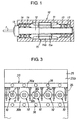
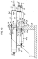
- a frame member 25 is slidably guided and supported on a bed 20 in a direction X in which the frame member 25 is moved towards or away from a work (not shown) through a slide 21.
- the frame member 25 supports five tool main spindle assemblies 10 aligned laterally.
- the frame member 25 is reciprocated by a ball screw 26 and a nut (not shown) into which the ball screw 26 is screwed.
- the ball screw 26 is supported by the bed 20 in a manner exclusively allowing rotational movements and is rotationally driven by a motor 27.
- the nut is provided on a lower surface of the frame member 25.
- each of the tool main spindle assemblies 10 has a cylindrical housing 11 into which a plurality of parts are integrated.
- a main spindle 12 is rotatably journaled to be coaxial with a housing through ball bearings 16, 17.
- the ball bearings 16, 17 are provided at opposed end portions of the main spindle 12.
- a chuck 13, which removably holds a tool T, is coaxially mounted to a front end of the main spindle 12 protruding from one end of the housing 11.
- the main spindle 12 is rotationally driven by a built-in motor 15 that is built into the housing 11.
- the built-in motor 15 is composed of a rotor 15A fixed to the main spindle 12 and a stator 15b fixed to the housing 11.
- the housing 11 is inserted through an insertion hole 25A formed in the frame member 25 and is fixed to the frame member 25 through a holding plate 30.
- five insertion holes 25A are formed in the work at a plurality of processing locations.
- the insertion holes 25A are through-holes which are aligned laterally at an equal pitch.
- the holding plate 30 is composed of a pair of half portions 30a, 30b which are vertically opposed to each other.
- Five semicircular recesses 30c are formed along a joining edge of each of the half portions 30a, 30b. These recesses 30c receive outer peripheral surfaces of the housings 11 of the tool main spindle assemblies 10 substantially airtightly.
- the recesses 30c are arranged at the same pitch as the insertion holes 25a.
- the half portions 30a, 30b are integrally coupled to each other.
- the half portions 30a, 30b are obtained by forming five through-holes substantially identical to the insertion holes 25a in the holding plate 30 and cutting it in halves along a plane passing through center lines of the through-holes by means of a milling cutter or the like.
- the tool main spindle assemblies 10 are securely sandwiched between the half portions 30a, 30b of the holding plate 30.
- This state is realized by fitting the outer peripheral surfaces of the housings 11 onto inner peripheral surfaces of the recesses 30c, joining the housings 11 to the half portions 30a, 30b, and tightening clamping bolts 35 which are provided between the recesses 30c and at opposed end portions.
- a cutting allowance generated in cutting the holding plate 30 with the aforementioned milling cutter or the like constitutes an interference in securely sandwiching the tool main spindle assemblies 10 between the half portions 30a, 30b.
- Each of the tool main spindle assemblies 10 is securely sandwiched between the half portions 30a, 30b of the holding plate 30 with the housing 11 inserted through the insertion hole 25a in the frame member 25, and is removably mounted to the frame member 25 by clamping the holding plate 30 by means of a mounting bolt 36.
- the tools T shown Figs. 3 and 4 are similar to one another, they actually correspond to processing locations of the works.
- Each of the tool main spindle assemblies 10 protrudes from the frame member 25 by a distance that differs depending on a processing location of the work.
- the tool main spindle assemblies 10 may securely be sandwiched between the half portions 30a, 30b of the holding plate 30 before the housings 11 are inserted through the insertion holes 25a. That is, the housings 11 may be inserted through the insertion holes 25a after the tool main spindle assemblies 10 have securely been sandwiched between the half portions 30a, 30b of the holding plate 30, so as to securely clamp the holding plate 30 onto the frame member 25 by means of mounting bolts 36.
- the precision in processing the half portions 30a, 30b is enhanced, works can be processed with required precision even in the case where the insertion holes 25a formed in the frame member 25 are rough and large.
- the tool main spindle assemblies 10 thus fixed to the frame member 25 process a work at various locations by rotationally driving the main spindles 12 and the tools T by means of the built-in motors 15 and advancing the frame member 25 towards the work by means of the motors 27.
- the first embodiment only requires replacing the insertion holes 25a formed in the frame member 25 and the holding plate 30 with those corresponding to the processing locations of the work and changing arrangement of the tool main spindle assemblies 10 journaling the main spindles 12. Therefore, the multiple spindle processing unit can easily be designed in accordance with such a change. The number of additional parts required by such a change is comparatively small. If one of the tool main spindle assemblies 10 is out of order, it is required just to exchange that tool main spindle assembly 10 independently of the other ones. Therefore, it is easy to provide maintenance for the multiple spindle processing unit.
- the housings 11 are not required to take the shape of a circular cylinder.
- the housings 11 may be in the shape of a polygonal cylinder.
- the housings 11 assume such a shape that the recesses 30c in the half portions of the holding plate 30 receive the outer peripheral surfaces of the housings 11 of the tool main spindle assemblies 10 substantially air tightly.
- the second embodiment is different from the first embodiment only in the following respects. That is, the insertion holes 25a formed in the frame member 25 (only one reference numeral is shown in Fig. 5) are arranged triangularly in accordance with processing locations of a work. A holding plate 31 is provided separately for each of the insertion holes 25a, and one tool main spindle assembly 10 is securely sandwiched between half portions 31a, 31b of the holding plate 31 and removably mounted to the frame member 25.
- the construction of the second embodiment is identical to that of the first embodiment. Therefore, components of the second embodiment identical to those of the first embodiment are denoted by the same reference numerals and will not be described in detail.
- the second embodiment only requires changing the frame member 25 when modifications are made to a work. That is, the holding plates 31 are commonly used despite such modifications made to the work. Thus, in the second embodiment, the number of parts required for such modifications is further reduced.
- the holding plates 31 are mounted to one side surface of the frame member 25 opposed to a work (see one side surface 25b in Fig. 2). However, it is also possible to mount some of the holding plates 31 to one side surface opposed to the work and the other holding plates 31 to the other side surface of the frame member 25 (see the other side surface 25c in Fig. 2). In the case where all the holding plates 31 are mounted to one side surface 25b of the frame member 25, the holding plates 31 cannot be arranged to overlap with one another because they interfere with one another.
- the holding plates 31 mounted to one side surface of the frame member 25 do not interfere with the holding plates 31 mounted to the other side surface of the frame member 25.
- the holding members 31 can be arranged to overlap with each other with the frame member 25 interposed therebetween. This makes it possible to arrange the tool main spindle assemblies 10 to such an extent that they come into close contact with the holding plates 31 on the opposite side surface. Therefore, the tool main spindle assemblies 10 supported by the holding plates 31 on the opposite side of the frame member 25 can be located closer to one another in comparison with the case where all the holding plates 31 are mounted to one side surface of the frame member 25. That is, it is possible to locate the tool main spindle assemblies 10 close to one another and handle a work whose processing locations are close to one another.
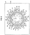
- the insertion holes 25a formed in the frame member 25 are arranged in the shape of an equilateral octagon in accordance with processing locations of a work.
- a holding plate 32 is composed of a common body portion 32a and eight clamp portions 32b.
- the body portion 32a is in the shape of an equilateral octagon with eight sides each having a recess 32c.
- the eight recesses 32c respectively correspond to the insertion holes 25a formed in the frame member 25.
- Each of the clamp portions 32b has a recess 32d corresponding to the recess 32c.
- the outer peripheral surfaces of the housings 11 are brought into close contact with the recesses 32c in the body portion 32a and the recesses 32d in the clamp portions 32b, and the clamp portions 32b are tightened by means of the clamping bolts 35.
- the tool main spindle assemblies 10 are securely sandwiched between the body portion 32a and the clamp portions 32b, and the holding plate 32 is removably mounted to the frame member 25 by means of mounting bolts 36a, 36b.
- the construction of the third embodiment is identical to that of the first embodiment. Therefore, components of the third embodiment identical to those of the first embodiment are denoted by the same reference numerals and will not be described in detail.
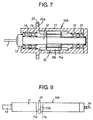
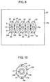
- a tool main spindle assembly 10a of the third embodiment is identical to the tool main spindle assembly 10 of the first embodiment except that a generally elliptical flange 33 is integrally formed to protrude from the outer peripheral surface of an intermediate portion of the housing 11 in radially opposed directions, namely, to protrude on diametrically opposed sides.
- the minor axis of the generally elliptical flange 33 is as long as the diameter of the housing 11.
- a pair of mounting holes 33a are formed in the flange 33.
- the tool main spindle assembly 10a is removably mounted to the frame member 25 by inserting the housing 11 through the insertion hole 25a and fastening the housing 11 with screws screwed into the mounting holes 33a of the flange 33.
- the construction of the fourth embodiment is identical to that of the first embodiment. Therefore, components of the fourth embodiment identical to those of the first embodiment are denoted by the same reference numerals and will not be described in detail.
- This embodiment dispenses with a separate holding plate 30 and thus further reduces the number of required parts.
- the flange 33 does not protrude from the outer peripheral surface of the housing 11.
- the tool main spindle assemblies 10a can be located close to one another to such an extent that the outer peripheral surfaces of the housings 11 come into direct contact with one another.
- the fourth embodiment makes it possible to handle a work whose processing locations are extremely close to one another.
- the amounts by which the tools T protrude from the frame member 25 are adjusted by preparing a plurality of different tool main spindle assemblies 10a with flanges 33 which are axially differently located with respect to the housings 11 and changing amounts by which the tools T protrude from the chucks 13.
- a flange 33 protruding from the outer peripheral surface of the housing 11 of the tool main spindle assembly 10a.
- the flange 33, the shape in the neighborhood of the flange 33, and the manner in which the tool main spindle assembly 10a is mounted to the frame member 25 are different from those of the fourth embodiment shown in Figs. 7 and 8.
- the housing 11 of the tool main spindle assembly 10a is in the shape of a circular cylinder.
- fitting surfaces 11a are formed on the outer peripheral surface of the flange 33 on axially opposed sides, and outer peripheral surfaces of the flange 33 located outwardly of the fitting surfaces 11a are slightly smaller in diameter than the fitting surfaces 11a.
- the fitting surfaces 11a are located with respect to the insertion holes 25a in a relation of clearance fit which is similar to transit fit.
- the flange 33 of the fifth embodiment is generally in the shape of a sexangle and has a pair of flat portions 33b.
- the flat portions 33b are parallel to each other and in contact with the fitting surface 11a as viewed in the axial direction.
- Mounting holes 33a are formed in portions of the flange 33 which protrude on diametrically opposed sides.
- a chuck 13 and a feeder line 18 for the built-in motor are provided at front and rear ends of the tool main spindle assembly 10a respectively.
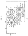
- three upper ones 10A 1 through 10A 3 of six tool main spindle assemblies 10A 1 through 10A 6 are mounted to the frame member 25 in the following manner. That is, the housings 11 are inserted into the insertion holes 25A of the frame members 25 from the side of side surfaces 25b opposed to a work (not shown), and the fitting surfaces 11a are fitted into the insertion holes 25a to be positioned therein. Then, the tool main spindle assemblies 10A 1 through 10A 3 are mounted to the frame member 25 by means of the mounting bolts 36 with the flanges 33 in close contact with the side surfaces 25b. In an example shown in Figs.
- the tool main spindle assemblies 10A 1 through 10A 3 are mounted such that the flat portions 33b of the flanges 33 are in close contact with one another. However, it is not obligatory that the flat portions 33b of the flanges 33 be in close contact with one another.
- the furthest left one 10A 4 shown in Fig. 11 is mounted to the frame member 25 in the following manner. That is, the housing 11 is inserted into the insertion hole 25A from the side of the other side surface 25c opposed to one side surface 25b, and the fitting surface 11A is fitted into the insertion hole 25a to be position therein. Then, the tool main spindle assembly 10A 4 is mounted to the frame member 25 by means of the mounting bolts 36 with the flange 33 in close contact with the other side surface 25c.
- the flanges 33 of the tool main spindle assemblies 10A 1 , 10A 2 are mounted to one side surface 25b of the frame member 25, the flange 33 of the tool main spindle assembly 10A 4 (indicated by a broken line) is mounted to the other side surface 25c. Therefore, the flanges 33 of the tool main spindle assemblies 10A 1 , 10A 2 do not interfere with the flange 33 of the tool main spindle assembly 10A 4 .
- the tool main spindle assemblies 10A 1 , 10A 2 and the tool main spindle assembly 10A 4 can be arranged in an overlapping manner with the frame member 25 interposed therebetween.
- the tool main spindle assembly 10A 4 can be located close to the tool main spindle assemblies 10A 1 , 10A 2 to such an extent that the outer peripheral surface of the housing 11 comes into close contact with the flanges 33 of the tool main spindle assemblies 10A 1 , 10A 2 (or to such an extent that the outer peripheral surfaces of the housings 11 of the tool main spindle assemblies 10A 1 , 10A 2 come into close contact with the flange 33 of the tool main spindle assembly 10A 4 ).
- the tool main spindle assembly 10A 4 can be located closer to the tool main spindle assemblies 10A 1 , 10A 2 in comparison with the case where the tool main spindle assemblies 10A 1 through 10A 6 are mounted to only one side surface 25b of the frame member 25.
- the fifth embodiment makes it possible to handle a work whose processing locations are close to one another.
- the other two lower tool main spindle assemblies 10A 5 , 10A 6 are smaller than the other ones.
- the tool main spindle assemblies 10A 1 through 10A 3 the tool main spindle assemblies 10A 5 , 10A 6 are mounted altogether to an intermediate block 37.
- the intermediate block 37 is mounted to one side surface 25b of the frame member 25 by means of mounting bolts 38.
- Arrangement of the tool main spindle assemblies 10A 1 through 10A 6 is determined by positions of the insertion holes 25a formed in the frame member 25.
- the amount by which the tools T protrude from the frame member 25 can be adjusted by changing a thickness of the intermediate block 37.
- a multiple spindle processing unit which can change processing locations of a work in accordance with a modification made to the work
- the present invention is intended to facilitate changes of design corresponding to the modification made to the work and reduce the number of parts to be replaced.
- a frame member which is guided and supported so as to be moved towards and away from a work
- insertion holes are formed at a plurality of locations corresponding to processing locations of the work.
- a main spindle having a front end portion where a chuck for mounting a tool is provided is coaxially journaled in a housing in the shape of a circular cylinder or a polygonal cylinder and is rotationally driven by a built-in motor.
- Each of the tool main spindle assemblies is mounted to the frame member with the housing inserted through the insertion hole.
- the tool main spindle assembly may be mounted to the frame member through a holding plate which is divided into a plurality of portions for securely sandwiching the housing or through a flange which is integrated with the housing and which protrudes radially.
Landscapes
- Engineering & Computer Science (AREA)
- Mechanical Engineering (AREA)
- Physics & Mathematics (AREA)
- Optics & Photonics (AREA)
- Turning (AREA)
Applications Claiming Priority (2)
| Application Number | Priority Date | Filing Date | Title |
|---|---|---|---|
| JP14213799 | 1999-05-21 | ||
| JP14213799A JP3518421B2 (ja) | 1998-09-30 | 1999-05-21 | 多軸加工装置 |
Publications (2)
| Publication Number | Publication Date |
|---|---|
| EP1055475A2 true EP1055475A2 (de) | 2000-11-29 |
| EP1055475A3 EP1055475A3 (de) | 2003-08-06 |
Family
ID=15308238
Family Applications (1)
| Application Number | Title | Priority Date | Filing Date |
|---|---|---|---|
| EP00110767A Withdrawn EP1055475A3 (de) | 1999-05-21 | 2000-05-19 | Mehrspindelwerkzeugmaschine |
Country Status (3)
| Country | Link |
|---|---|
| US (1) | US6412156B1 (de) |
| EP (1) | EP1055475A3 (de) |
| KR (1) | KR100671875B1 (de) |
Cited By (10)
| Publication number | Priority date | Publication date | Assignee | Title |
|---|---|---|---|---|
| EP1275456A1 (de) * | 2001-07-13 | 2003-01-15 | Luigi Reguzzi | Antriebseinheit für eine Mehrzahl von Spindeln |
| DE102007016694B4 (de) * | 2007-04-04 | 2009-12-03 | Edgar Klitsch | Bohraggregat mit ein- oder mehrreihigen ausstellbaren direkt angetriebenen Bohrspindeln |
| CZ301607B6 (cs) * | 2006-09-18 | 2010-04-28 | Tajmac-Zps, A. S. | Zarízení pro pohon vreten obrábecího stroje |
| WO2010139828A1 (es) * | 2009-06-05 | 2010-12-09 | Mecánica Comercial Meco, S.L. | Máquina de perforación con múltiples cabezales simultáneos |
| CN101954505A (zh) * | 2010-08-06 | 2011-01-26 | 广州杰赛科技股份有限公司 | 铣床横向跨轴进行成型加工的方法 |
| CN103639467A (zh) * | 2013-12-20 | 2014-03-19 | 江苏真绩机械制造有限公司 | 多轴专用钻床 |
| DE102014200291A1 (de) | 2013-01-10 | 2014-07-10 | Mecánica Comercial Meco, S.L. | Mehrkopf-Simultanbohrmaschine |
| DE102010022389B4 (de) * | 2009-09-14 | 2015-08-27 | Eichhorn Gmbh & Co. Kg | Vorrichtung und Verfahren zur Herstellung eines schallabsorbierenden Paneels und Paneel |
| CN110549243A (zh) * | 2019-09-25 | 2019-12-10 | 安徽博美奥齐机械设备有限公司 | 一种用于抛光机床的主轴升降装置 |
| DE102019104252B3 (de) * | 2019-02-20 | 2020-08-13 | Schaeffler Technologies AG & Co. KG | Linearaktuator und Baukasten zur Herstellung dieses Linearaktuators |
Families Citing this family (4)
| Publication number | Priority date | Publication date | Assignee | Title |
|---|---|---|---|---|
| EP1695791B1 (de) * | 2005-02-23 | 2007-12-05 | Alfing Kessler Sondermaschinen GmbH | Bearbeitungsmaschine mit mehreren parallelen Spindelanordnungen |
| KR101102711B1 (ko) * | 2009-12-18 | 2012-01-05 | 한국산업기술대학교산학협력단 | 사이드 폭 조절이 가능한 어린이 보호 시트 |
| FR3001645B1 (fr) * | 2013-02-06 | 2015-05-15 | Aircelle Sa | Tete de percage acoustique |
| JP7234136B2 (ja) * | 2017-12-22 | 2023-03-07 | シチズン時計株式会社 | 工具保持装置及び工作機械 |
Family Cites Families (20)
| Publication number | Priority date | Publication date | Assignee | Title |
|---|---|---|---|---|
| US3240084A (en) * | 1960-03-24 | 1966-03-15 | Bendix Corp | Apparatus for boring metal plates |
| DE1528088B1 (de) * | 1965-03-13 | 1969-09-18 | Scheer & Cie C F | Bohrvorrichtung,insbesondere zur Holzbearbeitung |
| US3546978A (en) * | 1969-10-23 | 1970-12-15 | Singer Co | Fluid pressure differential control system for actuation of a movable member |
| US3822958A (en) * | 1973-06-04 | 1974-07-09 | Ekstrom Carlson & Co | Multispindle drilling machine |
| SU670391A1 (ru) * | 1975-09-09 | 1979-06-30 | Предприятие П/Я А-1984 | Многошпиндельна головка дл обработки отверстий |
| DE2633660A1 (de) * | 1976-07-27 | 1978-02-02 | Sigloch & Schrieder | Mehrspindelbohrkopf |
| GB1575902A (en) * | 1977-06-13 | 1980-10-01 | Moseley Rubber Co Ltd | Method of and means for the piercing of holes in the coverings of suction rollers |
| JPS5521835A (en) | 1978-08-03 | 1980-02-16 | Toshiba Corp | Method and device of coating internal surface of cathode ray tube |
| US4198181A (en) * | 1978-09-25 | 1980-04-15 | Smelser James M | Apparatus for drilling holes in "H" beams |
| US4322990A (en) * | 1980-03-10 | 1982-04-06 | Erikson Tool Company | Device for setting end working tools of multiple spindle automatic bar machines |
| US4400120A (en) * | 1980-05-21 | 1983-08-23 | General Battery Corporation | Apparatus for removing temporary side terminals from batteries |
| US4419803A (en) * | 1981-02-04 | 1983-12-13 | Ashcombe Products Company | Method of forming a tool assembly |
| US4441245A (en) * | 1981-02-04 | 1984-04-10 | Ashcombe Products Company | Gang cutting tool assembly |
| JPS58102612A (ja) * | 1981-12-15 | 1983-06-18 | Seiwa Seiki Kk | マシニングセンタ用多軸ヘツド |
| DE3324809A1 (de) * | 1983-07-09 | 1985-01-17 | Dornier System Gmbh, 7990 Friedrichshafen | Verfahren zum vorbereiten einer holzimpraegnierung |
| JPS62166911A (ja) * | 1986-01-21 | 1987-07-23 | Honda Motor Co Ltd | 多軸回転工具ユニツト |
| US4869626A (en) * | 1986-04-18 | 1989-09-26 | Dynamotion Corporation | High speed drilling spindle |
| US4850754A (en) * | 1987-09-25 | 1989-07-25 | Ashcombe Products Company | Automatic drilling machine |
| US4917548A (en) * | 1988-04-04 | 1990-04-17 | Ruff Robert W | Pattern drilling machine for securing roofing insulation |
| FR2749201B1 (fr) * | 1996-06-04 | 1998-08-21 | Peugeot | Dispositif de reglage de la position d'une broche d'usinage ou analogue sur un support relativement a un element de reference de ce support |
-
2000
- 2000-05-19 US US09/574,260 patent/US6412156B1/en not_active Expired - Fee Related
- 2000-05-19 KR KR1020000027028A patent/KR100671875B1/ko not_active Expired - Fee Related
- 2000-05-19 EP EP00110767A patent/EP1055475A3/de not_active Withdrawn
Cited By (14)
| Publication number | Priority date | Publication date | Assignee | Title |
|---|---|---|---|---|
| EP1275456A1 (de) * | 2001-07-13 | 2003-01-15 | Luigi Reguzzi | Antriebseinheit für eine Mehrzahl von Spindeln |
| CZ301607B6 (cs) * | 2006-09-18 | 2010-04-28 | Tajmac-Zps, A. S. | Zarízení pro pohon vreten obrábecího stroje |
| DE102007016694B4 (de) * | 2007-04-04 | 2009-12-03 | Edgar Klitsch | Bohraggregat mit ein- oder mehrreihigen ausstellbaren direkt angetriebenen Bohrspindeln |
| WO2010139828A1 (es) * | 2009-06-05 | 2010-12-09 | Mecánica Comercial Meco, S.L. | Máquina de perforación con múltiples cabezales simultáneos |
| ES2351761A1 (es) * | 2009-06-05 | 2011-02-10 | Mecanica Comercial Meco, S.L. | Maquina de perforacion con multiples cabezales simultaneos. |
| DE102010022389B4 (de) * | 2009-09-14 | 2015-08-27 | Eichhorn Gmbh & Co. Kg | Vorrichtung und Verfahren zur Herstellung eines schallabsorbierenden Paneels und Paneel |
| CN101954505A (zh) * | 2010-08-06 | 2011-01-26 | 广州杰赛科技股份有限公司 | 铣床横向跨轴进行成型加工的方法 |
| DE102014200291A1 (de) | 2013-01-10 | 2014-07-10 | Mecánica Comercial Meco, S.L. | Mehrkopf-Simultanbohrmaschine |
| CN103639467A (zh) * | 2013-12-20 | 2014-03-19 | 江苏真绩机械制造有限公司 | 多轴专用钻床 |
| CN103639467B (zh) * | 2013-12-20 | 2015-09-16 | 江苏真绩机械制造有限公司 | 多轴专用钻床 |
| DE102019104252B3 (de) * | 2019-02-20 | 2020-08-13 | Schaeffler Technologies AG & Co. KG | Linearaktuator und Baukasten zur Herstellung dieses Linearaktuators |
| WO2020169133A1 (de) * | 2019-02-20 | 2020-08-27 | Schaeffler Technologies AG & Co. KG | Linearaktuator und baukasten zur herstellung dieses linearaktuator |
| CN110549243A (zh) * | 2019-09-25 | 2019-12-10 | 安徽博美奥齐机械设备有限公司 | 一种用于抛光机床的主轴升降装置 |
| CN110549243B (zh) * | 2019-09-25 | 2023-11-28 | 安徽博美奥齐机械设备有限公司 | 一种用于抛光机床的主轴升降装置 |
Also Published As
| Publication number | Publication date |
|---|---|
| US6412156B1 (en) | 2002-07-02 |
| KR20010020863A (ko) | 2001-03-15 |
| KR100671875B1 (ko) | 2007-01-19 |
| EP1055475A3 (de) | 2003-08-06 |
Similar Documents
| Publication | Publication Date | Title |
|---|---|---|
| US6412156B1 (en) | Multi-spindle machine tool | |
| JP4783511B2 (ja) | 転動体スクリュードライブ | |
| KR101734296B1 (ko) | 툴 홀더 | |
| US20050217095A1 (en) | Spindle head for a universal milling machine | |
| JP5308893B2 (ja) | 工作機械の刃物台 | |
| JPH04261739A (ja) | 工具保持装置 | |
| EP1671728B1 (de) | Werkzeugrevolver | |
| JPH10503433A (ja) | 割出し式ウェッジ及びインサートを備える複数方向ミリングカッタ | |
| CN101176928A (zh) | 电液伺服阀盖板的周向和轴向孔组合加工用钻模 | |
| JP7207917B2 (ja) | Nc円テーブル装置 | |
| JP3518421B2 (ja) | 多軸加工装置 | |
| CN217667698U (zh) | 360°防转带偏摆的复合拧紧机构 | |
| GB2305023A (en) | Stator core and housing for an alternator | |
| US7165922B2 (en) | Cutting tool assembly having construction enabling cutting tool to have large diameter | |
| KR20010047913A (ko) | 공작물 고정용 지그 | |
| CN223160501U (zh) | 一种用于普通车床的加工结构 | |
| CN218425667U (zh) | 一种汽车转向机壳体加工刀具 | |
| CN220087032U (zh) | 一种电机安装换向装置 | |
| CN224182151U (zh) | 铣刀及刀具组件 | |
| JPS5852039Y2 (ja) | 回転工具用ホルダ− | |
| CN219131596U (zh) | 平衡车电机轴工装夹具 | |
| CN223776096U (zh) | 一种刀具输出可转向角度铣头 | |
| JPS6343002Y2 (de) | ||
| JP5657341B2 (ja) | 工作機械 | |
| JP2025150023A (ja) | 工作機械 |
Legal Events
| Date | Code | Title | Description |
|---|---|---|---|
| PUAI | Public reference made under article 153(3) epc to a published international application that has entered the european phase |
Free format text: ORIGINAL CODE: 0009012 |
|
| AK | Designated contracting states |
Kind code of ref document: A2 Designated state(s): AT BE CH CY DE DK ES FI FR GB GR IE IT LI LU MC NL PT SE |
|
| AX | Request for extension of the european patent |
Free format text: AL;LT;LV;MK;RO;SI |
|
| PUAL | Search report despatched |
Free format text: ORIGINAL CODE: 0009013 |
|
| AK | Designated contracting states |
Designated state(s): AT BE CH CY DE DK ES FI FR GB GR IE IT LI LU MC NL PT SE |
|
| AX | Request for extension of the european patent |
Extension state: AL LT LV MK RO SI |
|
| RIC1 | Information provided on ipc code assigned before grant |
Ipc: 7B 23B 39/18 B Ipc: 7B 23Q 5/04 B Ipc: 7B 23Q 39/04 B Ipc: 7B 23B 39/20 B Ipc: 7B 23B 39/16 A |
|
| 17P | Request for examination filed |
Effective date: 20040121 |
|
| AKX | Designation fees paid |
Designated state(s): DE FR GB |
|
| 17Q | First examination report despatched |
Effective date: 20050309 |
|
| STAA | Information on the status of an ep patent application or granted ep patent |
Free format text: STATUS: THE APPLICATION IS DEEMED TO BE WITHDRAWN |
|
| 18D | Application deemed to be withdrawn |
Effective date: 20051213 |