EP1055484A2 - Axialverschiebungsmechanismus - Google Patents
Axialverschiebungsmechanismus Download PDFInfo
- Publication number
- EP1055484A2 EP1055484A2 EP00111297A EP00111297A EP1055484A2 EP 1055484 A2 EP1055484 A2 EP 1055484A2 EP 00111297 A EP00111297 A EP 00111297A EP 00111297 A EP00111297 A EP 00111297A EP 1055484 A2 EP1055484 A2 EP 1055484A2
- Authority
- EP
- European Patent Office
- Prior art keywords
- fixed portion
- turret
- axial displacement
- screw
- turret plate
- Prior art date
- Legal status (The legal status is an assumption and is not a legal conclusion. Google has not performed a legal analysis and makes no representation as to the accuracy of the status listed.)
- Withdrawn
Links
Images


Classifications
-
- B—PERFORMING OPERATIONS; TRANSPORTING
- B23—MACHINE TOOLS; METAL-WORKING NOT OTHERWISE PROVIDED FOR
- B23Q—DETAILS, COMPONENTS, OR ACCESSORIES FOR MACHINE TOOLS, e.g. ARRANGEMENTS FOR COPYING OR CONTROLLING; MACHINE TOOLS IN GENERAL CHARACTERISED BY THE CONSTRUCTION OF PARTICULAR DETAILS OR COMPONENTS; COMBINATIONS OR ASSOCIATIONS OF METAL-WORKING MACHINES, NOT DIRECTED TO A PARTICULAR RESULT
- B23Q39/00—Metal-working machines incorporating a plurality of sub-assemblies, each capable of performing a metal-working operation
- B23Q39/04—Metal-working machines incorporating a plurality of sub-assemblies, each capable of performing a metal-working operation the sub-assemblies being arranged to operate simultaneously at different stations, e.g. with an annular work-table moved in steps
- B23Q39/042—Metal-working machines incorporating a plurality of sub-assemblies, each capable of performing a metal-working operation the sub-assemblies being arranged to operate simultaneously at different stations, e.g. with an annular work-table moved in steps with circular arrangement of the sub-assemblies
- B23Q39/044—Metal-working machines incorporating a plurality of sub-assemblies, each capable of performing a metal-working operation the sub-assemblies being arranged to operate simultaneously at different stations, e.g. with an annular work-table moved in steps with circular arrangement of the sub-assemblies having at least one tool station cooperating with each work holder, e.g. multi-spindle lathes
-
- B—PERFORMING OPERATIONS; TRANSPORTING
- B23—MACHINE TOOLS; METAL-WORKING NOT OTHERWISE PROVIDED FOR
- B23Q—DETAILS, COMPONENTS, OR ACCESSORIES FOR MACHINE TOOLS, e.g. ARRANGEMENTS FOR COPYING OR CONTROLLING; MACHINE TOOLS IN GENERAL CHARACTERISED BY THE CONSTRUCTION OF PARTICULAR DETAILS OR COMPONENTS; COMBINATIONS OR ASSOCIATIONS OF METAL-WORKING MACHINES, NOT DIRECTED TO A PARTICULAR RESULT
- B23Q16/00—Equipment for precise positioning of tool or work into particular locations not otherwise provided for
- B23Q16/02—Indexing equipment
-
- Y—GENERAL TAGGING OF NEW TECHNOLOGICAL DEVELOPMENTS; GENERAL TAGGING OF CROSS-SECTIONAL TECHNOLOGIES SPANNING OVER SEVERAL SECTIONS OF THE IPC; TECHNICAL SUBJECTS COVERED BY FORMER USPC CROSS-REFERENCE ART COLLECTIONS [XRACs] AND DIGESTS
- Y10—TECHNICAL SUBJECTS COVERED BY FORMER USPC
- Y10T—TECHNICAL SUBJECTS COVERED BY FORMER US CLASSIFICATION
- Y10T74/00—Machine element or mechanism
- Y10T74/14—Rotary member or shaft indexing, e.g., tool or work turret
- Y10T74/1476—Rotary member or shaft indexing, e.g., tool or work turret with means to axially shift shaft
-
- Y—GENERAL TAGGING OF NEW TECHNOLOGICAL DEVELOPMENTS; GENERAL TAGGING OF CROSS-SECTIONAL TECHNOLOGIES SPANNING OVER SEVERAL SECTIONS OF THE IPC; TECHNICAL SUBJECTS COVERED BY FORMER USPC CROSS-REFERENCE ART COLLECTIONS [XRACs] AND DIGESTS
- Y10—TECHNICAL SUBJECTS COVERED BY FORMER USPC
- Y10T—TECHNICAL SUBJECTS COVERED BY FORMER US CLASSIFICATION
- Y10T74/00—Machine element or mechanism
- Y10T74/14—Rotary member or shaft indexing, e.g., tool or work turret
- Y10T74/1494—Locking means
Definitions
- This invention relates to an axial displacement mechanism, and more specifically to a axial displacement mechanism specifically adapted for a turret table for use in machinery for the automated manufacture of tin boxes.
- Automated tin box manufacture is accomplished by juxtaposing several different pieces of machinery and providing transfer means therebetween. Tin boxes can be manufactured in a vast number of different shapes and sizes and accordingly a single piece of machinery is required to be sufficiently versatile to enable manufacture of tin boxes in a large number of said shapes and sizes. It will be understood by those skilled in the art that the machinery used has a number of different components which can be exchanged to facilitate the manufacture of different boxes and currently the length of time taken to exchange all these various components to enable a particular set of machines to manufacture a different box shape can be up to an entire day.
- the invention hereinafter set forth, and also set forth in our co-pending applications have as their object the reduction of this time. Any reduction achievable in the "changeover" time is especially desirable when it is considered that tin box production rates using the machinery described hereinafter may reach 40 per minute.
- Tin boxes can contain a wide variety of different goods, such as bottles, chocolates, biscuits, tea, coffee and the like. Manufacturers of such products commonly consider the containment of their product in tins because of the rigidity and durability which the sheet steel, from which such tins are commonly made, provides. Additionally, the containment of a product in a tin box may also suggest that the product therein is of a certain quality, especially as ornate and detailed print effects can be obtained on the surface of the metal plates from which the tin boxes are manufactured. Such effects cannot be achieved, or are achieved only to a much lesser degree by the containment of products in cardboard cartons or receptacles of plastics materials. A tin box in which such a product is contained has the further advantage of being reusable to contain other household items such as screws, nuts bolts, pencils and pens, etc. after the product originally contained therein has been consumed or otherwise utilised.
- the first stage in the process of automated tin box manufacture is the profiling of a simple sheet steel, and generally rectangular, blank from which the walls of the tin box are ultimately constituted.
- the blank is fed through an "Automatic Notching, Curling and Beading" machine, referred to hereinafter as an ANCB machine.
- This machine consists of a plurality of consecutively driven rollers disposed both above and below the blank as it passes therebetween, each of said rollers performing a forming step on the blank.
- each blank as it exits the ANCB machine depends on the ultimate shape of the tin, but in general the blank is substantially flat with the exception of a hem provided parallel with one of the longer edges of the blank and proximate thereto, a bead is provided on one of said longer edges, a partial curl is provided around the alternate longer edge, and a pair of hooks oppositely disposed with respect to one another on the shorter edges.
- the ANCB machine has cutting means which notch the corners of the blank to preclude any interference effects which may be caused by said corners either when the blank is profiled and provided with the hooks along its shorter edges, when it is formed into the cross-sectional shape of the tin box, or when wrapped around and attached to the base of said tin box.
- the hem provides a surface behind which the beaded lip of a tin lid can engage to inhibit the removal of a lid separately formed and applied around the uppermost edge of the tin box, the bead is provided to hide the sharp longer edge of the blank which ultimately forms said uppermost edge of the tin box, the partial curl on the alternate longer edge of the blank is provided to facilitate the attachment of the blank, after same has been formed into the desired cross-sectional shape, to the base of the tin box, and the hooks provided along the shorter edges of the blank facilitate the connection of said edges to one another after the forming operation.
- the profiled blank is then fed from the ANCB machine into a bodymaker by a feed mechanism which generally comprises a pair of reciprocating feed bars whose motion is best described as being that of a "walking beam” in conjunction with “disappearing guides” which simultaneously urge the profiled blank towards and over a forming mandrel and precisely align said blank thereon.
- the disappearing guides are rotated away from the blank when it is held in contact with the uppermost portion of the mandrel, which is generally of similar shape to the desired cross-sectional shape of the tin box to be manufactured, by a mandrel clamping arrangement.
- the removal of the disappearing guides allows a pair of forming wings pivotally connected together and disposed above the mandrel to rotate about their pivot and form said blank, which is at this stage still substantially planar, around the said mandrel.
- the forming operation performed by the wings also constrains the oppositely disposed flanges on the shorter edges of the blank to interlock on the underside of the mandrel whereupon a second forming tool compresses the metal of the blank in the interlocked region to form the vertical seam within the wall of the tin box.
- the blank is clamped against the upper surface of said mandrel by said mandrel clamping arrangement.
- the bodymaker thus forms the walls of the tin box into the desired cross-sectional whereafter the hollow wall section is fed into the round and irregular seamer which seamingly attaches a base provided with a peripheral flange by simultaneously compressing and deforming said peripheral flange and the partial curl provided on one of the edges of the blank together to form a seam.
- the bodymaker is responsible for the formation of the hooks on the shorter edges of the blank to facilitate connection of said edges to one another.
- the seamer is conventionally juxtaposed with the bodymaker and an end feeder, these two pieces of machinery providing the body of the tin box and its base respectively which are connected together by the seamer.
- the seamer is also provided with a turret table which intermittently rotates, the intermittency dependent on the rate of production of tin boxes, the duration of the various forming steps throughout the production process, and the rate of infeed of blanks.
- This invention is specifically concerned with the provision of an axial displacement mechanism for the turret plate of the seamer which ensures precise angular orientation of said turret plate with respect to the various stations which said table serves, and also precise axial disposition with respect to each of these stations and to the seaming chuck of the seamer.
- the turret plates currently in use on seaming machines are generally circular or quadrangular and rotate periodically by approximately 90° every rotation and also always in the same direction.
- Said turret plates are provided with apertures and overlie a turret table which is rigidly secured to a frame which does not rotate.
- the surface of the turret table is generally smooth over its upper surface such that the hollow tubular portion of a partially complete tin box in contact therewith around one of its perimetral edges can slide unimpeded thereacross as the turret plate rotates above.
- the tubular portion stands vertically on said turret table and it is the free perimetral edge thereof to which a base is to be seamed in the seaming chuck.
- the turret plate provides support for said tubular base portion around the free perimetral edge thereof thus preventing the tubular portion from falling over as it moves over the turret table.
- a base for the tubular portion is supplied by an end feeder adjacent one of the four positions in which the turret table and plate are disposed during stepwise rotation of said turret plate.
- Said end feeder positions the substantially planar pre-formed base on the turret plate over one of the apertures thereof before the turret plate is rotated to the seaming station.
- the separation of the turret table which supports the tubular portion of the box and the turret plate is such that the uppermost, free perimetral edge of the tubular portion is marginally lower than the upper surface of the turret plate by which the planar base is supported, and accordingly said uppermost edge of the tubular portion is not in contact with the lower surface of the planar base.
- an actuation mechanism underneath the turret table urges the tubular portion upwardly such that its uppermost edge comes into contact with the planar base and lifts same above the upper surface of the turret plate.
- the upper region of the tubular portion stands proud of the turret plate to allow the seaming chuck to act around the uppermost edge and seam the planar base thereto.
- the tin box is allowed to drop back onto the turret table, and the turret plate again rotates to a station where either the tin box is filled or removed.
- Turret tables are usually rigidly secured to a supporting frame and do not rotate, whereas turret plates are commonly connected to a rotationally driven spindle by means of a taper lock bush.
- a taper lock bush Such connection consists of a frusto-conical member which is disposed in a hollow end of the spindle and which is expanded as a bolt is screwed therethrough. The bush engages the inner walls of the hollow portion of the spindle as it expands and so secures the turret plate thereto.
- Such means of connection of the turret plate to the spindle allows the turret plate to move with two degrees of freedom (i.e.
- the turret plate may be provided with key means to ensure correct angular orientation with respect to the turret table, it is essential to accurately fix the axial separation of the turret table and turret plate because the distance between the turret plate and the seaming chuck must be constant.
- the relative height of the seaming chuck with respect to the turret table can be altered by raising or lowering said seaming chuck, and therefore different heights of tubular portions to which a base is to be seamed can be accommodated, but precise axial positioning of the turret plate is required to ensure that when the tubular portion is raised, its uppermost perimetral edge stands proud of the upper surface of the turret plate by a uniform amount. It will be appreciated by those skilled in the art that the precise axial positioning of a turret plate secured to a drive shaft by a taper lock bush can be time consuming and prone to human error.
- an axial displacement and locking mechanism for a turret plate rotationally driven by a spindle to which said mechanism is rigidly secured or with which said mechanism is integral, said mechanism allowing for precise adjustment of angular and axial orientation of said turret plate, said mechanism comprising an axially fixed portion and an axially movable portion, said axially fixed portion comprising location means which are received in the movable portion and prevent same from rotating relative to the fixed portion, characterised by screw means which are provided with threads which engage corresponding threads in the axially movable portion such that rotation of the screw means causes the axially movable portion to rise or fall relative to the fixed portion on the location means.
- the screw means abut the fixed portion.
- said screw means also comprises secondary screw means which can be received in a threaded aperture within the fixed portion to lock said axially movable portion at a particular axial displacement relative to said fixed portion.
- the plate is connected to the axially movable portion.
- the axially movable portion comprises an annular bush the centre of which engages with the screw means and which is provided with a plurality of apertures to allow for connection of the plate with bolts or the like.
- the annular bush comprises spacer means which extend the overall height of the annular bush and allow for the connection of a plate at the uppermost extremity thereof.
- the axial displacement mechanism described above represents a significant advance of existing turret table/plate mechanisms because not only is the possibility of relative angular rotation between the turret plate, the turret table and the drive shaft precluded, there is provision for infinitesimal axial displacement of said plate without any requirement to support said plate during the adjustment.
- the plate is supported by the screw means which abut the fixed portion of the mechanism or the uppermost end of the drive shaft.
- axial adjustment is rendered simple, quick and effective.
- the capability for adding spacer elements into the mechanism construction increases the versatility of the mechanism as a whole and allows for a far greater range of tin box depths to be accommodated on the turret table.
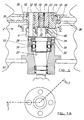
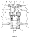
- an axial displacement and locking mechanism 2 having a fixed portion 4 provided with vertically disposed guide dowels, one of which is shown at 6 and which is received in an aperture, only marginally greater in diameter than the dowel itself, of a bush 10.
- the said bush is rigidly secured by bolts 14 to an axially movable portion 12 which has a central aperture 16 tapped with threads of a pitch which correspond to those threads on the external surface of a height adjustment screw 18.
- a locking screw 20 which serves to lock the axially movable portion 12 at a particular axial displacement relative to the fixed portion by being screwed into the upper surface of a rotationally driven spindle 22 thereof as shown in both Figure 1 and Figure 2.
- An annular resilient member 24 is disposed around the outside of said spindle 22 and within the fixed portion 4 and resiliently supports the axially movable portion 12 when proximate thereto.
- the spindle is enclosed by a bearing housing cover 32 secured to a cylindrical spindle sleeve 33 by bolts 34.
- An annular bearing assembly 35 is housed within said sleeve 33 and retained by said bearing housing cover 32.
- a turret table 36 is rigidly secured to the stationery frame, indicated generally at 37 and to which the cylindrical spindle sleeve 33 is also secured, the uppermost end of the spindle 22 which stands proud of the bearing housing cover 32 facilitating the connection of the fixed portion 4, to which the annular bush 10 is in turn connected.
- the turret table 36 remains stationery relative to the drive shaft 30, whereas a turret plate 38 is attached to said annular bush and rotates therewith.
- a locking screw 20 is unscrewed to a sufficient extent to be completely removed from the uppermost end of the spindle 22, whereupon the height adjustment screw 18 can be rotated.
- the rotational motion of the screw is converted into axially vertical movement of the axially movable portion 12.
- Said portion 12 slides vertically upwardly on the guide dowels 6 which prevent any angular rotation of either the axially movable portion 10 or the turret plate 38 connected thereto, and thus the angular orientation thereof is preserved with respect to the various stations which the turret plate may serve.
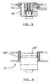
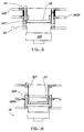
- FIG. 3-11 there is shown a number of differently configured mechanisms 50, 52, 54, 56, 58, 60, 62, 64, 66.
- the mechanisms 50, 52 shown in Figures 3, 4 are broadly identical to that shown in Figures 1 and 2, with the exception that in Figure 4, the annular bush is of an increased height compared to that shown in Figures 1-3.
- a composite annular bush element consisting of two separate parts 54X, 54Y is provided and together these serve to increase the starting displacement of a turret plate 54Z above the fixed portion 54A.
- the uppermost surface of the axially movable element is shown at 53, 55, 57, 59, 61, 63, 65, 67 respectively.
- annular bush elements 56X, 58X, 60X, 62X, 64X, 66X are shown enhanced by the addition of a spacer element 56Y, 58Y, 60Y 62Y, 64Y, 66Y thereto.
- a secondary turret plate may be provided, shown for example at 54XX, 56XX, 58XX, 60XX, 62XX, 64XX, 66XX which is provided with similar or identical apertures or cut-away portion to the uppermost turret plate provided in the embodiments shown in Figures 6-11.
- Said secondary turret plate provides additional lateral support for a hollow tubular box section retained within said apertures or cut-away portions. Such support decreases the likelihood of said tubular section falling over during movement thereof as it slides over the turret table which supports it.
- Turret tables are commonly used to support a workpiece such as the hollow tubular section of a tin box immediately prior to the seaming of a lid thereto and are commonly angularly indexed between a plurality, usually four, separate work stations disposed above the turret plate.
- the turret table is rigidly secured to a frame while the turret plate must be capable of being axially displaced relative thereto to suit a variety of different components.
- the turret plate is rigidly secured to an annular bush through a central aperture of which passes a cylindrical screw, the threads of which engage in corresponding threads in the inner annular surface of the bush.
- the screw abuts an axially fixed portion secured to or being a drive spindle which imparts motion to said fixed portion, said annular bush and said screw means to cause the turret plate to rotate.
- the provision of threads on the outside of the cylindrical screw and the abutment thereof with the spindle or fixed portion ensures that the rotation of the screw causes axial displacement of the annular bush and thus the turret plate relative to the turret table while the screw remains axially static.
- Guide means in the form of cylindrical pegs provided in the axially fixed portion are received through apertures in the annular bush to guide same and prevent angular displacement thereof as it is axially displaced.
- Locking means are provided to lock the screw to the spindle or other fixed portion to prevent unwanted rotation of same during rotation of the turret plate.
Landscapes
- Engineering & Computer Science (AREA)
- Mechanical Engineering (AREA)
- Specific Conveyance Elements (AREA)
- Machine Tool Units (AREA)
Applications Claiming Priority (2)
| Application Number | Priority Date | Filing Date | Title |
|---|---|---|---|
| GBGB9912268.1A GB9912268D0 (en) | 1999-05-27 | 1999-05-27 | Axial displacement mechanism |
| GB9912268 | 1999-05-27 |
Publications (2)
| Publication Number | Publication Date |
|---|---|
| EP1055484A2 true EP1055484A2 (de) | 2000-11-29 |
| EP1055484A3 EP1055484A3 (de) | 2002-01-16 |
Family
ID=10854215
Family Applications (1)
| Application Number | Title | Priority Date | Filing Date |
|---|---|---|---|
| EP00111297A Withdrawn EP1055484A3 (de) | 1999-05-27 | 2000-05-25 | Axialverschiebungsmechanismus |
Country Status (3)
| Country | Link |
|---|---|
| US (1) | US6427554B1 (de) |
| EP (1) | EP1055484A3 (de) |
| GB (1) | GB9912268D0 (de) |
Cited By (2)
| Publication number | Priority date | Publication date | Assignee | Title |
|---|---|---|---|---|
| CN106181442A (zh) * | 2016-08-19 | 2016-12-07 | 张德钊 | 一种运行稳定的工作台闩锁机构 |
| CN106271700A (zh) * | 2016-08-19 | 2017-01-04 | 张德钊 | 一种牢固的工作台闩锁装置 |
Family Cites Families (16)
| Publication number | Priority date | Publication date | Assignee | Title |
|---|---|---|---|---|
| US3628400A (en) * | 1970-04-13 | 1971-12-21 | Snyder Corp | Indexing turret |
| CH537231A (de) * | 1970-12-17 | 1973-05-31 | Buchmeier Heinz | Als Arbeitseinheit auf eine Werkzeugmaschine aufsetzbarer Revolverkopf |
| US3835516A (en) * | 1971-06-01 | 1974-09-17 | Warner Swasey Co | Machine tool with indexible tool support |
| US3877323A (en) * | 1973-01-09 | 1975-04-15 | Warner Swasey Co | Turret indexing machine |
| IT1037890B (it) * | 1975-05-06 | 1979-11-20 | Baruffaldi Frizioni Spa | Dispositivo per il posizionamento del corpo porta utensili in torrette automatiche per tornio o simile durante il movimento di rotazione del detto corpo per il passaggio da una posizione a quelle successive |
| CH595940A5 (de) * | 1975-12-18 | 1978-02-28 | Imoberdorf & Co | |
| US4128361A (en) * | 1977-05-23 | 1978-12-05 | Dresser Industries, Inc. | Locking means for positive feed drill |
| DE2741907A1 (de) * | 1977-09-17 | 1979-03-22 | Sauter Kg Feinmechanik | Schaltbarer mehrfachwerkzeughalter fuer werkzeugmaschinen, insbesondere drehmaschinen |
| IT1092860B (it) * | 1978-01-23 | 1985-07-12 | Baruffaldi Frizioni Spa | Torretta,porta-utensili con dispositivo ad azione elastica per il posizionamento del corpo porta-utensili |
| GB2081612B (en) * | 1980-08-08 | 1984-05-10 | Smt Machine Co Ab | Tool turret |
| DE3344805A1 (de) * | 1983-12-12 | 1985-06-13 | Expert Maschinenbau Gmbh, 6143 Lorsch | Hub-drehtisch-vorrichtung |
| DE3855228D1 (de) * | 1987-07-14 | 1996-05-30 | Baruffaldi Spa | Werkzeugrevolver mit einer epizykloiden Getriebe- und Positioniereinheit |
| DE3817937A1 (de) * | 1988-05-26 | 1989-11-30 | Sauter Kg Feinmechanik | Werkzeugrevolver |
| DE3929136C1 (de) * | 1989-09-01 | 1991-04-04 | Emag Maschinenfabrik Gmbh, 7335 Salach, De | |
| DE69031617T2 (de) * | 1989-09-27 | 1998-04-02 | Kamitsu Seisakusho Ltd | Garnaufwindeanordnung vom revolvertyp |
| DE19615335C1 (de) * | 1996-04-18 | 1997-10-02 | Gressel Ag | Spannvorrichtung mit mechanischem Kraftverstärker |
-
1999
- 1999-05-27 GB GBGB9912268.1A patent/GB9912268D0/en not_active Ceased
-
2000
- 2000-05-25 EP EP00111297A patent/EP1055484A3/de not_active Withdrawn
- 2000-05-27 US US09/580,737 patent/US6427554B1/en not_active Expired - Fee Related
Cited By (2)
| Publication number | Priority date | Publication date | Assignee | Title |
|---|---|---|---|---|
| CN106181442A (zh) * | 2016-08-19 | 2016-12-07 | 张德钊 | 一种运行稳定的工作台闩锁机构 |
| CN106271700A (zh) * | 2016-08-19 | 2017-01-04 | 张德钊 | 一种牢固的工作台闩锁装置 |
Also Published As
| Publication number | Publication date |
|---|---|
| EP1055484A3 (de) | 2002-01-16 |
| GB9912268D0 (en) | 1999-07-28 |
| US6427554B1 (en) | 2002-08-06 |
Similar Documents
| Publication | Publication Date | Title |
|---|---|---|
| US5775161A (en) | Staggered die method and apparatus for necking containers | |
| CA1277259C (en) | Drawn can body methods, apparatus and products | |
| US4058998A (en) | Containers | |
| EP1617960B1 (de) | Verfahren und vorrichtung zum umformen und reprofilieren eines unterteils eines behälters | |
| US4808053A (en) | Apparatus for making a necked-in container with a double seam on container cover | |
| US5209099A (en) | Draw-process methods, systems and tooling for fabricating one-piece can bodies | |
| US4503702A (en) | Tapered container and method and apparatus for forming same | |
| US5349837A (en) | Method and apparatus for processing containers | |
| AU2002239827A1 (en) | Method and apparatus for necking the open end of a container | |
| US3479931A (en) | Rotary dies | |
| US6427554B1 (en) | Axial displacement mechanism | |
| US4331014A (en) | Can beading apparatus | |
| US6481261B1 (en) | Feed mechanism | |
| US4183315A (en) | Method and apparatus for making a can end seam | |
| US5341667A (en) | Container bottom wall reforming apparatus and method | |
| JP7261228B2 (ja) | ロール縁部を形成する方法 | |
| US4856176A (en) | Process and apparatus for assembling a tubular container | |
| AU655754B2 (en) | Method and apparatus for processing containers | |
| US6497642B1 (en) | Mandrel and tooling replacement and apparatus therefor | |
| EP1050349A2 (de) | Spanndornanordnung | |
| EP1055469A2 (de) | Verstellmechanismus für ein Falzvorrichtung | |
| EP0017434A1 (de) | Dosenförmige Behälter sowie Verfahren und Vorrichtung zu deren Herstellung | |
| GB2350575A (en) | Forming mandrel | |
| EP0596016A1 (de) | Verfahren und vorrichtung zum reformieren von dosenboden zum verstärken der festigkeit. | |
| GB2147231A (en) | Turning over the edge of a sheet metal disc |
Legal Events
| Date | Code | Title | Description |
|---|---|---|---|
| PUAI | Public reference made under article 153(3) epc to a published international application that has entered the european phase |
Free format text: ORIGINAL CODE: 0009012 |
|
| AK | Designated contracting states |
Kind code of ref document: A2 Designated state(s): AT BE CH CY DE DK ES FI FR GB GR IE IT LI LU MC NL PT SE |
|
| AX | Request for extension of the european patent |
Free format text: AL;LT;LV;MK;RO;SI |
|
| PUAL | Search report despatched |
Free format text: ORIGINAL CODE: 0009013 |
|
| AK | Designated contracting states |
Kind code of ref document: A3 Designated state(s): AT BE CH CY DE DK ES FI FR GB GR IE IT LI LU MC NL PT SE |
|
| AX | Request for extension of the european patent |
Free format text: AL;LT;LV;MK;RO;SI |
|
| 17P | Request for examination filed |
Effective date: 20020701 |
|
| AKX | Designation fees paid |
Free format text: AT BE CH CY DE DK ES FI FR GB GR IE IT LI LU MC NL PT SE |
|
| GRAP | Despatch of communication of intention to grant a patent |
Free format text: ORIGINAL CODE: EPIDOSNIGR1 |
|
| STAA | Information on the status of an ep patent application or granted ep patent |
Free format text: STATUS: THE APPLICATION IS DEEMED TO BE WITHDRAWN |
|
| 18D | Application deemed to be withdrawn |
Effective date: 20040707 |