EP1055576A2 - Système de freinage électro-hydraulique et son procédé de commande - Google Patents
Système de freinage électro-hydraulique et son procédé de commande Download PDFInfo
- Publication number
- EP1055576A2 EP1055576A2 EP00108702A EP00108702A EP1055576A2 EP 1055576 A2 EP1055576 A2 EP 1055576A2 EP 00108702 A EP00108702 A EP 00108702A EP 00108702 A EP00108702 A EP 00108702A EP 1055576 A2 EP1055576 A2 EP 1055576A2
- Authority
- EP
- European Patent Office
- Prior art keywords
- temperature
- electro
- brake system
- pressure
- hydraulic
- Prior art date
- Legal status (The legal status is an assumption and is not a legal conclusion. Google has not performed a legal analysis and makes no representation as to the accuracy of the status listed.)
- Granted
Links
Images

Classifications
-
- B—PERFORMING OPERATIONS; TRANSPORTING
- B60—VEHICLES IN GENERAL
- B60T—VEHICLE BRAKE CONTROL SYSTEMS OR PARTS THEREOF; BRAKE CONTROL SYSTEMS OR PARTS THEREOF, IN GENERAL; ARRANGEMENT OF BRAKING ELEMENTS ON VEHICLES IN GENERAL; PORTABLE DEVICES FOR PREVENTING UNWANTED MOVEMENT OF VEHICLES; VEHICLE MODIFICATIONS TO FACILITATE COOLING OF BRAKES
- B60T8/00—Arrangements for adjusting wheel-braking force to meet varying vehicular or ground-surface conditions, e.g. limiting or varying distribution of braking force
- B60T8/32—Arrangements for adjusting wheel-braking force to meet varying vehicular or ground-surface conditions, e.g. limiting or varying distribution of braking force responsive to a speed condition, e.g. acceleration or deceleration
- B60T8/34—Arrangements for adjusting wheel-braking force to meet varying vehicular or ground-surface conditions, e.g. limiting or varying distribution of braking force responsive to a speed condition, e.g. acceleration or deceleration having a fluid pressure regulator responsive to a speed condition
- B60T8/40—Arrangements for adjusting wheel-braking force to meet varying vehicular or ground-surface conditions, e.g. limiting or varying distribution of braking force responsive to a speed condition, e.g. acceleration or deceleration having a fluid pressure regulator responsive to a speed condition comprising an additional fluid circuit including fluid pressurising means for modifying the pressure of the braking fluid, e.g. including wheel driven pumps for detecting a speed condition, or pumps which are controlled by means independent of the braking system
- B60T8/404—Control of the pump unit
-
- B—PERFORMING OPERATIONS; TRANSPORTING
- B60—VEHICLES IN GENERAL
- B60T—VEHICLE BRAKE CONTROL SYSTEMS OR PARTS THEREOF; BRAKE CONTROL SYSTEMS OR PARTS THEREOF, IN GENERAL; ARRANGEMENT OF BRAKING ELEMENTS ON VEHICLES IN GENERAL; PORTABLE DEVICES FOR PREVENTING UNWANTED MOVEMENT OF VEHICLES; VEHICLE MODIFICATIONS TO FACILITATE COOLING OF BRAKES
- B60T8/00—Arrangements for adjusting wheel-braking force to meet varying vehicular or ground-surface conditions, e.g. limiting or varying distribution of braking force
- B60T8/32—Arrangements for adjusting wheel-braking force to meet varying vehicular or ground-surface conditions, e.g. limiting or varying distribution of braking force responsive to a speed condition, e.g. acceleration or deceleration
- B60T8/34—Arrangements for adjusting wheel-braking force to meet varying vehicular or ground-surface conditions, e.g. limiting or varying distribution of braking force responsive to a speed condition, e.g. acceleration or deceleration having a fluid pressure regulator responsive to a speed condition
- B60T8/40—Arrangements for adjusting wheel-braking force to meet varying vehicular or ground-surface conditions, e.g. limiting or varying distribution of braking force responsive to a speed condition, e.g. acceleration or deceleration having a fluid pressure regulator responsive to a speed condition comprising an additional fluid circuit including fluid pressurising means for modifying the pressure of the braking fluid, e.g. including wheel driven pumps for detecting a speed condition, or pumps which are controlled by means independent of the braking system
- B60T8/4072—Systems in which a driver input signal is used as a control signal for the additional fluid circuit which is normally used for braking
- B60T8/4081—Systems with stroke simulating devices for driver input
- B60T8/4086—Systems with stroke simulating devices for driver input the stroke simulating device being connected to, or integrated in the driver input device
-
- B—PERFORMING OPERATIONS; TRANSPORTING
- B60—VEHICLES IN GENERAL
- B60T—VEHICLE BRAKE CONTROL SYSTEMS OR PARTS THEREOF; BRAKE CONTROL SYSTEMS OR PARTS THEREOF, IN GENERAL; ARRANGEMENT OF BRAKING ELEMENTS ON VEHICLES IN GENERAL; PORTABLE DEVICES FOR PREVENTING UNWANTED MOVEMENT OF VEHICLES; VEHICLE MODIFICATIONS TO FACILITATE COOLING OF BRAKES
- B60T2270/00—Further aspects of brake control systems not otherwise provided for
- B60T2270/82—Brake-by-Wire, EHB
-
- Y—GENERAL TAGGING OF NEW TECHNOLOGICAL DEVELOPMENTS; GENERAL TAGGING OF CROSS-SECTIONAL TECHNOLOGIES SPANNING OVER SEVERAL SECTIONS OF THE IPC; TECHNICAL SUBJECTS COVERED BY FORMER USPC CROSS-REFERENCE ART COLLECTIONS [XRACs] AND DIGESTS
- Y10—TECHNICAL SUBJECTS COVERED BY FORMER USPC
- Y10S—TECHNICAL SUBJECTS COVERED BY FORMER USPC CROSS-REFERENCE ART COLLECTIONS [XRACs] AND DIGESTS
- Y10S303/00—Fluid-pressure and analogous brake systems
- Y10S303/11—Accumulator
Definitions
- the present invention relates to an electrohydraulic Brake system according to the preamble of claim 1 and Method and a device for its control according to the Preambles of claims 3 and 18.
- DE 196 51 154 A1 describes a control method a brake system known, one of an electrical Motor operated pump is provided, the one and can be switched off, the run-on time of the pump after Switching off is determined and depends on the run-on time the control signals for braking force build-up or reduction Getting corrected. Using this method, a Estimated temperature of the braking system aimed. Electro-hydraulic brake systems, in which one Hydraulic fluid from a pressure accumulator Valve means controllable in the respective wheel brake cylinder are not the subject of this document.
- DE 196 04 126 A1 describes a method for controlling the Brake system of a vehicle known in which by at least one control signal with at least one variable parameter pressure is built up and / or reduced.
- the at least one parameter becomes dependent on at least one influencing the pressure change dynamics Corrected size.
- the influencing variable is in particular the temperature of the hydraulics or the ambient temperature called.
- the object of the invention is therefore to create a electro-hydraulic brake system, its functionality improved at both high and low temperatures is and the associated method and an apparatus to control the electro-hydraulic brake system.
- the means for detecting the expediently Temperature at least one temperature sensor. It turns out proved to be particularly advantageous, several To use temperature sensors, so that for example in A two-out-of-three selection as part of a safety assessment is feasible to the system regarding Temperature continues even if a temperature sensor fails operate and monitor. For example it is possible, provided as temperature sensors in pressure sensors To use temperature measuring elements. But also can Temperature sensors are also introduced.
- the inventive method are dependent on the detected temperature taking into account a sufficient functionality of the electrohydraulic Braking system heat-generating processes minimized.
- the Switching and isolating valves of the electro-hydraulic Brake system are energized for longer periods.
- the heat generated in the valves with the components in the Control unit leads to a steady increase in all Component temperatures.
- Temperature signal can now be determined that the Temperature exceeds limits, so that based on this information, all heat-producing processes in the Control device from the control device with regard to their Contribution to the total heat can be changed or minimized can, with increasing temperature functional Restrictions, always respecting a necessary one Basic brake function can be accepted.
- these measures can be taken at least partially the vehicle occupant, especially the Driver can be visualized. This means that for example, switching off certain heat-generating Processes or a reduced functionality of such Processes to the driver e.g. by a display device on Dashboard or other visualization device is shown.
- a preset temperature limit is exceeded in the Control unit can, for example, the following strategy or the associated measures are selected to a Overheating of the electrical and mechanical components (for example in one Control unit, i.e. one directly on one Hydraulic unit mounted control unit) to prevent: On the front axle can first switch to a back-up mode (a predefinable fallback level) so that no valves on the front axle are activated and on the rear axle has a pressure control with open Balance valves is carried out. In the case of another Rise in temperature may also fall to the full back-up fallback level be used until after receiving one corresponding lower temperature signal the electrohydraulic brake system again partially or can be switched on completely.
- a back-up mode a predefinable fallback level
- the pulse-pause ratio at one clocked control of a pump in electrohydraulic Braking system varies depending on the detected Temperature.
- the pump becomes one electrohydraulic brake system only fully activated, if the accumulator pressure is below a minimum braking value has sunk. Above this threshold the Pump usually operated clocked to the noise level to keep as low as possible. Exceptions to this regulation or Control strategies are traditionally just such Situations in which you can use the memory pressure history suggest a very large decrease in storage pressure can. At very low temperatures, however Delivery rate of the pump can be reduced such that a additional clocking at long accumulator pressure build-up times would lead, and thus the system availability at risk would.
- a pressure regulator of the electrohydraulic brake system which depends for example, driver requests or anti-lock braking system and / or Anti-skid control signals in the Wheel brake pressure regulates, tends at low Vibrating temperatures. This also affects the rest of the Braking effect and / or driving stability and / or the Regulations affecting vehicle safety. This Effect is based on the physically changed behavior of the Brake fluid at low temperatures.
- the invention temperature information regarding the electrohydraulic brake system, the Conversion of the control current into magnetic forces and thus the Pressure difference at the inlet control valve carried out more precisely be, so that a more accurate and reliable Storage pressure estimation is possible.
- the Current ramp slower in the presence of low temperatures be driven to the changed time behavior of the cold Take brake fluid into account. Overall, increases by considering the temperature of the electrohydraulic brake system the reliability of the Emergency operation.
- the sensed temperature is advantageously above also generally in the control of the pressure modulators respective wheel brake used.
- the sensed temperature is expediently used for Monitoring the charge and / or discharge of the Accumulator used.
- the Gradient of the pressure in the pressure accumulator to plausible Values monitored Conventionally, this must be allowed Plausibility band can be interpreted relatively broadly, as well low pressure gradients, which the pump at low To generate temperatures of for example about -30 ° in the Location is must be covered.
- the Temperature information can make this plausibility band strong be narrowed down so that more effective monitoring of the Charging the pressure accumulator is possible.
- the pump delivery rate should be so small that none Storage charging takes place.
- the electro-hydraulic brake system can be switched on as soon as a corresponding Temperature signal is obtained.
- the temporary backup system can thus reduce the functionality of a particular Fallback level, especially the fallback level with the Basic functions, control. But also several functional fallback levels through the temporary backup system managed and deployed.
- the temperature detected is also expediently at the pedal travel simulator (PWS) monitoring is taken into account.
- PWS pedal travel simulator
- the Pedal travel simulator monitoring checks the connection between the measured variables that express the driver's request.
- the sensed temperature is expediently used for a Monitoring the venting status of the fallback level used.
- the pressure accumulator is a wear or replacement part designed. The functionality of this memory must therefore be checked regularly. As a measure of the goodness of the The gas filling pressure can be used in the accumulator. This However, gas filling pressure is strongly temperature-dependent (e.g. 60 to 120 bar over a temperature range from -40 ° C to 120 ° C). Taking into account the temperature the system can take much more precise measurements be carried out and thus brought to the display, whether the pressure accumulator needs to be replaced.
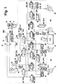
- Figure 1 shows a preferred embodiment of a electrohydraulic brake system.
- Figure 2 is a Procedure for changing between different control measures using different Temperature limits shown.
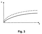
- Figure 3 shows for a special application, the pump control, a Relationship between pump speed and temperature.
- the electro-hydraulic brake system in Figure 1 shows one Master brake cylinder HBZ with reservoir 10 to which a Brake pedal operated by the driver is attached. Further a hydraulic unit 14 is provided, which valve and Pump arrangements for controlling the wheel brakes 16, 18, 20 and contains 22.
- a Brake pedal switch 24 With the brake pedal 12 is a Brake pedal switch 24 connected, which when the Brake pedal closes and a measuring device 26 for Detection of the brake pedal deflection.
- the Brake pedal switch 24 can be designed as a simple closer be, or to improve monitoring as double switch with one break and one make.
- a special design shows the brake pedal switch 24 as brake light switch BLS.
- the measuring device 26 for detecting the deflection S of the pedal 12 for Improvement can be designed redundantly.
- a Pedal travel simulator PWS provided, which for the driver Pressing the brake pedal 12 simulates a counterforce.
- On the main brake cylinder HBZ are the two brake circuits HZ1 and HZ2 connected. There is a separating valve in each of these MV_TVR or MV_TVL inserted, which for electrical controlled brake system is closed by energization.
- a pressure sensor 28 from the driver via the Brake pedal actuation applied pressure. When closed
- the main brake cylinder is hydraulically separated from the isolating valves Pressure control system disconnected.
- Pressure control system is for each wheel brake has a pressure modulator for brake pressure control contain.
- a pressure modulator consists of one Inlet valve (MV_UVR, MV_UVL, MV_UHR, MV_UHL), one each Exhaust valve (MV_DVR, MV_DVL, MV_DHR, MV_DHL) and one each Pressure sensor 30, 32, 34 and 36, which the pressure in the Wheel brake leading line measures.
- MV_UVR Inlet valve
- MV_UVL Inlet valve
- MV_UHR MV_UHR
- MV_UHL Exhaust valve
- MV_DVR MV_DVL
- MV_DHR MV_DHR
- MV_DHL Pressure sensor 30, 32, 34 and 36
- relief valves MV_EVA or MV_EHA are provided for each axis that are in the de-energized state the pressure reduction from the Allow wheel pressure modulators on one axis. You connect the Pressure modulators of an axis with those to the reservoir 10 leading return lines. In the electrically controlled Operating status, these two valves are permanent energized, d. H. closed. Furthermore, is a Temperature compensation valve MVTKVL and MVTKVR for everyone Front wheel pressure modulator provided. These valves are closed when deenergized and are used to reduce pressure from the Pressure modulator of a front wheel opened by energization, when certain conditions, especially a very long one Braking duration is present. The temperature compensation valves connect the brake line to the wheel brake with the Return line.
- the energy for brake pressure modulation comes from a pump driven by an electric motor 42, in particular a single-piston high-pressure pump. This is to a pressure accumulator 44, in particular one High-pressure accumulator, connected as an intermediate buffer serves and its pressure is detected by a pressure sensor 46 becomes.
- the pressure line of the pump 42 leads to the Inlet valves of the wheel brakes, while the suction line of the Pump 42 is connected to the reservoir 10.
- the relief valves MV_EVA and MV_EHA and the Temperature compensation valves MV_TKVL and MV_TKVR are not required in one embodiment. Because of the above Safety considerations here are six temperature sensors 100 to 105 shown.
- Temperature sensors can on the one hand as in the pressure sensors 30, 32, 34, 36 and 46 contained temperature measuring elements or on the other hand as separate temperature sensors can be designed.
- the number of Temperature sensors here is due to the two-out-of-three Security considerations set. Likewise, more or less, for example one pressure sensor per brake circuit, be used. A temperature estimate can also be used serve as the basis.
- a control unit 200 carries out the Control processes with regard to the electrohydraulic brake system. Because of There are only four inlets or outlets for clarity 201 shown schematically.
- the one described in FIG. 1 operates in normal operation Brake system as follows.
- the driver steps on the brake pedal. He feels a path-dependent counterforce. This Path dependence is determined by the defined characteristics of the Pedal travel simulator PWS formed.
- the Brake pedal switch 24 and / or the pressure sensor 28 are the Isolation valves (MV_TVR and MV_TVL) and the relief valves (MV_EVA and MV_EHA) closed.
- MV_TVR and MV_TVL the Isolation valves
- MV_EVA and MV_EHA the relief valves
- a pressure builds up, which results from the pedal force.
- the displacement sensor 26 and / or the pressure sensor 28 is the braking request of the Driver as a target deceleration or Target braking force calculated.
- the individual target wheel brake pressures formed. Depending on the driving condition and slip condition, these pressures are modified and via the wheel pressure modulators through valve energization adjusted. In a closed loop, everyone Wheel brake the current pressures on the wheel pressure sensors for the target-actual comparison is used. With different Target pressures in the left and right wheel of an axis the balance valves (MV_BVA and MV_BHA) closed and in the preset target pressure for each wheel brake by activation the intake and exhaust valves in the sense of a regulation of Actual brake pressure adjusted to the target brake pressure. To the Pressure build-up on a wheel brake becomes the inlet valve energized that the desired pressure is in the Training wheel brake with the desired dynamics.
- a Decrease in pressure is accordingly by energizing the Exhaust valve reached, with brake fluid in the Storage tank flows back via the return line.
- the Relief valves are used in the event of a fault in the system Effect. If the electrical system during braking fails, all valves fall into their de-energized state back. The relief valves then open the Pressure modulators to the return line so that no brake pressure can be locked up. These valves also allow in Idle state the volume compensation to the container Temperature fluctuations. This relapse of the valves in their de-energized state when the electrical fails Systems during braking and the one deployed on it The functionality of the relief valves thus corresponds to full-back-up fallout already mentioned above, at which still has a hydraulic-mechanical basic brake function is performed.
- control processes described are can be carried out by means of a control unit 200.
- the clarity are connecting lines, which the Control unit with the individual components to be controlled connect electro-hydraulic brake system, only drawn in on the control unit side and overall with 201 designated.
- 100 to 105 are the temperature sensors denotes the temperature of the hydraulic fluid or record brake fluid as mentioned above and send it to the Transfer control unit 200.
- the control unit Control or monitoring processes as in the Introduction to the description have been described, feasible. It it is also conceivable to switch the temperature signals on further control device, which with the control device 200 in Active connection is to be transferred.
- Temperature sensors there are six Temperature sensors shown. With this number of Sensors, a good safety assessment is possible (e.g. two-out-of-three selection per brake circuit, i.e. a sensor signal will match three sensors if two sensors match classified as correct), so that the electro-hydraulic Brake system even if a sensor fails in the manner according to the invention can be operated and monitored further is.
- the cable lengths to the temperature sensors are selected and set based on the graphic representation no functional connection.
- temperature sensors that directly the Hydraulic fluid temperature or Sensors can also measure the brake fluid temperature are used, which z. B. due to Component temperatures, such as the valves that Temperature of the electro-hydraulic brake system or Detect or determine the hydraulic unit.
- FIG. 2 shows a method in the form of a flow chart, in which the temperature information is evaluated.
- the temperature is recorded or estimated.
- a start as well Termination condition of the procedure localized.
- a Start condition can be, for example, the actuation of the Start switch of the vehicle and thus the generation of a Start signal. Another press to switch off would then correspond to a possible termination condition.
- After switching off it could also work for you maintain the procedure for a certain period of time be, for example, a subsequent valve test or perform other system checks.
- Query 301 It is now queried whether the temperature T is below a first limit value TG1.
- the measures M are used to control the electrohydraulic brake system used or changed. They relate, among other things, to those previously carried out and areas of application mentioned in the claims with regard to Control or regulation of the electro-hydraulic Braking system.
- a special embodiment of this is the use the temperature in relation to the pump speed.
- the degree of filling of the pump element or the pump 42 depends on the Viscosity of the brake fluid.
- the viscosity of the Brake fluid strongly depends on the temperature.
- Will the Pump 42 operated at a speed nopt at which the Filling level of the pump is optimally large this increases the Pump output. This output is higher as if the pump were at full speed of the pump motor and low temperature would hardly be filled. So is the Speed of the pump motor adjusted over the temperature, that the degree of filling of the pump is optimally large increases this the delivery rate of the pump.
- the Pump speed n can be increased linearly with temperature T.
- Another connection that is rather relevant in practice between pump speed n and temperature T the Pump speed in principle with increasing temperature also rise, but the curve that emerges shows one lower gradient towards higher temperatures. Consequently this curve is not linear but in another functional relationship, such as that in Figure 3 shown.
- the dashed curve shows an increased Delivery rate by increasing the speed compared to solid curve. This can take place in Figure 2 the use of individual temperature ranges Temperature limits TG the relationship also over a such a characteristic curve or a map are produced.
Landscapes
- Physics & Mathematics (AREA)
- Fluid Mechanics (AREA)
- Engineering & Computer Science (AREA)
- Transportation (AREA)
- Mechanical Engineering (AREA)
- Regulating Braking Force (AREA)
- Valves And Accessory Devices For Braking Systems (AREA)
Applications Claiming Priority (2)
| Application Number | Priority Date | Filing Date | Title |
|---|---|---|---|
| DE19923689A DE19923689A1 (de) | 1999-05-22 | 1999-05-22 | Elektrohydraulisches Bremssystem und Verfahren zu seiner Steuerung |
| DE19923689 | 1999-05-22 |
Publications (3)
| Publication Number | Publication Date |
|---|---|
| EP1055576A2 true EP1055576A2 (fr) | 2000-11-29 |
| EP1055576A3 EP1055576A3 (fr) | 2002-07-10 |
| EP1055576B1 EP1055576B1 (fr) | 2005-05-18 |
Family
ID=7908968
Family Applications (1)
| Application Number | Title | Priority Date | Filing Date |
|---|---|---|---|
| EP00108702A Expired - Lifetime EP1055576B1 (fr) | 1999-05-22 | 2000-04-22 | Système de freinage électro-hydraulique et son procédé de commande |
Country Status (4)
| Country | Link |
|---|---|
| US (1) | US6945613B1 (fr) |
| EP (1) | EP1055576B1 (fr) |
| JP (1) | JP4562860B2 (fr) |
| DE (2) | DE19923689A1 (fr) |
Cited By (1)
| Publication number | Priority date | Publication date | Assignee | Title |
|---|---|---|---|---|
| WO2002026540A1 (fr) * | 2000-09-27 | 2002-04-04 | Continental Teves Ag & Co. Ohg | Procede et systeme de regulation pour la commande d'un systeme d'actionnement de freinage a regulation electronique |
Families Citing this family (11)
| Publication number | Priority date | Publication date | Assignee | Title |
|---|---|---|---|---|
| WO2003053756A1 (fr) * | 2001-12-20 | 2003-07-03 | Continental Teves Ag & Co. Ohg | Procede et dispositif de controle d'un systeme de freinage |
| US6821096B2 (en) * | 2002-08-30 | 2004-11-23 | Illinois Tool Works Inc. | Multiple component metering and dispensing system |
| DE10349664B4 (de) * | 2003-10-24 | 2013-04-25 | Audi Ag | Hydraulische Bremsanlage für Kraftfahrzeuge |
| JP4525301B2 (ja) * | 2004-11-04 | 2010-08-18 | トヨタ自動車株式会社 | ブレーキ装置 |
| DE102005051712A1 (de) * | 2005-10-28 | 2007-05-03 | Bayerische Motoren Werke Ag | Betriebsverfahren für eine Fahrzeug-Bremsanlage |
| DE102005060324B4 (de) | 2005-12-16 | 2021-03-18 | Robert Bosch Gmbh | Erfassung des Verschleißes einer Motoransteuerung |
| ITBO20120233A1 (it) * | 2012-04-27 | 2013-10-28 | Magneti Marelli Spa | Servocomando idraulico di un cambio servocomandato |
| DE102018110781B4 (de) * | 2018-05-04 | 2021-02-25 | Solvo GmbH | Elektrohydraulisches Bremssystem und Verfahren zu dessen Betrieb |
| DE102018130678A1 (de) * | 2018-12-03 | 2020-06-04 | Wabco Gmbh | Elektrohydraulische Bremsanlage eines Off-Highway-Fahrzeugs |
| DE102020209749A1 (de) * | 2020-08-03 | 2022-02-03 | Robert Bosch Gesellschaft mit beschränkter Haftung | Verfahren zum Betreiben einer Rückförderpumpe einer Bremsanlage, Steuergerät, Bremsanlage |
| CN112377544B (zh) * | 2020-11-20 | 2022-02-15 | 徐州徐工矿业机械有限公司 | 全工况自动调节的电液比例湿盘制动冷却系统及控制方法 |
Citations (2)
| Publication number | Priority date | Publication date | Assignee | Title |
|---|---|---|---|---|
| DE19651154A1 (de) | 1995-12-16 | 1997-06-19 | Bosch Gmbh Robert | Verfahren und Vorrichtung zur Steuerung einer Bremsanlage |
| DE19604126A1 (de) | 1996-02-06 | 1997-08-07 | Bosch Gmbh Robert | Verfahren und Vorrichtung zur Steuerung der Bremsanlage eines Fahrzeugs |
Family Cites Families (24)
| Publication number | Priority date | Publication date | Assignee | Title |
|---|---|---|---|---|
| JPS57110548A (en) * | 1980-12-27 | 1982-07-09 | Komatsu Ltd | Automatic controlling device of retarder brake |
| US4671576A (en) * | 1985-03-06 | 1987-06-09 | Wabco Westinghouse (Railway Brake) (Pty.) Ltd. | Deceleration control system |
| DE3639664C2 (de) * | 1986-11-20 | 1995-10-19 | Teves Gmbh Alfred | Verfahren und Vorrichtung zur Überwachung des Zustandes oder der Beschaffenheit einer hydraulischen Flüssigkeit |
| JPH0652210B2 (ja) * | 1987-08-26 | 1994-07-06 | 宣行 杉村 | アキユムレ−タのガス封入圧力測定方法 |
| DE3729183C2 (de) * | 1987-09-01 | 1994-11-10 | Rexroth Mannesmann Gmbh | Schaltung zum Betrieb eines magnetisch betätigten Ventils |
| JPH02120111A (ja) * | 1988-10-28 | 1990-05-08 | Nissan Motor Co Ltd | 車両用圧力供給装置 |
| JP3066050B2 (ja) * | 1990-04-05 | 2000-07-17 | 東芝機械株式会社 | 油圧作業回路 |
| JPH06312655A (ja) * | 1993-04-28 | 1994-11-08 | Fuji Heavy Ind Ltd | 自動ブレーキ装置の制御方法 |
| DE19527805C2 (de) * | 1994-07-29 | 2000-11-23 | Toyota Motor Co Ltd | Brems-Steuervorrichtung, die in der Lage ist, eine Traktions-Kontrolle eines Fahrzeug-Antriebsrades durchzuführen und die eine Einrichtung zur Reduzierung des Zufuhrdruckes der Pumpe während der Traktions-Kontrolle aufweist |
| JPH0858553A (ja) * | 1994-08-26 | 1996-03-05 | Nippondenso Co Ltd | 車両用ブレーキ圧力制御装置 |
| JPH08207726A (ja) * | 1995-01-31 | 1996-08-13 | Mazda Motor Corp | 車両の制動力制御装置 |
| DE19513128A1 (de) * | 1995-04-07 | 1996-10-10 | Teves Gmbh Alfred | Verfahren zur temperaturabhängigen Einschaltung einer Druckmittel-Zusatzquelle in schlupfgeregelten Kraftfahrzeug-Bremsanlagen |
| US5941612A (en) * | 1996-05-17 | 1999-08-24 | Kelsey-Hayes Company | Method and apparatus for testing an ABS electronic control unit microprocessor |
| JPH1071944A (ja) * | 1996-06-24 | 1998-03-17 | Toyota Motor Corp | 制動力制御装置 |
| JPH1035462A (ja) * | 1996-07-29 | 1998-02-10 | Toyota Motor Corp | 車両用加速スリップ制御装置 |
| DE19713561C1 (de) * | 1997-04-02 | 1998-05-07 | Continental Ag | Elektrisches Bremssystem für ein Kraftfahrzeug und Verfahren zum Betreiben eines elektrischen Bremssystems für ein Kraftfahrzeug |
| JPH10278771A (ja) * | 1997-04-02 | 1998-10-20 | Toyota Motor Corp | 制動液圧制御装置 |
| DE19729097B4 (de) * | 1997-07-08 | 2006-07-20 | Robert Bosch Gmbh | Verfahren und Vorrichtung zur Steuerung einer Bremsanlage |
| JP3915209B2 (ja) * | 1997-12-03 | 2007-05-16 | 住友電気工業株式会社 | ブレーキ液温の検出方法及びブレーキ液圧の制御方法 |
| DE19807368A1 (de) * | 1998-02-21 | 1999-08-26 | Bosch Gmbh Robert | Verfahren und Vorrichtung zur Steuerung einer Bremsanlage |
| DE19843861A1 (de) * | 1998-09-25 | 2000-04-27 | Bosch Gmbh Robert | Verfahren und System zur Steuerung und/oder Regelung von Betriebsabläufen bei einem Kraftfahrzeug |
| US6030314A (en) * | 1998-09-28 | 2000-02-29 | Caterpillar Inc. | Method and apparatus for retarding a work machine having a fluid-cooled brake system |
| US6145939A (en) * | 1998-10-22 | 2000-11-14 | General Motors Corporation | Electro-hydraulic braking system having cold temperature detection and compensation |
| WO2000055022A1 (fr) * | 1999-03-17 | 2000-09-21 | Continental Teves Ag & Co. Ohg | Procede permettant de determiner des parametres |
-
1999
- 1999-05-22 DE DE19923689A patent/DE19923689A1/de not_active Ceased
-
2000
- 2000-04-22 EP EP00108702A patent/EP1055576B1/fr not_active Expired - Lifetime
- 2000-04-22 DE DE50010328T patent/DE50010328D1/de not_active Expired - Lifetime
- 2000-05-22 JP JP2000149905A patent/JP4562860B2/ja not_active Expired - Lifetime
- 2000-05-22 US US09/576,582 patent/US6945613B1/en not_active Expired - Lifetime
Patent Citations (2)
| Publication number | Priority date | Publication date | Assignee | Title |
|---|---|---|---|---|
| DE19651154A1 (de) | 1995-12-16 | 1997-06-19 | Bosch Gmbh Robert | Verfahren und Vorrichtung zur Steuerung einer Bremsanlage |
| DE19604126A1 (de) | 1996-02-06 | 1997-08-07 | Bosch Gmbh Robert | Verfahren und Vorrichtung zur Steuerung der Bremsanlage eines Fahrzeugs |
Cited By (2)
| Publication number | Priority date | Publication date | Assignee | Title |
|---|---|---|---|---|
| WO2002026540A1 (fr) * | 2000-09-27 | 2002-04-04 | Continental Teves Ag & Co. Ohg | Procede et systeme de regulation pour la commande d'un systeme d'actionnement de freinage a regulation electronique |
| US6851764B2 (en) | 2000-09-27 | 2005-02-08 | Continental Teves Ag & Co., Ohg | Method and control system for controlling an electronically regulated brake actuating system |
Also Published As
| Publication number | Publication date |
|---|---|
| JP4562860B2 (ja) | 2010-10-13 |
| EP1055576A3 (fr) | 2002-07-10 |
| DE50010328D1 (de) | 2005-06-23 |
| US6945613B1 (en) | 2005-09-20 |
| EP1055576B1 (fr) | 2005-05-18 |
| DE19923689A1 (de) | 2000-11-23 |
| JP2000344073A (ja) | 2000-12-12 |
Similar Documents
| Publication | Publication Date | Title |
|---|---|---|
| EP2822825B1 (fr) | Procédé de fonctionnement d'un système de freinage et appareil de freinage correspondant | |
| EP2809559B1 (fr) | Procede pour faire fonctionner un systeme de freinage de vehicules à moteur et systeme de freinage | |
| EP2822824B1 (fr) | Procede de fonctionnement d'un systeme de freinage de vehicules automobiles, et systeme de freinage | |
| EP3271227B1 (fr) | Système de freinage équipé d'une unité à maître-cylindre de frein à régulation mux innovante (mux 2.0) comprenant au moins une soupape de sortie, et procédé servant à la régulation de pression | |
| EP0868334B1 (fr) | Procede et dispositif pour commander la pompe d'un systeme de freinage electrohydraulique | |
| EP0937617B1 (fr) | Procédé et dispositif pour contrôler un système de freinage | |
| EP0937618B1 (fr) | Procédé et dispositif pour contrôler la fonction d'un système de freinage | |
| DE102015106089A1 (de) | Diagnoseverfahren für ein Bremssystem | |
| DE19828553C1 (de) | Verfahren und Vorrichtungen zur Durchführung eines Verfahrens zur Bildung oder Anpassung eines Ansteuersignals zur Ansteuerung eines ein Druckmedium fördernden Mittels eines Fahrzeugbremssystems | |
| EP1045786B1 (fr) | Procede et systeme de commande et/ou de reglage de sequences de fonctionnement d'un vehicule automobile | |
| EP2934968A1 (fr) | Système de freinage électrohydraulique pour véhicule et procédé de fonctionnement | |
| EP1324906A1 (fr) | Procede et systeme de regulation pour la commande d'un systeme d'actionnement de freinage a regulation electronique | |
| DE19729097B4 (de) | Verfahren und Vorrichtung zur Steuerung einer Bremsanlage | |
| EP1055576B1 (fr) | Système de freinage électro-hydraulique et son procédé de commande | |
| DE19914400A1 (de) | Verfahren und Vorrichtung zur Kompensation des Speicherdrucks in einem elektrohydraulischen Bremssystem | |
| DE10343985B4 (de) | Verfahren zur Verhinderung des Wegrollens an einer Steigung | |
| DE19954078B4 (de) | Bremssteuerungsvorrichtung eines Fahrzeugs | |
| DE102008036607A1 (de) | Verfahren und Vorrichtung zur hydraulischen Bremsdruckverstärkung | |
| DE10257839B4 (de) | Überwachung von Radbremsen | |
| WO2002066306A1 (fr) | Procede de commande d'un dispositif de freinage dans un vehicule automobile et dispositif de freinage | |
| EP1931548A1 (fr) | Procede pour faire fonctionner un systeme de freinage pour vehicules automobiles | |
| DE10142040A1 (de) | Verfahren und Regelsystem zur Ansteuerung eines elektronisch regelbaren Bremsbetätigungssystems | |
| DE102013203672A1 (de) | Dynamische Zeitsteuerung von Bremsregelsystemen mit Multiplex-Betrieb | |
| DE102021211245A1 (de) | Radbremsen Differenzdruckregelung | |
| EP1419073A1 (fr) | Procede pour ameliorer les caracteristiques de regulation d'un systeme d'antipatinage |
Legal Events
| Date | Code | Title | Description |
|---|---|---|---|
| PUAI | Public reference made under article 153(3) epc to a published international application that has entered the european phase |
Free format text: ORIGINAL CODE: 0009012 |
|
| AK | Designated contracting states |
Kind code of ref document: A2 Designated state(s): AT BE CH CY DE DK ES FI FR GB GR IE IT LI LU MC NL PT SE |
|
| AX | Request for extension of the european patent |
Free format text: AL;LT;LV;MK;RO;SI |
|
| PUAL | Search report despatched |
Free format text: ORIGINAL CODE: 0009013 |
|
| AK | Designated contracting states |
Kind code of ref document: A3 Designated state(s): AT BE CH CY DE DK ES FI FR GB GR IE IT LI LU MC NL PT SE |
|
| AX | Request for extension of the european patent |
Free format text: AL;LT;LV;MK;RO;SI |
|
| RIC1 | Information provided on ipc code assigned before grant |
Free format text: 7B 60T 8/40 A, 7B 60T 13/68 B, 7B 60T 17/22 B |
|
| 17P | Request for examination filed |
Effective date: 20030110 |
|
| AKX | Designation fees paid |
Designated state(s): DE FR GB |
|
| 17Q | First examination report despatched |
Effective date: 20030224 |
|
| GRAP | Despatch of communication of intention to grant a patent |
Free format text: ORIGINAL CODE: EPIDOSNIGR1 |
|
| GRAA | (expected) grant |
Free format text: ORIGINAL CODE: 0009210 |
|
| GRAS | Grant fee paid |
Free format text: ORIGINAL CODE: EPIDOSNIGR3 |
|
| AK | Designated contracting states |
Kind code of ref document: B1 Designated state(s): DE FR GB |
|
| REG | Reference to a national code |
Ref country code: GB Ref legal event code: FG4D Free format text: NOT ENGLISH |
|
| REG | Reference to a national code |
Ref country code: IE Ref legal event code: FG4D Free format text: LANGUAGE OF EP DOCUMENT: GERMAN |
|
| REF | Corresponds to: |
Ref document number: 50010328 Country of ref document: DE Date of ref document: 20050623 Kind code of ref document: P |
|
| GBT | Gb: translation of ep patent filed (gb section 77(6)(a)/1977) |
Effective date: 20050912 |
|
| PLBE | No opposition filed within time limit |
Free format text: ORIGINAL CODE: 0009261 |
|
| STAA | Information on the status of an ep patent application or granted ep patent |
Free format text: STATUS: NO OPPOSITION FILED WITHIN TIME LIMIT |
|
| ET | Fr: translation filed | ||
| 26N | No opposition filed |
Effective date: 20060221 |
|
| PGFP | Annual fee paid to national office [announced via postgrant information from national office to epo] |
Ref country code: GB Payment date: 20130422 Year of fee payment: 14 |
|
| PGFP | Annual fee paid to national office [announced via postgrant information from national office to epo] |
Ref country code: FR Payment date: 20130523 Year of fee payment: 14 |
|
| GBPC | Gb: european patent ceased through non-payment of renewal fee |
Effective date: 20140422 |
|
| REG | Reference to a national code |
Ref country code: FR Ref legal event code: ST Effective date: 20141231 |
|
| PG25 | Lapsed in a contracting state [announced via postgrant information from national office to epo] |
Ref country code: GB Free format text: LAPSE BECAUSE OF NON-PAYMENT OF DUE FEES Effective date: 20140422 |
|
| PG25 | Lapsed in a contracting state [announced via postgrant information from national office to epo] |
Ref country code: FR Free format text: LAPSE BECAUSE OF NON-PAYMENT OF DUE FEES Effective date: 20140430 |
|
| PGFP | Annual fee paid to national office [announced via postgrant information from national office to epo] |
Ref country code: DE Payment date: 20190627 Year of fee payment: 20 |