EP1055602A2 - Rückspannvorrichtung für Umreifungsmaschinen - Google Patents
Rückspannvorrichtung für Umreifungsmaschinen Download PDFInfo
- Publication number
- EP1055602A2 EP1055602A2 EP00107627A EP00107627A EP1055602A2 EP 1055602 A2 EP1055602 A2 EP 1055602A2 EP 00107627 A EP00107627 A EP 00107627A EP 00107627 A EP00107627 A EP 00107627A EP 1055602 A2 EP1055602 A2 EP 1055602A2
- Authority
- EP
- European Patent Office
- Prior art keywords
- roller
- swivel
- strapping
- force
- tensioning
- Prior art date
- Legal status (The legal status is an assumption and is not a legal conclusion. Google has not performed a legal analysis and makes no representation as to the accuracy of the status listed.)
- Granted
Links
- 238000000034 method Methods 0.000 claims abstract description 12
- 238000003780 insertion Methods 0.000 claims description 2
- 230000037431 insertion Effects 0.000 claims description 2
- 238000010408 sweeping Methods 0.000 claims 1
- 235000004443 Ricinus communis Nutrition 0.000 abstract description 5
- 230000001419 dependent effect Effects 0.000 description 3
- 238000003466 welding Methods 0.000 description 3
- 230000006835 compression Effects 0.000 description 2
- 238000007906 compression Methods 0.000 description 2
- 238000011065 in-situ storage Methods 0.000 description 2
- 230000003213 activating effect Effects 0.000 description 1
- 238000013459 approach Methods 0.000 description 1
- 230000012447 hatching Effects 0.000 description 1
- 238000004806 packaging method and process Methods 0.000 description 1
- 230000001105 regulatory effect Effects 0.000 description 1
- 238000005096 rolling process Methods 0.000 description 1
Images
Classifications
-
- B—PERFORMING OPERATIONS; TRANSPORTING
- B65—CONVEYING; PACKING; STORING; HANDLING THIN OR FILAMENTARY MATERIAL
- B65B—MACHINES, APPARATUS OR DEVICES FOR, OR METHODS OF, PACKAGING ARTICLES OR MATERIALS; UNPACKING
- B65B13/00—Bundling articles
- B65B13/18—Details of, or auxiliary devices used in, bundling machines or bundling tools
- B65B13/22—Means for controlling tension of binding means
Definitions
- the invention relates to a tensioning device for strapping machines with the features specified in the preamble of claim 1.
- the background of the invention is that strapping machines conventionally one built vertically on a work table Have tape guide frame in which a strap to be strapped Product stacks, such as a stack of magazines is retracted. Subsequently is a strapping of a Supply roll pulled off and shot into the tape guide frame, until the leading end of the tape in a welding head below of the product stack arrives in the work table. The leading end will held and the strapping pulled back by a retractor. It emerges from the tape guide frame and lies down around the product stack.
- the back tension that can be generated by the pair of tensioning rollers in the strapping is now dependent on very different parameters, e.g. the Coefficient of friction between the strapping and the rollers, the Force with which the two rollers are pressed together and the wrap angle, with which the tape is usually around one of the two Rolling around is also of course what happens from the roles to Provided torque has a significant impact on the Clamping force off.
- the basis for the preamble of claim 1 is the DE 32 49 559 C2, which is a feed and clamping device for one Package shows strapping that is too exciting.
- a moving one Pinch roller provided as a counter roller, with one on one Swivel lever arranged tensioning wheel interacts as a swivel roller.
- Belt guide and wrap angle in the tensioning device shown there are designed in such a way that when they are tightened build-up restoring force of the swivel levers over the swivel castor is applied that the caster roller pressed against the counter roller becomes. This increases the feed force that can be exerted on the belt.
- the termination of the tensioning process and in particular the drive the swivel castor are controlled by the deflection of the swivel lever.
- the swivel lever becomes so far deflected from its spring-loaded basic position that a Contact switch for the drive motor of the swivel castor actuated and the Engine is switched off.
- the maximum clamping force is one Lift mechanism adjustable in the form of a helical compression spring, which the Swing lever acted against its deflection direction.
- About one Handwheel is the pre-tension of the helical compression spring and thus the loading of the swivel lever adjustable. Adjusting the maximum Retensioning force is therefore not efficient and can be automated possible.
- the invention is based on the problem described, the task based on specifying a tensioning device that despite its constructive Simplicity a clean control of the clamping force in particular also with regard to extremely fast retensioning processes enables.
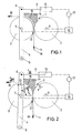
- the tensioning device shown in the two figures is arranged in the base of a strapping machine under its work table. At its heart, it has a pair of belt tensioning rollers 1, which is formed on the one hand by a stationary, rotatably mounted counter roller 2 and a swivel roller 3.
- the swivel roller 3 is rotatably mounted on a single-arm swivel lever 4, the swivel axis 5 of which runs parallel to the two axes of rotation 6, 7 of the counter and swivel roller 2, 3.
- the piston rod 9 engages a pneumatic cylinder 10, which acts on the swivel lever 4 in a direction at right angles to itself with a defined force F Cyl and thus presses the swivel roller 3 against the counter roller 2 of the tensioning roller pair 1.
- a band guide rail 14 is indicated by hatching with its band guide surface 15 describing a quarter inner circle sweeps the wrap angle 13.
- the tape guide rail 14 is used to guide the strapping 11 while the Strapping band 11 in the strapping machine.
- the two rollers 2, 3 are driven synchronously and in the opposite direction 20, 21 by a motor 16 which can be switched on and off via a control 17.
- the pneumatic cylinder 10 is also adjustable in its application pressure, so that the cylinder force F Cyl can be varied quickly and over wide ranges. This also takes place via a corresponding control of the pneumatic cylinder 10 through the intermediary of the control 17.
- Fig. 1 the inactive position of the back tensioning device is shown in the shooting the strapping 11 into the strapping machine he follows.
- the pneumatic cylinder 10 is positioned so that the piston rod 9 extended to the maximum and the belt tensioning roller pair 1 is open. This means that despite a rotation of the rollers 2, 3 against the direction of insertion 18 no force can be exerted on the strapping 11 can. This is carried out along the band guide surface 15 of the rail 14 the machine guided and in a known manner in the strapping machine handled.
- the tensioning device comes into action.
- the pneumatic cylinder 10 is activated and subjected to a force defined by the control 17.
- the pivot lever 4 is deflected clockwise with respect to FIG. 2 and the pivot roller 3 is advanced against the counter roller 2 while closing the roller gap 12.
- the strapping band 11 is gripped by the pair of tensioning rollers 1 and pulled in the tensioning direction 19.
- a force F R acts on the band, which is dependent on the contact pressure in the roller gap 12, the friction force that can be exerted on the band by the rollers 2, 3 and the wrap angle 13.
- the restoring force F builds up accordingly, the above process is repeated cyclically, the cycle time being in the order of a few thousandths to hundredsths of a second. It should also be pointed out that the swivel path of the swivel lever 4 moves in the plastic region of the band and is practically not measurable.
- the resetting force F back can be varied by setting the loading force F cyl via the pneumatic cylinder 10. It should also be noted that the torque of the motors does not have to be adjustable for the adjustment of the back tension F br . Rather, the invention provides a very simple mechanical control circuit in which the back tensioning process can be ended by a purely time control. If, for example, the actual tensioning process takes 0.08 seconds and the subsequent welding of the strapping band 0.05 seconds, it is sufficient to activate the band tensioning roller pair 1 over a period of, for example, 0.15 seconds with a defined application force F cyl on the pneumatic cylinder 10 to ensure a certain back tension and a welding of the tape while maintaining this back tension. The next strapping process can then be carried out by activating the tensioning roller pair 1 in the manner described.
- the application device for the Swivel lever 4 also by an electromagnetic lifting device or realized a spring arrangement mechanically adjustable in its pretension can be.
Landscapes
- Engineering & Computer Science (AREA)
- Mechanical Engineering (AREA)
- Basic Packing Technique (AREA)
Abstract
Description
- Fig. 1
- eine höchst schematische Seitenansicht einer Rückspannvorrichtung in inaktivem Zustand, und
- Fig. 2
- eine Seitenansicht analog Fig. 1 in aktivem Zustand der Rückspannvorrichtung.
- Für die Steuerung müssen nur ein Zeit-Sollwert und ein Sollwert für die
Beaufschlagungskraft des Pneumatikzylinders 10 vorgegeben werden.
Die eigentliche Regelung der Rückspannung erfolgt dann in situ" durch den mechanischen Regelkreis.

- Die Rückspannkraft ist linear von kleinsten Werten nahe 0 bis zu einem maximalen Kraftwert stufenlos einstellbar.
- Die Mechanik ist einfach auszuführen und leicht zu warten. Es sich keine aufwendigen Einstellarbeiten notwendig.
- Die Rückspannvorrichtung arbeitet sehr leise, da kein Bauteil große Hubstrecken überwinden muß.
Claims (9)
- Rückspannvorrichtung für Umreifungsmaschinen miteinem Bandspann-Rollenpaar (1), umfassend eine stationäre, drehbar gelagerte Konterrolle (2) und eine an einem Schwenkhebel (4) drehbar gelagerte, gegen die Konterrolle (2) zustellbare Schwenkrolle (3), zum Straffziehen des um einen Produktstapel gelegten Umreifungsbandes (11) in der Umreifungsmaschine, wobei das Umreifungsband (11) zwischen dem von Konter- (2) und Schwenkrolle (3) gebildeten Rollenspalt (12) hindurchgeführt und über einen Umschlingungswinkel (13) um die Schwenkrolle (3) herumgeführt ist,
gekennzeichnet durcheine mit dem Schwenkhebel (4) gekoppelte Beaufschlagungseinrichtung (10) zur definierten Beaufschlagung des Hebels (4) derart, daß die Schwenkrolle (3) mit einer definierten Beaufschlagungskraft (FZyl) gegen die Konterrolle (2) zustellbar ist, wobei die sich im Umreifungsband (11) beim Rückspannen aufbauende Rückspannkraft (FRück) der Beaufschlagungskraft (FZyl) so entgegengerichtet ist, daß bei Überschreiten der Beaufschlagungskraft (FZyl) die Schwenkrolle (3) kurzzeitig von der Konterrolle (2) abhebt und den Rückspannvorgang dadurch zyklisch unterbricht. - Rückspannvorrichtung nach Anspruch 1, gekennzeichnet durch eine Steuereinrichtung (17) zur zeitlichen Steuerung des Rollenantriebes beim Rückspannvorgang.
- Rückspannvorrichtung nach Anspruch 1 oder 2, dadurch gekennzeichnet, daß die definierte Beaufschlagung des Schwenkhebels (3) mit einer variablen Beaufschlagungskraft (FZyl) erfolgt.
- Rückspannvorrichtung nach einem der Ansprüche 1 bis 3, dadurch gekennzeichnet, daß die Beaufschlagungseinrichtung durch einen druckeinstellbaren Pneumatikzylinder (10) gebildet ist.
- Rückspannvorrichtung nach einem der Ansprüche 1 bis 3, dadurch gekennzeichnet, daß die Beaufschlagungseinrichtung durch einen elektromagnetische Hubvorrichtung gebildet ist.
- Rückspannvorrichtung nach einem der Ansprüche 1 bis 3, gekennzeichnet dadurch, daß die Beaufschlagungseinrichtung durch eine in ihrer Vorspannung mechanisch einstellbare Federanordnung gebildet ist.
- Rückspannvorrichtung nach einem der Ansprüche 1 bis 6, dadurch gekennzeichnet, daß der Umschlingungswinkel (13) etwa 90° beträgt.
- Rückspannvorrichtung nach einem der Ansprüche 1 bis 7, dadurch gekennzeichnet, daß das Umreifungsband (11) so von der Schwenkrolle (3) weggeführt ist, daß die Rückspannkraft (FRück) rechtwinklig zum Schwenkhebel (4) der Schwenkrolle (3) gerichtet ist.
- Rückspannvorrichtung nach einem der Ansprüche 1 bis , gekennzeichnet durch eine der Schwenkrolle (3) zugeordnete, den Umschlingungswinkel (13) des Umreifungsbandes (11) überstreichende Bandführungsschiene (14) zur Bandführung während des dem Rückspannen entgegengesetzten Einschießens des Umreifungsbandes (11) in die Umreifungsmaschine.
Applications Claiming Priority (2)
| Application Number | Priority Date | Filing Date | Title |
|---|---|---|---|
| DE19924352A DE19924352A1 (de) | 1999-05-27 | 1999-05-27 | Rückspannvorrichtung für Umreifungsmaschinen |
| DE19924352 | 1999-05-27 |
Publications (3)
| Publication Number | Publication Date |
|---|---|
| EP1055602A2 true EP1055602A2 (de) | 2000-11-29 |
| EP1055602A3 EP1055602A3 (de) | 2005-06-29 |
| EP1055602B1 EP1055602B1 (de) | 2006-06-07 |
Family
ID=7909388
Family Applications (1)
| Application Number | Title | Priority Date | Filing Date |
|---|---|---|---|
| EP00107627A Expired - Lifetime EP1055602B1 (de) | 1999-05-27 | 2000-04-08 | Rückspannvorrichtung für Umreifungsmaschinen |
Country Status (3)
| Country | Link |
|---|---|
| EP (1) | EP1055602B1 (de) |
| AT (1) | ATE328796T1 (de) |
| DE (2) | DE19924352A1 (de) |
Cited By (1)
| Publication number | Priority date | Publication date | Assignee | Title |
|---|---|---|---|---|
| US7082872B2 (en) | 2003-01-21 | 2006-08-01 | Eam-Mosca Corporation | Strap tensioning apparatus |
Family Cites Families (5)
| Publication number | Priority date | Publication date | Assignee | Title |
|---|---|---|---|---|
| DE3249558A1 (de) * | 1982-05-29 | 1985-08-14 | Hoesch Ag, 4600 Dortmund | Vorschub- und spannvorrichtung fuer ein um ein packstueck zu spannendes umreifungsband |
| DE3249559A1 (de) * | 1982-05-29 | 1985-08-14 | Hoesch Ag, 4600 Dortmund | Vorschub- und spannvorrichtung fuer ein um ein packstueck zu spannendes umreifungsband |
| JP2857280B2 (ja) * | 1992-06-10 | 1999-02-17 | ストラパック株式会社 | 梱包機におけるバンド供給・引締方法及び装置 |
| DE19505093C1 (de) * | 1995-02-15 | 1996-10-17 | Karlheinz Traeger | Bandspannvorrichtung |
| IT1284429B1 (it) * | 1996-03-14 | 1998-05-21 | Sestese Off Mec | Dispositivo di controllo del trascinamento della reggia in una testa reggiatrice |
-
1999
- 1999-05-27 DE DE19924352A patent/DE19924352A1/de not_active Withdrawn
-
2000
- 2000-04-08 EP EP00107627A patent/EP1055602B1/de not_active Expired - Lifetime
- 2000-04-08 DE DE50012885T patent/DE50012885D1/de not_active Expired - Fee Related
- 2000-04-08 AT AT00107627T patent/ATE328796T1/de not_active IP Right Cessation
Cited By (1)
| Publication number | Priority date | Publication date | Assignee | Title |
|---|---|---|---|---|
| US7082872B2 (en) | 2003-01-21 | 2006-08-01 | Eam-Mosca Corporation | Strap tensioning apparatus |
Also Published As
| Publication number | Publication date |
|---|---|
| DE50012885D1 (de) | 2006-07-20 |
| EP1055602A3 (de) | 2005-06-29 |
| ATE328796T1 (de) | 2006-06-15 |
| EP1055602B1 (de) | 2006-06-07 |
| DE19924352A1 (de) | 2000-11-30 |
Similar Documents
| Publication | Publication Date | Title |
|---|---|---|
| DE2324293C3 (de) | Vorrichtung zum Umschnüren eines Ballens o.dgl | |
| EP2815857B1 (de) | Schere | |
| EP0968919B1 (de) | Vorrichtung zum Umwickeln von quaderförmigen Gegenständen mit einem Bahnförmigen Umwickelmaterial | |
| CH640188A5 (de) | Spannbandbindemaschine. | |
| DE19516825A1 (de) | Drahtliefervorrichtung | |
| DE1942410A1 (de) | Maschine zum Fertigen von Beuteln | |
| DE3042383A1 (de) | Glaettvorrichtung | |
| DE4013656C2 (de) | Vorrichtung zum Spleißen von Bahnen, insbesondere von Papierbahnen für die Herstellung von Wellpappe | |
| DE2623907A1 (de) | Straffzieheinrichtung fuer banderoliermaschinen | |
| DE3818526A1 (de) | Bandfestziehvorrichtung fuer eine verschnuermaschine | |
| EP0313781A2 (de) | Vorrichtung zum Herstellen von tragbaren, rohrförmigen Paketen aus Druckprodukten | |
| EP0652176B1 (de) | Wickelvorrichtung für flexible Flächengebilde sowie Verfahren zum Aufwickeln von flexiblen Flächengebilden | |
| DE2507467A1 (de) | Vorrichtung zum verbinden von naegeln oder dergleichen zu nagelstreifen | |
| EP1055602B1 (de) | Rückspannvorrichtung für Umreifungsmaschinen | |
| EP0232553A1 (de) | Einrichtung zum Aufwickeln eines kontinuierlich anfallenden Schuppenstromes von biegsamen Flächengebilden zu einem Wickel | |
| DE2837164A1 (de) | Umreifungsmaschine fuer das umreifen von packguetern | |
| EP0847922B1 (de) | Vorrichtung zum Umreifen von Packstücken | |
| EP0817688A1 (de) | Bandhaspel | |
| EP1280725B1 (de) | Vorrichtung und verfahren zum spannen einer zu fördernden, flächigen materialbahn mittels drehzahlunterschied | |
| DE69200013T2 (de) | Gerät zum Spannen von Bändern, insbesondere Bändern befertigt auf Möbelrahmen. | |
| DE69815999T2 (de) | Aufwickelvorrichtung für Furnier | |
| DE58642C (de) | Rotationsdruckpresse zum Bedrucken von Bogen verschiedener Gröfse | |
| DE2534157A1 (de) | Straffzieheinrichtung fuer banderoliermaschinen | |
| DE3044458C2 (de) | ||
| EP0563649A2 (de) | Verfahren und Vorrichtung zur Bildung einer geschlossenen Umhüllung um einen Gegenstand |
Legal Events
| Date | Code | Title | Description |
|---|---|---|---|
| PUAI | Public reference made under article 153(3) epc to a published international application that has entered the european phase |
Free format text: ORIGINAL CODE: 0009012 |
|
| AK | Designated contracting states |
Kind code of ref document: A2 Designated state(s): AT BE CH CY DE DK ES FI FR GB GR IE IT LI LU MC NL PT SE |
|
| AX | Request for extension of the european patent |
Free format text: AL;LT;LV;MK;RO;SI |
|
| PUAL | Search report despatched |
Free format text: ORIGINAL CODE: 0009013 |
|
| AK | Designated contracting states |
Kind code of ref document: A3 Designated state(s): AT BE CH CY DE DK ES FI FR GB GR IE IT LI LU MC NL PT SE |
|
| AX | Request for extension of the european patent |
Extension state: AL LT LV MK RO SI |
|
| 17P | Request for examination filed |
Effective date: 20050823 |
|
| GRAP | Despatch of communication of intention to grant a patent |
Free format text: ORIGINAL CODE: EPIDOSNIGR1 |
|
| GRAS | Grant fee paid |
Free format text: ORIGINAL CODE: EPIDOSNIGR3 |
|
| AKX | Designation fees paid |
Designated state(s): AT BE CH CY DE DK ES FI FR GB GR IE IT LI LU MC NL PT SE |
|
| GRAA | (expected) grant |
Free format text: ORIGINAL CODE: 0009210 |
|
| AK | Designated contracting states |
Kind code of ref document: B1 Designated state(s): AT BE CH CY DE DK ES FI FR GB GR IE IT LI LU MC NL PT SE |
|
| PG25 | Lapsed in a contracting state [announced via postgrant information from national office to epo] |
Ref country code: IT Free format text: LAPSE BECAUSE OF FAILURE TO SUBMIT A TRANSLATION OF THE DESCRIPTION OR TO PAY THE FEE WITHIN THE PRE;WARNING: LAPSES OF ITALIAN PATENTS WITH EFFECTIVE DATE BEFORE 2007 MAY HAVE OCCURRED AT ANY TIME BEFORE 2007. THE CORRECT EFFECTIVE DATE MAY BE DIFFERENT FROM THE ONE RECORDED.SCRIBED TIME-LIMIT Effective date: 20060607 Ref country code: NL Free format text: LAPSE BECAUSE OF FAILURE TO SUBMIT A TRANSLATION OF THE DESCRIPTION OR TO PAY THE FEE WITHIN THE PRESCRIBED TIME-LIMIT Effective date: 20060607 Ref country code: FI Free format text: LAPSE BECAUSE OF FAILURE TO SUBMIT A TRANSLATION OF THE DESCRIPTION OR TO PAY THE FEE WITHIN THE PRESCRIBED TIME-LIMIT Effective date: 20060607 Ref country code: IE Free format text: LAPSE BECAUSE OF FAILURE TO SUBMIT A TRANSLATION OF THE DESCRIPTION OR TO PAY THE FEE WITHIN THE PRESCRIBED TIME-LIMIT Effective date: 20060607 |
|
| REG | Reference to a national code |
Ref country code: GB Ref legal event code: FG4D Free format text: NOT ENGLISH |
|
| REG | Reference to a national code |
Ref country code: CH Ref legal event code: EP |
|
| GBT | Gb: translation of ep patent filed (gb section 77(6)(a)/1977) |
Effective date: 20060607 |
|
| REG | Reference to a national code |
Ref country code: IE Ref legal event code: FG4D Free format text: LANGUAGE OF EP DOCUMENT: GERMAN |
|
| REF | Corresponds to: |
Ref document number: 50012885 Country of ref document: DE Date of ref document: 20060720 Kind code of ref document: P |
|
| PG25 | Lapsed in a contracting state [announced via postgrant information from national office to epo] |
Ref country code: DK Free format text: LAPSE BECAUSE OF FAILURE TO SUBMIT A TRANSLATION OF THE DESCRIPTION OR TO PAY THE FEE WITHIN THE PRESCRIBED TIME-LIMIT Effective date: 20060907 Ref country code: SE Free format text: LAPSE BECAUSE OF FAILURE TO SUBMIT A TRANSLATION OF THE DESCRIPTION OR TO PAY THE FEE WITHIN THE PRESCRIBED TIME-LIMIT Effective date: 20060907 |
|
| PG25 | Lapsed in a contracting state [announced via postgrant information from national office to epo] |
Ref country code: ES Free format text: LAPSE BECAUSE OF FAILURE TO SUBMIT A TRANSLATION OF THE DESCRIPTION OR TO PAY THE FEE WITHIN THE PRESCRIBED TIME-LIMIT Effective date: 20060918 |
|
| PG25 | Lapsed in a contracting state [announced via postgrant information from national office to epo] |
Ref country code: PT Free format text: LAPSE BECAUSE OF FAILURE TO SUBMIT A TRANSLATION OF THE DESCRIPTION OR TO PAY THE FEE WITHIN THE PRESCRIBED TIME-LIMIT Effective date: 20061107 |
|
| NLV1 | Nl: lapsed or annulled due to failure to fulfill the requirements of art. 29p and 29m of the patents act | ||
| ET | Fr: translation filed | ||
| REG | Reference to a national code |
Ref country code: IE Ref legal event code: FD4D |
|
| PLBI | Opposition filed |
Free format text: ORIGINAL CODE: 0009260 |
|
| 26 | Opposition filed |
Opponent name: CYKLOP GMBH Effective date: 20070305 |
|
| PLAX | Notice of opposition and request to file observation + time limit sent |
Free format text: ORIGINAL CODE: EPIDOSNOBS2 |
|
| PLAF | Information modified related to communication of a notice of opposition and request to file observations + time limit |
Free format text: ORIGINAL CODE: EPIDOSCOBS2 |
|
| PLAF | Information modified related to communication of a notice of opposition and request to file observations + time limit |
Free format text: ORIGINAL CODE: EPIDOSCOBS2 |
|
| PLBP | Opposition withdrawn |
Free format text: ORIGINAL CODE: 0009264 |
|
| PLBB | Reply of patent proprietor to notice(s) of opposition received |
Free format text: ORIGINAL CODE: EPIDOSNOBS3 |
|
| REG | Reference to a national code |
Ref country code: CH Ref legal event code: PL |
|
| BERE | Be: lapsed |
Owner name: SMB SCHWEDE MASCHINENBAU G.M.B.H. Effective date: 20070430 |
|
| PLBD | Termination of opposition procedure: decision despatched |
Free format text: ORIGINAL CODE: EPIDOSNOPC1 |
|
| PG25 | Lapsed in a contracting state [announced via postgrant information from national office to epo] |
Ref country code: LI Free format text: LAPSE BECAUSE OF NON-PAYMENT OF DUE FEES Effective date: 20070430 Ref country code: CH Free format text: LAPSE BECAUSE OF NON-PAYMENT OF DUE FEES Effective date: 20070430 |
|
| PG25 | Lapsed in a contracting state [announced via postgrant information from national office to epo] |
Ref country code: BE Free format text: LAPSE BECAUSE OF NON-PAYMENT OF DUE FEES Effective date: 20070430 |
|
| PLBM | Termination of opposition procedure: date of legal effect published |
Free format text: ORIGINAL CODE: 0009276 |
|
| STAA | Information on the status of an ep patent application or granted ep patent |
Free format text: STATUS: OPPOSITION PROCEDURE CLOSED |
|
| 27C | Opposition proceedings terminated |
Effective date: 20080208 |
|
| PG25 | Lapsed in a contracting state [announced via postgrant information from national office to epo] |
Ref country code: AT Free format text: LAPSE BECAUSE OF NON-PAYMENT OF DUE FEES Effective date: 20070408 |
|
| PGFP | Annual fee paid to national office [announced via postgrant information from national office to epo] |
Ref country code: IT Payment date: 20080426 Year of fee payment: 9 |
|
| PGFP | Annual fee paid to national office [announced via postgrant information from national office to epo] |
Ref country code: DE Payment date: 20080623 Year of fee payment: 9 |
|
| PGFP | Annual fee paid to national office [announced via postgrant information from national office to epo] |
Ref country code: FR Payment date: 20080418 Year of fee payment: 9 |
|
| PGFP | Annual fee paid to national office [announced via postgrant information from national office to epo] |
Ref country code: GB Payment date: 20080423 Year of fee payment: 9 |
|
| PG25 | Lapsed in a contracting state [announced via postgrant information from national office to epo] |
Ref country code: MC Free format text: LAPSE BECAUSE OF NON-PAYMENT OF DUE FEES Effective date: 20070430 |
|
| PG25 | Lapsed in a contracting state [announced via postgrant information from national office to epo] |
Ref country code: LU Free format text: LAPSE BECAUSE OF NON-PAYMENT OF DUE FEES Effective date: 20070408 Ref country code: CY Free format text: LAPSE BECAUSE OF FAILURE TO SUBMIT A TRANSLATION OF THE DESCRIPTION OR TO PAY THE FEE WITHIN THE PRESCRIBED TIME-LIMIT Effective date: 20060607 |
|
| GBPC | Gb: european patent ceased through non-payment of renewal fee |
Effective date: 20090408 |
|
| REG | Reference to a national code |
Ref country code: FR Ref legal event code: ST Effective date: 20091231 |
|
| PG25 | Lapsed in a contracting state [announced via postgrant information from national office to epo] |
Ref country code: DE Free format text: LAPSE BECAUSE OF NON-PAYMENT OF DUE FEES Effective date: 20091103 |
|
| PG25 | Lapsed in a contracting state [announced via postgrant information from national office to epo] |
Ref country code: FR Free format text: LAPSE BECAUSE OF NON-PAYMENT OF DUE FEES Effective date: 20091222 Ref country code: GB Free format text: LAPSE BECAUSE OF NON-PAYMENT OF DUE FEES Effective date: 20090408 |
|
| PG25 | Lapsed in a contracting state [announced via postgrant information from national office to epo] |
Ref country code: IT Free format text: LAPSE BECAUSE OF NON-PAYMENT OF DUE FEES Effective date: 20090408 |
|
| PG25 | Lapsed in a contracting state [announced via postgrant information from national office to epo] |
Ref country code: GR Free format text: LAPSE BECAUSE OF NON-PAYMENT OF DUE FEES Effective date: 20070430 |