EP1055635A2 - Grue avec une flèche télescopique - Google Patents
Grue avec une flèche télescopique Download PDFInfo
- Publication number
- EP1055635A2 EP1055635A2 EP00250048A EP00250048A EP1055635A2 EP 1055635 A2 EP1055635 A2 EP 1055635A2 EP 00250048 A EP00250048 A EP 00250048A EP 00250048 A EP00250048 A EP 00250048A EP 1055635 A2 EP1055635 A2 EP 1055635A2
- Authority
- EP
- European Patent Office
- Prior art keywords
- coupling
- locking
- telescopic
- crane according
- locking bolt
- Prior art date
- Legal status (The legal status is an assumption and is not a legal conclusion. Google has not performed a legal analysis and makes no representation as to the accuracy of the status listed.)
- Granted
Links
Images





Classifications
-
- B—PERFORMING OPERATIONS; TRANSPORTING
- B66—HOISTING; LIFTING; HAULING
- B66C—CRANES; LOAD-ENGAGING ELEMENTS OR DEVICES FOR CRANES, CAPSTANS, WINCHES, OR TACKLES
- B66C23/00—Cranes comprising essentially a beam, boom, or triangular structure acting as a cantilever and mounted for translatory of swinging movements in vertical or horizontal planes or a combination of such movements, e.g. jib-cranes, derricks, tower cranes
- B66C23/62—Constructional features or details
- B66C23/64—Jibs
- B66C23/70—Jibs constructed of sections adapted to be assembled to form jibs or various lengths
- B66C23/701—Jibs constructed of sections adapted to be assembled to form jibs or various lengths telescopic
- B66C23/708—Jibs constructed of sections adapted to be assembled to form jibs or various lengths telescopic locking devices for telescopic jibs
Definitions
- the invention relates to a crane with a telescopic boom according to the preamble of claim 1.
- a crane with a telescopic boom is known from DE 198 24 672 A1.
- This consists of a basic box and individual ones arranged in it telescopic shots, which after releasing locking Pin connections through coupling with only one single-stage hydraulic piston-cylinder unit Extendable and retractable and in the extended or retracted position are lockable, the cylinder housing of the piston-cylinder unit with its rear end is attached to the inner end of the boom and the Piston rod at the front end with a parallel to the piston-cylinder unit lying guide and pulling device is connected, at the inner end of one Coupling and locking unit is attached, which with recordings of the telescopic shots can be coupled and locked.
- the clutch and Locking unit has two mechanically via a grooves Sliding actuated coupling pin on in a horizontal plane lying right and left in at the inner end of each shot Recordings can be pushed in and out.
- the sliding piece is actuated via an axially arranged connected to the coupling and locking unit Piston-cylinder unit, the means for retracting the spring-loaded Locking bolt can only be operated when the clutch and Locking unit with the receptacles of the extractor or extractor Shot is coupled and loosening the coupling bolt with the respective shot can only be done if the respective spring-loaded locking bolt is set.
- the driver device consists of a hydraulic block with each other opposite cylinders for the one and formed by their pistons extendable bolt locking the respective shot and one perpendicular to it arranged hydraulic piston-cylinder unit for actuating the respective Locking bolt.
- the hydraulic elements of the driver device are in place so that the radial piston-cylinder unit is retractable of the respective locking bolt can only be operated if the Driver device with the out or bag-telescopic shot over the locking bolt is coupled.
- a telescopic boom known from DE 196 41 191 A1
- the shots to be telescoped by means of two Endless ropes with one exit and one entry side in connection with a rope drive and deflection rollers extendable and retractable. They are in the retracted and extended positions Shots against by means of a locking device assigned to each shot relative axial movement noticeable.
- the cable drive and two pulleys are on Base of the base box and a third pulley is on the rope drive opposite end of a cantilevered within the shots and on Basic box rigidly attached guide tube arranged.
- the benchmarks of Rope ends are on a holding device with a gripping device is slidably disposed on the guide tube.
- the object of the invention is to provide a crane with a telescopic boom further develop that by simplifying the clutch and Locking unit space and weight can be saved.
- the coupling part with an axis movable locking bolt of a locking element in a form-fitting manner can be coupled.
- the special thing about this arrangement is that in the unlocked position the locking bolt in combination with the coupling part the coupling between Sliding device and the respective shot to be telescoped in and out represents.
- the two functions were coupling and locking divided into two separately operated elements, with the Both functions had to be linked to ensure that the each shot is bolted safely in every operating phase, be it over the Coupling bolt, be it over the locking bolt or bolts.
- the advantage of the proposed arrangement is that fewer parts needed to save weight without the required Safety concept of interfering with the safe bolting of the shots. Also at The new arrangement ensures that the respective shot is either locked or coupled. Another advantage is the space saving, as with the previously usual separately arranged elements more space was needed, which was the smallest can cause problems for telescopic shot.
- the displacement device for moving the shots can be a cable drive, a single or multi-stage piston-cylinder unit or several piston-cylinder units to be operated in parallel his.
- a locking element in the respective shot to be telescoped is arranged in the middle above or in the middle below.
- the corresponding recording of the to telescopic shot comprehensive shot is in the top wall or in the bottom wall.
- the Shifting device attacking moment an arrangement with two each other provide opposite locking elements.
- the axis of these two Locking elements or their cooperating coupling elements cut the Center axis of the displacement device at a right angle.
- the two locking elements in the two opposite one another Side wall areas arranged. An arrangement is also conceivable in which the two locking elements are arranged in the top and bottom wall.
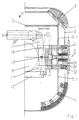
- FIG. 1 shows in cross section and Figure 2 in a view the right half of a Telescopic boom in the area of the rear storage. Only two are shown here Telescopic shots 1, 2 to illustrate the principle.
- the novel is applicable Coupling and locking system also for telescopic booms with more than two telescopic telescopic shots.
- sliding elements 3, 4 preferably made of polyamide.
- sliding elements 3, 4 preferably made of polyamide.
- a locking bolt 24 of the Locking element 6 is displaceable in the axial direction Coupling part 15 of a coupling element 7 can be coupled.
- the coupling element 7 is on one displaceable element 8 of a displacement device, not shown attached.
- the clutch part 15 is actuated by means of a crosswise to Longitudinal axis arranged hydraulic piston-cylinder unit 9. Die Longitudinal movement of the displaceable element 8 of the displacement device is in Figure 2 identified by a double arrow 10. It means upwards going arrow the direction for telescoping and the going down arrow the direction for telescoping.
- the mechanical connection of the hydraulic Piston-cylinder unit 9 with the coupling part 15 takes place via a lever 11, which with its upper end on the hydraulic piston-cylinder unit 9 and with its lower end is hinged to a fixed linkage 12 and with a bolt 13 with the coupling part 15 is connected.
- the state shown in Figures 1 and 2 shows the Locking position between the telescopic section 2 with the comprehensive Telescopic shot 1 and the possibility by means of the displaceable element 8 Sliding device the associated coupling element 7 according to the Bring double arrow 10 into position.
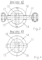
- Figures 3 - 6 show views of both the coupling element 7 and the Locking element 6.
- the coupling element 7 has a sleeve 14, which is firmly connected to the displaceable element 8 of the displacement device.
- a coupling part 15 is arranged, which by means of the bolt 13 and Lever 11 is axially movable.
- For the movement of the lever 11 are in the sleeve 14th axially extending recesses 16, 17 milled (see Fig. 1).
- View X 3 shows that the coupling part 15 has a crescent-shaped recess 18. Furthermore, the coupling part 15 has a transverse recess 19, which makes it possible to connect the coupling part 15 to the locking bolt 24 in a form-fitting manner. The way in which this is done is explained in more detail in FIGS. 7-9.
- the locking element 6 is in accordance with the representations in FIG. 2 and FIG. 5 and 6 constructed from the following elements.
- a sleeve 20 is attached to the has the same outer and inner diameter as the sleeve 14 for the Coupling element 7.
- a sliding bushing 21 is inserted into the sleeve 20 Facilitation of the axial sliding of the locking bolt 24.
- the bottom area of the Slide bushing 21 has a transverse web 29 which is arranged, for example, by welding the sleeve 20 is attached.
- This crossbar 29 forms two with each other with the sleeve 20 Opposite sickle-shaped openings through which the also sickle-shaped trained webs 22, 23 of the locking bolt 24 are movable (Fig.5).
- a central recess 30 of the locking bolt 24 is a spring 25 arranged, on the one hand on the end face of the recess of the Locking bolt 24 and on the other hand supported on the crossbar 29.
- By the Locking bolt 24 and through the crossbar 29 extends in the axial central position a screw 26, on which in the end region of the thread a mushroom-shaped Coupling piece 27 is screwed on.
- the sliding bush is secured axially by a Ring with several fastening screws 28 arranged on the circumference (Fig. 2).
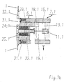
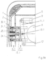
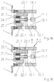
- FIGS. 7a, b to 9a-c show the essential phases for unlocking with the proposed device shown.
- Figures 7a, 8a and 9a Telescopic shot shown This includes the two marked 1 and 2 Telescopic shots.
- the left partial half is in FIG. 7a Telescopic boom reproduced.
- Figure 7b shows the longitudinal section of Figure 7a.
- FIGS. 7a, 7b show a state in which the Telescopic shot 2 is locked with the telescopic shot 1 surrounding it.
- FIGS. 8a-8c show a further phase of the unlocking process.
- the coupling element 7.1 has been displaced so far, until the coupling part 15.1 by means of the piston-cylinder unit 9 and the lever 11.1 can be moved to the left.
- This shift is necessary for the Transverse recess 19.1 in the coupling part 15.1 at the level of the coupling piece 27.1 of the locking element 6.1.
- the coupling piece 27.1 comes in positively Engagement with the recess 19.1 (drawing 8c).
- FIGS. 9a-9c The last phase of the unlocking process is shown in FIGS. 9a-9c.
- the coupling piece 27.1 of the locking bolt 24.1 in the Recess 19.1 of the coupling part 15.1 becomes the hydraulic piston-cylinder unit 9 activated and against the force of the spring 25.1 the coupling part 15.1 moved to the right by means of the lever 11.1.
- the locking bolt 24.1 moves out of the recess 31.1 of the enclosing telescopic section 1 and thus the two telescopic sections 1, 2 unlocked, wherein in the right half of the not shown here Locking bolt 24 in the same way by means of the coupling part 15 has been pulled.
Landscapes
- Engineering & Computer Science (AREA)
- Mechanical Engineering (AREA)
- Jib Cranes (AREA)
Applications Claiming Priority (4)
| Application Number | Priority Date | Filing Date | Title |
|---|---|---|---|
| DE19920634 | 1999-04-29 | ||
| DE19920634 | 1999-04-29 | ||
| DE10007773A DE10007773B4 (de) | 1999-04-29 | 2000-02-14 | Kran mit einem Teleskopausleger |
| DE10007773 | 2000-02-14 |
Publications (3)
| Publication Number | Publication Date |
|---|---|
| EP1055635A2 true EP1055635A2 (fr) | 2000-11-29 |
| EP1055635A3 EP1055635A3 (fr) | 2003-09-17 |
| EP1055635B1 EP1055635B1 (fr) | 2005-01-12 |
Family
ID=26004434
Family Applications (1)
| Application Number | Title | Priority Date | Filing Date |
|---|---|---|---|
| EP00250048A Expired - Lifetime EP1055635B1 (fr) | 1999-04-29 | 2000-02-16 | Grue avec une flèche télescopique |
Country Status (2)
| Country | Link |
|---|---|
| EP (1) | EP1055635B1 (fr) |
| AT (1) | ATE286849T1 (fr) |
Cited By (5)
| Publication number | Priority date | Publication date | Assignee | Title |
|---|---|---|---|---|
| DE202006019308U1 (de) * | 2006-12-21 | 2008-04-30 | Liebherr-Werk Ehingen Gmbh | Teleskopschuß |
| DE202007002203U1 (de) * | 2007-02-14 | 2008-06-26 | Liebherr-Werk Ehingen Gmbh | Teleskopschuß |
| CN105712219A (zh) * | 2016-05-06 | 2016-06-29 | 北汽福田汽车股份有限公司 | 一种起重机及其伸缩臂架 |
| WO2019178067A1 (fr) * | 2018-03-12 | 2019-09-19 | Manitowoc Crane Companies, Llc | Flèche de grue télescopique à broches |
| CN113415742A (zh) * | 2021-08-02 | 2021-09-21 | 王凯 | 起重机伸缩臂滑块组件 |
Family Cites Families (5)
| Publication number | Priority date | Publication date | Assignee | Title |
|---|---|---|---|---|
| DE3510710A1 (de) * | 1985-03-23 | 1986-10-02 | Fried. Krupp Gmbh, 4300 Essen | Teleskopkran |
| DE3908571A1 (de) * | 1989-03-16 | 1990-09-20 | Century Ii Gmbh Mobilkrane | Vorrichtung zum wenigstens zeitweisen koppeln der beiden letzten ineinander gefuehrten teleskopischen auslegerschuesse eines kranauslegers |
| DE4344795A1 (de) * | 1993-12-28 | 1995-06-29 | Liebherr Werk Ehingen | Fahrbarer Kran mit einem Teleskopausleger |
| DE19641191A1 (de) * | 1996-09-24 | 1998-03-26 | Mannesmann Ag | Teleskopausleger, insbesondere für stationäre und fahrbare Krane |
| DE19824672A1 (de) * | 1997-05-28 | 1998-12-03 | Mannesmann Ag | Kran mit einem Teleskopausleger |
-
2000
- 2000-02-16 AT AT00250048T patent/ATE286849T1/de not_active IP Right Cessation
- 2000-02-16 EP EP00250048A patent/EP1055635B1/fr not_active Expired - Lifetime
Cited By (9)
| Publication number | Priority date | Publication date | Assignee | Title |
|---|---|---|---|---|
| DE202006019308U1 (de) * | 2006-12-21 | 2008-04-30 | Liebherr-Werk Ehingen Gmbh | Teleskopschuß |
| DE202007002203U1 (de) * | 2007-02-14 | 2008-06-26 | Liebherr-Werk Ehingen Gmbh | Teleskopschuß |
| EP1958917A1 (fr) | 2007-02-14 | 2008-08-20 | Liebherr-Werk Ehingen GmbH | Coup de télescopage |
| CN105712219A (zh) * | 2016-05-06 | 2016-06-29 | 北汽福田汽车股份有限公司 | 一种起重机及其伸缩臂架 |
| WO2019178067A1 (fr) * | 2018-03-12 | 2019-09-19 | Manitowoc Crane Companies, Llc | Flèche de grue télescopique à broches |
| CN111836776A (zh) * | 2018-03-12 | 2020-10-27 | 马尼托瓦克起重机有限责任公司 | 销接式伸缩起重机吊臂 |
| US11401135B2 (en) | 2018-03-12 | 2022-08-02 | Manitowoc Crane Companies, Llc | Pinned telescoping crane boom |
| CN111836776B (zh) * | 2018-03-12 | 2023-08-08 | 马尼托瓦克起重机有限责任公司 | 销接式伸缩起重机吊臂 |
| CN113415742A (zh) * | 2021-08-02 | 2021-09-21 | 王凯 | 起重机伸缩臂滑块组件 |
Also Published As
| Publication number | Publication date |
|---|---|
| EP1055635A3 (fr) | 2003-09-17 |
| EP1055635B1 (fr) | 2005-01-12 |
| ATE286849T1 (de) | 2005-01-15 |
Similar Documents
| Publication | Publication Date | Title |
|---|---|---|
| EP0984895B1 (fr) | Grue a fleche telescopique | |
| DE19811813B4 (de) | Seitliche Auslegerverriegelung | |
| DE19824671C2 (de) | Kran mit einem Teleskopausleger | |
| EP0661234B1 (fr) | Grue mobile avec un flèche télescopique | |
| EP1072554B1 (fr) | Grue à flèche téléscopique | |
| DE19744328C1 (de) | Seitenstrebe für den Unterlenker eines Traktors | |
| DE10048224B4 (de) | Verriegelungseinheit für einen Teleskopausleger eines Krans | |
| DE10007773B4 (de) | Kran mit einem Teleskopausleger | |
| DE19641193C2 (de) | Teleskopausleger, insbesondere für stationäre oder fahrbare Krane | |
| DE10004838B4 (de) | Kran mit einem Teleskopausleger | |
| EP1293471B1 (fr) | Flèche télescopique | |
| DE10062517A1 (de) | Teleskopausleger | |
| EP1055635B1 (fr) | Grue avec une flèche télescopique | |
| DE19631547B4 (de) | Teleskopausleger, insbesondere für stationäre oder fahrbare Krane | |
| DE19926131B4 (de) | Teleskop-Ausleger | |
| DE29824867U1 (de) | Kran mit einem Teleskopausleger | |
| DE20120964U1 (de) | Abstützvorrichtung für Baumaschinen wie Hydraulikbagger u.dgl. | |
| EP1321426B1 (fr) | Flèche télescopique | |
| DE19641191A1 (de) | Teleskopausleger, insbesondere für stationäre und fahrbare Krane | |
| EP1321427B1 (fr) | Flèche télescopique | |
| EP1034917A2 (fr) | Presse avec dispositif de verrouillage pour coulisseau de presse | |
| DE2106983A1 (de) | Teleskopierbarer Kranausleger | |
| EP4479337B1 (fr) | Dispositif de verrouillage pour cylindre télescopique | |
| DE20003355U1 (de) | Kran mit einem Teleskopausleger | |
| DE19616167A1 (de) | Teleskopausleger, insbesondere für stationäre oder fahrbare Krane |
Legal Events
| Date | Code | Title | Description |
|---|---|---|---|
| PUAI | Public reference made under article 153(3) epc to a published international application that has entered the european phase |
Free format text: ORIGINAL CODE: 0009012 |
|
| AK | Designated contracting states |
Kind code of ref document: A2 Designated state(s): AT BE CH CY DE DK ES FI FR GB GR IE IT LI LU MC NL PT SE |
|
| AX | Request for extension of the european patent |
Free format text: AL;LT;LV;MK;RO;SI |
|
| PUAL | Search report despatched |
Free format text: ORIGINAL CODE: 0009013 |
|
| AK | Designated contracting states |
Kind code of ref document: A3 Designated state(s): AT BE CH CY DE DK ES FI FR GB GR IE IT LI LU MC NL PT SE |
|
| AX | Request for extension of the european patent |
Extension state: AL LT LV MK RO SI |
|
| RAP1 | Party data changed (applicant data changed or rights of an application transferred) |
Owner name: TEREX-DEMAG GMBH & CO. KG |
|
| 17P | Request for examination filed |
Effective date: 20040115 |
|
| AKX | Designation fees paid |
Designated state(s): AT BE CH CY DE DK ES FI FR GB GR IE IT LI LU MC NL PT SE |
|
| GRAP | Despatch of communication of intention to grant a patent |
Free format text: ORIGINAL CODE: EPIDOSNIGR1 |
|
| GRAS | Grant fee paid |
Free format text: ORIGINAL CODE: EPIDOSNIGR3 |
|
| RBV | Designated contracting states (corrected) |
Designated state(s): AT CH DE LI |
|
| GRAA | (expected) grant |
Free format text: ORIGINAL CODE: 0009210 |
|
| AK | Designated contracting states |
Kind code of ref document: B1 Designated state(s): AT CH DE LI |
|
| REG | Reference to a national code |
Ref country code: CH Ref legal event code: NV Representative=s name: E. BLUM & CO. PATENTANWAELTE Ref country code: CH Ref legal event code: EP |
|
| PG25 | Lapsed in a contracting state [announced via postgrant information from national office to epo] |
Ref country code: AT Free format text: LAPSE BECAUSE OF NON-PAYMENT OF DUE FEES Effective date: 20050216 |
|
| REF | Corresponds to: |
Ref document number: 50009188 Country of ref document: DE Date of ref document: 20050217 Kind code of ref document: P |
|
| REG | Reference to a national code |
Ref country code: IE Ref legal event code: FG4D Free format text: GERMAN |
|
| PG25 | Lapsed in a contracting state [announced via postgrant information from national office to epo] |
Ref country code: LI Free format text: LAPSE BECAUSE OF NON-PAYMENT OF DUE FEES Effective date: 20050228 Ref country code: CH Free format text: LAPSE BECAUSE OF NON-PAYMENT OF DUE FEES Effective date: 20050228 |
|
| PG25 | Lapsed in a contracting state [announced via postgrant information from national office to epo] |
Ref country code: DE Free format text: LAPSE BECAUSE OF NON-PAYMENT OF DUE FEES Effective date: 20050901 |
|
| REG | Reference to a national code |
Ref country code: CH Ref legal event code: PL |
|
| PLBE | No opposition filed within time limit |
Free format text: ORIGINAL CODE: 0009261 |
|
| STAA | Information on the status of an ep patent application or granted ep patent |
Free format text: STATUS: NO OPPOSITION FILED WITHIN TIME LIMIT |
|
| 26N | No opposition filed |
Effective date: 20051013 |