EP1055773B1 - Band für eine Schuhpresse und Verfahren zu seiner Herstellung - Google Patents
Band für eine Schuhpresse und Verfahren zu seiner Herstellung Download PDFInfo
- Publication number
- EP1055773B1 EP1055773B1 EP00106055A EP00106055A EP1055773B1 EP 1055773 B1 EP1055773 B1 EP 1055773B1 EP 00106055 A EP00106055 A EP 00106055A EP 00106055 A EP00106055 A EP 00106055A EP 1055773 B1 EP1055773 B1 EP 1055773B1
- Authority
- EP
- European Patent Office
- Prior art keywords
- layer
- yarn
- base material
- belt
- shoe
- Prior art date
- Legal status (The legal status is an assumption and is not a legal conclusion. Google has not performed a legal analysis and makes no representation as to the accuracy of the status listed.)
- Expired - Lifetime
Links
- 238000004519 manufacturing process Methods 0.000 title claims description 14
- 238000000034 method Methods 0.000 title claims description 13
- 239000011347 resin Substances 0.000 claims description 84
- 229920005989 resin Polymers 0.000 claims description 84
- 239000000463 material Substances 0.000 claims description 79
- 238000004804 winding Methods 0.000 claims description 26
- 239000011295 pitch Substances 0.000 claims description 18
- 239000002131 composite material Substances 0.000 claims description 11
- 230000008859 change Effects 0.000 claims description 7
- 238000005452 bending Methods 0.000 description 26
- 239000004744 fabric Substances 0.000 description 22
- 229920000728 polyester Polymers 0.000 description 13
- 239000003795 chemical substances by application Substances 0.000 description 8
- 229920001187 thermosetting polymer Polymers 0.000 description 8
- 238000002788 crimping Methods 0.000 description 5
- 229920002803 thermoplastic polyurethane Polymers 0.000 description 5
- 229920000271 Kevlar® Polymers 0.000 description 4
- 230000000052 comparative effect Effects 0.000 description 4
- 230000000694 effects Effects 0.000 description 4
- 239000000835 fiber Substances 0.000 description 4
- 239000004761 kevlar Substances 0.000 description 4
- 230000006835 compression Effects 0.000 description 3
- 238000007906 compression Methods 0.000 description 3
- 230000002441 reversible effect Effects 0.000 description 3
- 238000013519 translation Methods 0.000 description 3
- JOYRKODLDBILNP-UHFFFAOYSA-N Ethyl urethane Chemical compound CCOC(N)=O JOYRKODLDBILNP-UHFFFAOYSA-N 0.000 description 2
- 239000004760 aramid Substances 0.000 description 2
- 229920003235 aromatic polyamide Polymers 0.000 description 2
- 230000008602 contraction Effects 0.000 description 2
- 230000003247 decreasing effect Effects 0.000 description 2
- 125000003963 dichloro group Chemical group Cl* 0.000 description 2
- 229920001971 elastomer Polymers 0.000 description 2
- DYFXGORUJGZJCA-UHFFFAOYSA-N phenylmethanediamine Chemical compound NC(N)C1=CC=CC=C1 DYFXGORUJGZJCA-UHFFFAOYSA-N 0.000 description 2
- 230000008569 process Effects 0.000 description 2
- 239000000126 substance Substances 0.000 description 2
- 238000012360 testing method Methods 0.000 description 2
- 229920000049 Carbon (fiber) Polymers 0.000 description 1
- 239000004677 Nylon Substances 0.000 description 1
- 239000004698 Polyethylene Substances 0.000 description 1
- 230000002159 abnormal effect Effects 0.000 description 1
- 239000000853 adhesive Substances 0.000 description 1
- 230000001070 adhesive effect Effects 0.000 description 1
- 125000003118 aryl group Chemical group 0.000 description 1
- 239000004917 carbon fiber Substances 0.000 description 1
- 238000007796 conventional method Methods 0.000 description 1
- 238000001035 drying Methods 0.000 description 1
- 239000000806 elastomer Substances 0.000 description 1
- 239000003365 glass fiber Substances 0.000 description 1
- 230000012447 hatching Effects 0.000 description 1
- 238000010438 heat treatment Methods 0.000 description 1
- 230000002401 inhibitory effect Effects 0.000 description 1
- 239000012784 inorganic fiber Substances 0.000 description 1
- 238000009434 installation Methods 0.000 description 1
- 238000005304 joining Methods 0.000 description 1
- VNWKTOKETHGBQD-UHFFFAOYSA-N methane Chemical compound C VNWKTOKETHGBQD-UHFFFAOYSA-N 0.000 description 1
- 238000012986 modification Methods 0.000 description 1
- 230000004048 modification Effects 0.000 description 1
- 238000000465 moulding Methods 0.000 description 1
- 229920001778 nylon Polymers 0.000 description 1
- -1 polyethylene Polymers 0.000 description 1
- 229920000573 polyethylene Polymers 0.000 description 1
- 229920002635 polyurethane Polymers 0.000 description 1
- 239000004814 polyurethane Substances 0.000 description 1
- 230000002829 reductive effect Effects 0.000 description 1
- 230000003014 reinforcing effect Effects 0.000 description 1
- 239000012209 synthetic fiber Substances 0.000 description 1
- 229920002994 synthetic fiber Polymers 0.000 description 1
- XLYOFNOQVPJJNP-UHFFFAOYSA-N water Substances O XLYOFNOQVPJJNP-UHFFFAOYSA-N 0.000 description 1
Images


Classifications
-
- D—TEXTILES; PAPER
- D21—PAPER-MAKING; PRODUCTION OF CELLULOSE
- D21F—PAPER-MAKING MACHINES; METHODS OF PRODUCING PAPER THEREON
- D21F3/00—Press section of machines for making continuous webs of paper
- D21F3/02—Wet presses
- D21F3/0209—Wet presses with extended press nip
- D21F3/0218—Shoe presses
- D21F3/0227—Belts or sleeves therefor
- D21F3/0236—Belts or sleeves therefor manufacturing methods
-
- Y—GENERAL TAGGING OF NEW TECHNOLOGICAL DEVELOPMENTS; GENERAL TAGGING OF CROSS-SECTIONAL TECHNOLOGIES SPANNING OVER SEVERAL SECTIONS OF THE IPC; TECHNICAL SUBJECTS COVERED BY FORMER USPC CROSS-REFERENCE ART COLLECTIONS [XRACs] AND DIGESTS
- Y10—TECHNICAL SUBJECTS COVERED BY FORMER USPC
- Y10S—TECHNICAL SUBJECTS COVERED BY FORMER USPC CROSS-REFERENCE ART COLLECTIONS [XRACs] AND DIGESTS
- Y10S162/00—Paper making and fiber liberation
- Y10S162/901—Impermeable belts for extended nip press
Definitions
- the present invention relates to a shoe press belt for making paper, and in particular, to a closed-type shoe press belt and a method for manufacturing the same.
- the press part of a paper-making machine may be an open-type shoe press or a closed-type shoe press. Since the former open-type shoe press needs a larger installation space and has a drawback of oil scattering, the latter closed-type shoe press has been mainly used in recent years.
- reference numeral 21 designates press roll
- reference numeral 22 designates a shoe
- reference numeral 23 designates a shoe press belt.
- the shoe press belt 23 is formed in an endless shape and runs with an upper felt 25 and a lower felt 25' which pinch a wet paper sheet 24, and the wet paper sheet 24 pinched between the felts is pressed by the press roll 21 and the shoe 22 to squeeze water from the wet paper sheet 24.
- the shoe press belt 23 described above is moved by a press roll 21 as a drive source via the felt 25, the wet paper sheet 24 and the felt 25'.
- a press roll 21 as a drive source via the felt 25, the wet paper sheet 24 and the felt 25'.
- the shoe press belt 23 is moved, it is bent to the roll side at both edges of the shoe press belt 23 extending off from both edges of the press roll 21, but it is deformed in curve in an opposite direction in the part between edges 22a and 22b of the shoe 22 in the direction of MD, that is, in the part where it is pressed by the shoe 22 and the press roll 21. Therefore, the complicated bending applies a compressive force and a tensile force to both ends of the shoe press belt 23 inside of and outside of the boundary at both ends of the shoe 22 in the direction of CMD.
- Typical examples of the closed-type shoe press belt are disclosed in Japanese Published Examined Patent Application No. 3-57236, Japanese Published Unexamined Patent Application No. 64-45888, Japanese Published Unexamined Patent Application No. 64-45889, Japanese Published Unexamined Patent Application No. 1-503315, Japanese Published Unexamined Patent Application No. 1-298292, Japanese Translation of Unexamined PCT Application No. 5-505428.
- the Japanese Published Examined Patent Application No. 3-57236 discloses a shoe press belt made by mounting an endless base fabric around a mandrel and then by flowing resin thereon, that is, by a die molding method. This method has a merit of producing a uniform thickness and a smooth surface but has a problem in setting a position of the base fabric uniformly in the direction of thickness.
- Japanese Published Unexamined Patent Application No. 64-45888 discloses a shoe press belt made by forming a first resin layer around a mandrel, then by putting a thermally contractible base fabric on the first resin layer, further by applying resin on the base fabric and by drying and curing the resin to form a second resin layer.
- This method can set a position of the base fabric uniformly in the direction of thickness, but since the base fabric used in this case is a fabric having an end, it is difficult to position the base fabric in the direction of MD and hence a pin hole might be produced.
- the Japanese Published Unexamined Patent Application No. 64-45889 discloses a shoe press belt made by mounting a not-yet-cured resin sheet around a mandrel, by putting a thermally contractible ground fabric on the resin sheet, further by winding a second not-yet-cured resin sheet on the base fabric, and finally by winding a ribbon made of thermally contractible resin on the second resin sheet and by thermally contracting the ribbon. Also in this case, as is the case with the Japanese Published Unexamined Patent Application No. 64-45888, since the base fabric used in this case is a fabric having an end, it is difficult to position the base fabric in the direction of MD and hence a pin hole might be produced.
- Japanese Translation of Unexamined PCT Application No. 1-503315 discloses a shoe press belt made by looping yarns in the axial direction of a mandrel around the whole periphery of the mandrel at constant intervals without using a fabric as a base fabric, by winding a yarn spirally thereon in the direction of MD, and then by flowing resin thereon.
- This method has a merit that a change in size caused by tension in the direction of CMD is made small, but has a problem that the yarns in a longitudinal direction and a yarn in the lateral direction constitute different layers and do not crimp the other yarn each other to reduce the flexibility of the base fabric and to change the center of bending in the direction of MD and in the direction of CMD, whereby bending stress applied by the bending to the obverse and reverse resin layers becomes large and tends to produce cracks at a part of the belt contacting the ends of the shoe.
- Japanese Published Unexamined Patent Application No. 1-29 8292 discloses a shoe press belt made by impregnating a mat-shaped fiber belt with not-yet-cuted resin, by winding the fiber belt on a mandrel spirally, and by heating and curing the fiber belt.
- This belt has a problem that it is not stable in size in the direction of MD and in the direction of CMD and that it is apt to be separated.
- the Japanese Translation of Unexamined PCT Application No. 5-505428 discloses a shoe press belt made by impregnating a fabric made of yarns, which have a low elastic modulus and are arranged in the direction of MD, and a yarn, which has a high elastic modulus and is wound in the direction of CMD, with not-yet-cured resin, by winding the fabric on a mandrel spirally, and by curing the fabric.
- This belt has a problem that the belt might be separated when stress is applied to a part where the fabric wound on the mandrel overlaps.
- a shoe press belt and a reinforcing structure thereof produced by the conventional methods disclosed in the Japanese Published Examined Patent Application No. 3-57236 and others described above had a difficult problem that they could not show sufficient base material characteristics placing emphasis on durability required of the belt itself, and bending strength and tension in the direction of MD, which are required for a belt driven by a felt in range of the width of the belt in the direction of MD of a shoe.
- the present invention has been made to solve the above problems, and it is an object of the present invention to provide a shoe press belt capable of increasing flexibility in bending in the direction of CMD and of effectively inhibiting cracks from being produced in the belt contacting the ends of a shoe, and a method for manufacturing the same.
- the present invention is formed of a first resin layer formed on a mandrel having a ground surface, a base material layer formed on the outer periphery of the first resin layer, and a second resin layer including the base material layer.
- This base material structure is responsive to compression and tension in the axial direction and is constituted so that it can improve flexibility to bending at the edges of a shoe in the axial direction by crimping the yarn of the middle layer by the yarn of the outer layer and the yarn of the inner layer.
- the present invention is characterized in that the pitches of the yarns wound in the circumferential direction of the inner layer and the outer layer constituting the base material layer may change over the width of the belt, and is constituted so that it can improve the bending and tension characteristics of the base material not only in the portion contacting the shoe, but also at boundary portions between the portion contacting the shoe and the end portions not contacting the shoe.
- the present invention is characterized in that the number of strands of yarn wound in the circumferential direction of the inner layer and the outer layer constituting the base material layer may be one or more than one, and is constituted such that it can produce high bending strength and tension in the circumferential direction by increasing the density of the yarn at the portion contacting the shoe and at the boundary portions between the portion contacting the shoe and the portions not contacting the shoe.
- an aspect of the present invention is that it may be made by forming a first resin layer on a mandrel, a base material inner layer by winding at least one strand of yarn on the first resin layer spirally in the circumferential direction, a base material middle layer by arranging at least one strand of yarn on the inner layer nearly parallel to the axial direction of the mandrel and a base material outer layer by winding a yarn spirally in the circumferential direction in such a way that it does not overlap the yarn of the inner layer and crimps the yarn of the middle layer.
- a second resin layer is then formed on the base material composite layer in such a way that it includes the whole composite layer.
- This method can be used to easily manufacture a shoe press belt having a base material structure responsive to compression and tension in the axial direction and capable of improving flexibility to bending at the edges of a shoe in the axial direction by crimping the yarn of the middle layer with the yarn of the outer layer and the yarn of the inner layer.
- the present invention is characterized in another aspect in that the pitches of the yarns wound in the circumferential direction of the inner layer and the outer layer constituting the base material layer described above may be changed across the width of the belt, and is constituted such that it can easily manufacture a shoe press belt capable of improving the bending and tensile strength characteristics of the base material in the portion contacting the shoe and at the boundary portions between the portion contacting the shoe and the end portions not contacting the shoe.
- the present invention is characterized in that the number of strands of yarn wound in the circumferential direction of the inner layer and the outer layer constituting the base material layer may be one or more than one, and the density of yarn may be changed, so as to easily manufacture a shoe press belt capable of producing high bending strength and tension in the circumferential direction by increasing the density of the yarn at the portion contacting the shoe and at the boundary portion between the part contacting the shoe and the portions not contacting the shoe.
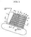
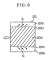
- the present invention is made of a first resin layer 2 formed in an endless shape, a base material layer 3 formed on the outer periphery of the first resin layer 2, and a second resin layer 4 including the base material layer 3.
- first resin layer 2 and the second resin layer 4 be made of rubber or elastomer and more preferably, of thermosetting polyurethane, and that the hardness thereof be selected from 80° to 98° (JIS-A). Of course, it is not necessary that the first resin layer 2 and the second resin 4 layer always have the same hardness.
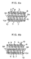
- FIGS. 2 (a) and (b) show the relationship between the yarn 5 of the inner layer A, the yarn 6 of the middle layer B, and the yarn 7 of the outer layer C.
- FIG. 2 (a) is a cross-sectional view as viewed from the plane of the line A-A of FIG. 1
- FIG. 2(b) is a cross-sectional view as viewed from the plane of the line B-B of FIG. 1.
- the yarn 5 of the inner layer A and the yarn 7 of the outer layer C functions to reinforce the belt 1 in accordance with the present invention in the direction of MD and to crimp (K) the yarn 6 of the middle layer B with the yarns 5 and 7.
- the yarn 6 of the middle layer B reinforces the belt 1 in accordance with the present invention in the direction of CMD and improves flexibility to bending at the edges of the shoe in the direction of CMD because it is crimped (K). Also, since the crimped yarn 6 of the middle layer B is positioned nearly at the center of the cross section of the base material layer 3, it stabilizes the center of bending in the direction of CMD and the obverse resin layer 2 and the reverse resin layer 4 have a function of reducing stress caused by a difference in curvature.
- the number of windings of the yarn 5 of the inner layer A and the number of windings of the yarn 7 of the outer layer C can be determined according to the size of the yarn and the strength of the yarn, or to shorten a time for winding them. Also, as shown in FIG. 3, the number of grouped (side by side) windings of yarn 5 and the number of grouped (side by side) windings of yarn 7 may be increased (to two in the drawing) in a portion 1a contacting a shoe 22 (densely hatched portion) and at the boundary portions 1c between the portion 1a and portions 1b not contacting the shoe 22. On the other hand, the number of yarn windings 5 and the number of yarn windings 7 in each grouping may be decreased (to one in the drawing) at the portions 1b not contacting the shoe 22 at both end portions of the belt I in accordance with the present invention.
- the adjustment of the number of yarn windings is also important as a means for producing base material characteristics to be required in the case where the first resin layer 2 and the second resin layer 4 are different in thickness and in bending characteristics from each other.
- the winding density (pitch) of the yarn 5 of the inner layer A and that of the yarn 7 of the outer layer 7 can suitably be determined according to the size and the strength of the yarn.
- the winding densities (pitches) of the yarns 5 and 7 may be increased in the portion 1a contacting the shoe 22 (densely batched portion) and at the boundary portions 1c between the portion 1a and the portions 1b not contacting the shoe 22 (i.e., in these areas the the interval or pitch of the windings is reduced) to produce high bending strength and tensile strength in the direction of MD.
- the densities of the yarns 5 and 7 may be decreased (the interval or pitch of the yarn is increased in these areas) in the portions 1b not contacting the shoe 22 at both end portions of the belt 1 in accordance with the present invention.
- the number and the density (pitch) of the crimped (K) yarn 6 of the middle layer B can suitably be determined according to the size and the strength of the yarn so as to ensure strength in the direction of CMD.
- the yarns 5, 6 and 7 constituting the layers A, B and C can satisfactorily be made of a synthetic fiber such as nylon, polyester, aromatic polyester having high function and high elasticity, aromatic polyamide, aromatic polyamide or polyethylene having high strength. Also, an inorganic fiber such as carbon fiber, glass fiber, or the like can be used.
- the size of the fiber (yarn) may be a monofilament or a multifilament having a diameter of 0.3 mm to 1.0 mm, or a twist yarn thereof.
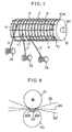
- a separating agent (not shown) is applied to the ground surface of a mandrel 8 rotatable around an axis 8a, or a separating sheet (not shown) is placed on the ground surface, and then resin is applied thereon to a thickness of about 0.5 mm to 2 mm by the use of a coater 9 (doctor bar or a coater bar) to form the first resin layer 2.
- a coater 9 doctor bar or a coater bar
- the yarn 5 is wound spirally on the first resin layer 2 in the circumferential direction to form the base material inner layer A.
- the winding pitch can be determined on an arbitrary pitch, and may be common or changed in the range in the axial direction of the mandrel 8.
- the yarn 6 is arranged on the base material inner layer A nearly parallel to the axial direction (in the direction of CMD) to form the base material middle layer B.
- ring-shaped clamps 10 are fitted on both ends in the axial direction of the mandrel 8 and retaining projections 10a formed on the ring-shaped clamps 10 are used.
- the yarn 7 is wound spirally on the base material middle layer B in the circumferential direction to form the base material outer layer C.
- the yarn 7 is wound on the yarn 6 of the middle layer B while it is being unwound from bobbins 7a and is being guided by guide rings 11, as shown in FIG. 7. It is because it is intended to wind the yarn 7 on the yarn 6 with a uniform contact force that the guide ring 11 is used. This can make the yarn 6 crimp uniformly (K).
- a resin material R is supplied to the base material layer 3 from a nozzle 12 to form the second resin layer 4.
- the second resin layer 4 penetrates the base material layer 3 and joins to the outer surface of the first resin layer 2 at a joint M.
- a primer or an adhesive be previously applied to the outer surface of the first resin layer 2.
- the belt 1 in accordance with the present invention is separated from the mandrel 8.
- the separating agent is previously applied to the surface of the mandrel 8 or the separating sheet is previously placed thereon. Also, it is also recommended that hydraulic pressure be used or the expansion or the contraction of the resin be used as a separating method.
- thermosetting urethane prepolymer: aziprene L100 made by Uniroyal Corp., curing agent 3,3' dichloro 4.4' diamino phenyl methane, 90°, JIS-A
- a polyester multifilament yarn 5 of 4000 d was wound spirally on the outer periphery of the first resin layer 2 in the direction of MD by winding 13 turns per 5 cm to form a base material inner layer A and then a Kevlar multifilament yarn 6 of 4000 d was arranged generally parallel to the shaft of the mandrel 8 by placing 10 runs per 5 cm to form the base material middle layer B.
- a polyester multifilament yarn 7 of 4000 d was wound spirally on the outer periphery of the wound yarn 6 in the direction of MD by the same number of turns as the base material inner layer A (13 turns per 5 cm) and shifted a half pitch to form the base material outer layer C.
- thermosetting urethane resin was applied to and impregnated into a base material layer 3 to form a second resin layer 4 having a thickness of about 5 mm and then the second resin layer 4 was heated and cured at 100° C or 5 hours and then was ground to a thickness of 5.5 mm, and finally, was grooved in the direction MD with rotary teeth to form a belt 1 in accordance with the present invention (Example 1).
- a first resin layer 2 was formed by using the same device and the same resin as was used in Example 1, and then two strands of polyester multifilament yarn 5 of 2000 d were wound spirally in the direction of MD by placing 26 turns (total, in groups of two) per 5 cm to form a base material inner layer A.
- a Kevlar multifilament yarn 6 of 4000 d was arranged on the inner layer A generally in parallel to the shaft of the mandrel by placing 10 pieces per 5 cm to form a base material inner layer B.
- two strands of polyester multifilament yarn 7 of 2000 d were wound spirally on the yarn 6 in the direction of MD by placing 26 turns (total, in groups of two) per 5 cm, as is the case with the base material inner layer A, being shifted a half pitch from the layer A, to form the base material outer layer C.
- thermosetting urethane resin was applied to and impregnated into the base material layer to form a second resin layer 4 having a thickness of about 5 mm, and then the second resin layer 4 was heated and cured at 100 C° for 5 hours and then was ground to a thickness of 5.5 mm, and finally, was grooved in the direction MD with rotary teeth to form a belt 1 in accordance with the present invention (Example 2).
- a first resin layer 2 was formed by using the same device and the same resin as was used in the embodiment 1, and then two strands of polyester multifilament yarn 5 of 4000 d were wound spirally in the direction of MD on the first resin layer 2 in the range of a shoe width plus 10 cm to the right and left by placing 20 turns (total, in groups of two) per 5 cm and a polyester multifilament yarn 5 of 4000 d was wound spirally in the direction of MD in portions other than the range described above, that is, in portions corresponding to the end portions of the belt end, by placing 10 turns per 5 cm to form a base material inner layer A.
- a Kevlar multifilament yarn 6 of 4000 d was arranged on the inner layer A in parallel to the shaft of the mandrel by placing 10 pieces per 5 cm to form a base material middle layer B.
- two strands of polyester multifilament yarn 6 of 4000 d were wound spirally in the direction of MD on the middle layer B in the range of a shoe width plus 10 cm to the right and left by placing 20 turns (total, in groups of two) per 5 cm, shifted a half pitch from the yarn 5 of the inner layer A, by the method used for constituting the inner layer A, and a single strand of polyester multifilament yarn of 4000 d was wound spirally in the direction of MD in portions other than the range described above, that is, in portions corresponding to the end portions of the belt, by placing 10 turns per 5 cm shifted a half pitch from the inner layer A to form the base material outer layer C.
- thermosetting urethane resin was applied to and impregnated into the base material layer 3 to form a second resin layer 4 having a thickness of about 5 mm, and then the second resin layer 4 was heated and cured at 100 C° for 5 hours and then was ground to a thickness of 5.5 mm, and finally, was grooved in the direction MD with rotary teeth to form a belt 1 in accordance with the present invention (Example 3).
- a first resin layer 2 was formed by using the same device and the same resin as was used in Example 1, and then three strands of polyester multifilament yarn 5 of 4000 d were wound spirally in the direction of MD on the first resin layer 2 at equal intervals with 15 turns (total, in groups of three) per 5 cm to form a base material inner layer A in a shorter time than in Example 1.
- a Kevlar multifilament yarn 6 of 4000 d was arranged on the inner layer A in parallel to the shaft of a mandrel with 10 pieces per 5 cm to form a base material middle layer B.
- thermosetting urethane resin was applied to and impregnated into the base material outer layer C to form a second resin layer 4 having a thickness of about 5 mm and then the second resin layer 4 was heated and cured at 100 °C for 5 hours and then was ground to a thickness of 5.5 mm, and finally, was grooved in the direction of MD with rotary teeth to produce a belt 1 in accordance with the present invention (Example 4).
- thermosetting urethane prepolymer: aziprene L100 made by Uniroyal, Corp., curing agent 3.3' dichloro 4.4' diamino phenyl methane, 90°, JIS-A
- a doctor bar arranged in parallel to the mandrel 8 to form a first resin layer 2 and the first resin layer 2 was heated and cured.
- a fabric woven in an endless shape by using polyester multifilament yarns of 4000 d as warps and wefts was wound on the first resin layer 2 and then was coated with the same thermosetting urethane resin as described above to a thickness of about 5 mm and was ground to a thickness of 5.5 mm, and then was grooved in the circumferential direction with rotary teeth to produce a comparative belt.
- the belt 1 in accordance with the present invention has a base material structure responsive to compression and tension in the direction of CMD; secondly, the flexibility of the crimped yarn of the middle layer to the bending at the shoe edge in the direction of CMD is improved by the yarn of the outer layer and the yarn of the inner layer, thirdly, since the crimped yarn of the middle layer is positioned at the center of the cross section of the base material layer, the center of bending in the direction of CMD is stabilized and hence expansion and contraction produced in the obverse and reverse resin layers by the difference in curvature between the base material layers are not concentrated only on the one side thereof.
- the present invention may have the pitches of the yarns wound in the circumferential direction of the inner layer and the outer layer constituting the base material layer change across the width of the belt. Therefore, the present invention can have the effect of improving the bending and tension characteristics of the base material not only at the portions contacting the shoe, but also at the boundary portions between the portion contacting the shoe and the end portions not contacting the shoe.
- the present invention may have the number of the yarns wound in the circumferential direction of the inner layer and the outer layer constituting the base material layer is one or more than one, it can have an effect of producing high bending strength and tension in the direction of MD by increasing the density of the yarn in the portion contacting the shoe and at the boundaries between the portion contacting the shoe and the end portions not contacting the shoe.
- the present invention may be made with a first resin layer formed on the ground surface of a mandrel, a base material inner layer formed by winding a yarn on the first resin layer spirally in the circumferential direction, a base material middle layer formed by arranging a yarn on the inner layer in nearly parallel relationship to the axial direction of the mandrel and a base material outer layer formed by winding a yarn spirally in the circumferential direction in such a way that it does not overlap the yarn of the inner layer and crimps the yarn of the middle layer, and a second resin layer formed on the base material composite layer such that it envelopes the whole composite layer. Therefore, the present invention can provide for easy manufacturing a shoe press belt which improves flexibility in bending in the direction of CMD, stabilizes the center of curvature in the direction of MD and in the direction of CMD and reduces stress to the resin.
- the present invention may have the pitches of the yarns wound in the circumferential direction of the inner layer and the outer layer constituting the base material layer change along the width of the belt, a shoe press belt capable of improving the bending and tensile strength characteristics of the base material in the portion contacting the shoe and at the boundary portions between the portion contacting the shoe and the portion not contacting the shoe can be easily manufactured.
- the present invention may be made with the number of the yarns simultaneously wound in the circumferential direction of the inner layer and the outer layer constituting the base material layer be one or more than one, manufacturing efficiency may be realized in making a shoe press belt capable of producing high bending strength and tension in the direction of MD, by increasing the density of the yarn in the portion contacting the shoe and at the boundary portions between the portion contacting the shoe and the portion not contacting the shoe.
Landscapes
- Engineering & Computer Science (AREA)
- Manufacturing & Machinery (AREA)
- Paper (AREA)
Claims (6)
- Band für eine Schuhpresse, welches eine erste Harzschicht (2), die auf einem Dorn gebildet ist, eine Basismaterialschicht (3), die auf der äußeren Peripherie der ersten Harzschicht (2) gebildet ist, und eine zweite Harzschicht (4), die die Basismaterialschicht (3) einschließt, umfaßt, dadurch gekennzeichnet, daß die Basismaterialschicht (3) aus einer Kompositschicht gebildet ist, die eine innere Schicht (A), in welcher wenigstens ein Garnstrang (5) spiralförmig auf der ersten Harzschicht (2) in der umfänglichen Richtung gewickelt ist, eine Mittelschicht (B), in welcher wenigstens ein Garnstrang (6) auf der inneren Schicht (A) nahezu parallel zu der axialen Richtung des Dorns angeordnet ist, und eine äußere Schicht (C) einschließt, in welcher wenigstens ein Garnstrang (7) spiralförmig auf der Mittelschicht (B) in der umfänglichen Richtung auf eine solche Weise gewickelt ist, daß er nicht mit dem Garn (5) der inneren Schicht (A) überlappt und das Garn (6) der Mittelschicht (B) fältelt.
- Band für eine Schuhpresse nach Anspruch 1, dadurch gekennzeichnet, daß Abstände der Garnwicklungen, die in der umfänglichen Richtung wenigstens einer der inneren Schicht und der äußeren Schicht, welche die Basismaterialschicht bilden, gewickelt sind, sich über die Breite des Bandes verändern.
- Band für eine Schuhpresse nach Anspruch 1 oder 2, dadurch gekennzeichnet, daß die Anzahl an Garnsträngen, die in der umfänglichen Richtung wenigstens einer der inneren Schicht und der äußeren Schicht, welche die Basismaterialschicht bilden, gewickelt sind, größer als 1 ist.
- Verfahren zum Herstellen eines Bandes für eine Schuhpresse, wobei das Verfahren die Schritte umfaßt: Bilden einer ersten Harzschicht (2) auf einem Dorn; Bilden einer inneren Schicht (A) eines Basismaterials (3) durch Wickeln wenigstens eines Garnstrangs (5) auf der ersten Harzschicht (2) spiralförmig in der umfänglichen Richtung; Bilden einer Mittelschicht (B) des Basismaterials durch Anordnen wenigstens eines Garnstrangs (6) auf der inneren Schicht (A) nahezu parallel zu der axialen Richtung des Dorns; Bilden einer äußeren Schicht (C) des Basismaterials durch Wickeln wenigstens eines Garnstrangs (7) spiralförmig in der umfänglichen Richtung auf eine solche Weise, daß er nicht mit dem Garn (5) der inneren Schicht (A) überlappt und das Garn (6) der Mittelschicht (B) fältelt; und Bilden einer zweiten Harzschicht (4) auf einer Basismaterialkompositschicht (3) auf eine solche Weise, daß sie die gesamte Kompositschicht einschließt.
- Verfahren zum Herstellen eines Bandes für eine Schuhprese nach Anspruch 4, dadurch gekennzeichnet, daß Abstände der Garnwicklungen, die in der umfänglichen Richtung der inneren Schicht und der äußeren Schicht, welche die Basismaterialschicht bilden, gewickelt sind, sich über die Breite des Bandes verändern.
- Verfahren zum Herstellen eines Bandes für eine Schuhpresse nach Anspruch 4 oder 5, dadurch gekennzeichnet, daß die Anzahl an Garnsträngen, die in der umfänglichen Richtung wenigstens einer der inneren Schicht und der äußeren Schicht, welche die Basismaterialschicht bilden, gewickelt sind, größer als 1 ist.
Applications Claiming Priority (2)
| Application Number | Priority Date | Filing Date | Title |
|---|---|---|---|
| JP11869099 | 1999-04-26 | ||
| JP11869099A JP3488397B2 (ja) | 1999-04-26 | 1999-04-26 | シュープレス用ベルト及びその製造方法 |
Publications (3)
| Publication Number | Publication Date |
|---|---|
| EP1055773A2 EP1055773A2 (de) | 2000-11-29 |
| EP1055773A3 EP1055773A3 (de) | 2001-03-28 |
| EP1055773B1 true EP1055773B1 (de) | 2003-10-01 |
Family
ID=14742771
Family Applications (1)
| Application Number | Title | Priority Date | Filing Date |
|---|---|---|---|
| EP00106055A Expired - Lifetime EP1055773B1 (de) | 1999-04-26 | 2000-03-29 | Band für eine Schuhpresse und Verfahren zu seiner Herstellung |
Country Status (7)
| Country | Link |
|---|---|
| US (1) | US6284102B1 (de) |
| EP (1) | EP1055773B1 (de) |
| JP (1) | JP3488397B2 (de) |
| KR (1) | KR100593868B1 (de) |
| CN (1) | CN1102495C (de) |
| CA (1) | CA2304936C (de) |
| DE (1) | DE60005597T2 (de) |
Families Citing this family (15)
| Publication number | Priority date | Publication date | Assignee | Title |
|---|---|---|---|---|
| US6908532B2 (en) * | 1999-06-01 | 2005-06-21 | Voith Sulzer Papiermaschinen Gmbh | Press belt |
| WO2002030322A2 (en) * | 2000-10-10 | 2002-04-18 | Prodesco, Inc. | Bifurcated fabric sleeve stent graft with junction region strengthening elements |
| JP2002275780A (ja) * | 2001-03-19 | 2002-09-25 | Ichikawa Woolen Textile Co Ltd | シュープレス用ベルト |
| DE50112624D1 (de) * | 2001-04-18 | 2007-07-26 | Stowe Woodward Ag | Schuhpressenbelt |
| US7014733B2 (en) * | 2002-05-14 | 2006-03-21 | Stowe Woodward L.L.C. | Belt for shoe press and shoe calender and method for forming same |
| US6989080B2 (en) * | 2003-06-19 | 2006-01-24 | Albany International Corp. | Nonwoven neutral line dryer fabric |
| US7011731B2 (en) | 2003-07-02 | 2006-03-14 | Albany International Corp. | Long nip press belt made from thermoplastic resin-impregnated fibers |
| US20050003724A1 (en) * | 2003-07-02 | 2005-01-06 | Fitzpatrick Keith | Substrate for endless belt for use in papermaking applications |
| FI122410B (fi) * | 2004-02-03 | 2012-01-13 | Tamfelt Pmc Oy | Puristinhihna |
| KR101106847B1 (ko) | 2004-03-26 | 2012-01-19 | 이치가와 가부시키가이샤 | 슈프레스용 벨트 |
| JP4524233B2 (ja) * | 2005-09-22 | 2010-08-11 | イチカワ株式会社 | シュープレス用ベルト |
| US9222208B2 (en) * | 2005-12-29 | 2015-12-29 | Albany International Corp. | Elastic silicone rubber belt |
| US8535484B2 (en) * | 2011-01-21 | 2013-09-17 | Albany International Corp. | Ultra-resilient fabric and method of making thereof |
| FI20115099L (fi) | 2011-01-31 | 2012-08-01 | Metso Fabrics Oy | Kenkäpuristinhihna, menetelmä sen valmistamiseksi ja käyttö kenkäpuristimessa |
| CN114770922B (zh) * | 2022-05-19 | 2024-07-16 | 安徽绿动能源有限公司 | 全自动换位式多纤维缠绕一体机 |
Family Cites Families (10)
| Publication number | Priority date | Publication date | Assignee | Title |
|---|---|---|---|---|
| DE3715153A1 (de) | 1987-05-07 | 1988-12-01 | Voith Gmbh J M | Verstaerkter pressmantel fuer eine presseinrichtung zur behandlung bahnfoermigen gutes, wie z. b. von papierbahnen, sowie verfahren und vorrichtung zu seiner herstellung |
| US4812185A (en) | 1987-08-07 | 1989-03-14 | Albany International Corp. | Method of making a paper machine press belt |
| US4787946A (en) | 1987-08-07 | 1988-11-29 | Albany International Corp. | Method of making a paper machine press belt |
| US4944820A (en) | 1988-04-08 | 1990-07-31 | Beloit Corporation | Method for making a blanket for an extended nip press |
| US5062924A (en) | 1988-04-08 | 1991-11-05 | Beloit Corporation | Blanket for an extended nip press with anisotropic woven base layers |
| JPH07101698B2 (ja) | 1989-07-25 | 1995-11-01 | 日本電気株式会社 | 樹脂封止型半導体装置の製造方法 |
| US5525194A (en) * | 1994-04-22 | 1996-06-11 | Tamfelt Corp. | Extended nip press belt |
| US5753085A (en) * | 1996-06-11 | 1998-05-19 | Albany International Corp. | Textile substrate for a long nip press belt |
| JP3053374B2 (ja) * | 1997-07-03 | 2000-06-19 | 市川毛織株式会社 | シュープレスベルト及びその製造法 |
| JP3408416B2 (ja) * | 1998-02-26 | 2003-05-19 | 市川毛織株式会社 | シュープレス用ベルト及びその製造法 |
-
1999
- 1999-04-26 JP JP11869099A patent/JP3488397B2/ja not_active Expired - Fee Related
-
2000
- 2000-03-24 US US09/534,798 patent/US6284102B1/en not_active Expired - Lifetime
- 2000-03-29 DE DE60005597T patent/DE60005597T2/de not_active Expired - Lifetime
- 2000-03-29 EP EP00106055A patent/EP1055773B1/de not_active Expired - Lifetime
- 2000-04-10 CA CA002304936A patent/CA2304936C/en not_active Expired - Fee Related
- 2000-04-26 KR KR1020000022083A patent/KR100593868B1/ko not_active Expired - Fee Related
- 2000-04-26 CN CN00106992A patent/CN1102495C/zh not_active Expired - Fee Related
Also Published As
| Publication number | Publication date |
|---|---|
| CN1272422A (zh) | 2000-11-08 |
| DE60005597T2 (de) | 2004-08-05 |
| KR100593868B1 (ko) | 2006-07-03 |
| EP1055773A2 (de) | 2000-11-29 |
| EP1055773A3 (de) | 2001-03-28 |
| US6284102B1 (en) | 2001-09-04 |
| CA2304936A1 (en) | 2000-10-26 |
| DE60005597D1 (de) | 2003-11-06 |
| JP3488397B2 (ja) | 2004-01-19 |
| JP2000303377A (ja) | 2000-10-31 |
| KR20000071812A (ko) | 2000-11-25 |
| CA2304936C (en) | 2007-08-07 |
| CN1102495C (zh) | 2003-03-05 |
Similar Documents
| Publication | Publication Date | Title |
|---|---|---|
| EP1055773B1 (de) | Band für eine Schuhpresse und Verfahren zu seiner Herstellung | |
| JP3096127B2 (ja) | 長ニッププレスベルト | |
| EP0939162B1 (de) | Band für eine Schuhpresse und Verfahren zu seiner Herstellung | |
| AU645879B2 (en) | Spiral construction of grooved, void-volume LNP belts | |
| AU688492C (en) | Press belt and method of manufacture | |
| JP3053374B2 (ja) | シュープレスベルト及びその製造法 | |
| RU2221097C1 (ru) | Канавчатая лента для башмачного пресса с длинной зоной зажима | |
| US7185757B2 (en) | Shoe press belt | |
| EP2028317B1 (de) | Schuhpressband | |
| US6440274B1 (en) | Shoe press belt and manufacturing method | |
| JP3415767B2 (ja) | シュープレス用ベルト及びその製造方法 | |
| EP1927695A1 (de) | Band für schuhpresse | |
| MXPA99001814A (en) | Short press band and manufact method |
Legal Events
| Date | Code | Title | Description |
|---|---|---|---|
| PUAI | Public reference made under article 153(3) epc to a published international application that has entered the european phase |
Free format text: ORIGINAL CODE: 0009012 |
|
| AK | Designated contracting states |
Kind code of ref document: A2 Designated state(s): AT BE CH CY DE DK ES FI FR GB GR IE IT LI LU MC NL PT SE |
|
| AX | Request for extension of the european patent |
Free format text: AL;LT;LV;MK;RO;SI |
|
| PUAL | Search report despatched |
Free format text: ORIGINAL CODE: 0009013 |
|
| AK | Designated contracting states |
Kind code of ref document: A3 Designated state(s): AT BE CH CY DE DK ES FI FR GB GR IE IT LI LU MC NL PT SE |
|
| AX | Request for extension of the european patent |
Free format text: AL;LT;LV;MK;RO;SI |
|
| 17P | Request for examination filed |
Effective date: 20010510 |
|
| AKX | Designation fees paid |
Free format text: DE FI SE |
|
| GRAH | Despatch of communication of intention to grant a patent |
Free format text: ORIGINAL CODE: EPIDOS IGRA |
|
| GRAS | Grant fee paid |
Free format text: ORIGINAL CODE: EPIDOSNIGR3 |
|
| GRAA | (expected) grant |
Free format text: ORIGINAL CODE: 0009210 |
|
| AK | Designated contracting states |
Kind code of ref document: B1 Designated state(s): DE FI SE |
|
| REF | Corresponds to: |
Ref document number: 60005597 Country of ref document: DE Date of ref document: 20031106 Kind code of ref document: P |
|
| REG | Reference to a national code |
Ref country code: SE Ref legal event code: TRGR |
|
| PLBE | No opposition filed within time limit |
Free format text: ORIGINAL CODE: 0009261 |
|
| STAA | Information on the status of an ep patent application or granted ep patent |
Free format text: STATUS: NO OPPOSITION FILED WITHIN TIME LIMIT |
|
| 26N | No opposition filed |
Effective date: 20040702 |
|
| PGFP | Annual fee paid to national office [announced via postgrant information from national office to epo] |
Ref country code: DE Payment date: 20160322 Year of fee payment: 17 |
|
| PGFP | Annual fee paid to national office [announced via postgrant information from national office to epo] |
Ref country code: FI Payment date: 20160309 Year of fee payment: 17 Ref country code: SE Payment date: 20160311 Year of fee payment: 17 |
|
| REG | Reference to a national code |
Ref country code: DE Ref legal event code: R119 Ref document number: 60005597 Country of ref document: DE |
|
| PG25 | Lapsed in a contracting state [announced via postgrant information from national office to epo] |
Ref country code: FI Free format text: LAPSE BECAUSE OF NON-PAYMENT OF DUE FEES Effective date: 20170329 |
|
| REG | Reference to a national code |
Ref country code: SE Ref legal event code: EUG |
|
| PG25 | Lapsed in a contracting state [announced via postgrant information from national office to epo] |
Ref country code: SE Free format text: LAPSE BECAUSE OF NON-PAYMENT OF DUE FEES Effective date: 20170330 |
|
| PG25 | Lapsed in a contracting state [announced via postgrant information from national office to epo] |
Ref country code: DE Free format text: LAPSE BECAUSE OF NON-PAYMENT OF DUE FEES Effective date: 20171003 |