EP1055785B1 - Mehrwandige Verglasungsscheibe und Verfahren zur Befestigung derselben an einem Tragwerk - Google Patents
Mehrwandige Verglasungsscheibe und Verfahren zur Befestigung derselben an einem Tragwerk Download PDFInfo
- Publication number
- EP1055785B1 EP1055785B1 EP99310092A EP99310092A EP1055785B1 EP 1055785 B1 EP1055785 B1 EP 1055785B1 EP 99310092 A EP99310092 A EP 99310092A EP 99310092 A EP99310092 A EP 99310092A EP 1055785 B1 EP1055785 B1 EP 1055785B1
- Authority
- EP
- European Patent Office
- Prior art keywords
- glazing panel
- walled
- bar
- glazing
- panel
- Prior art date
- Legal status (The legal status is an assumption and is not a legal conclusion. Google has not performed a legal analysis and makes no representation as to the accuracy of the status listed.)
- Expired - Lifetime
Links
Images



Classifications
-
- E—FIXED CONSTRUCTIONS
- E04—BUILDING
- E04C—STRUCTURAL ELEMENTS; BUILDING MATERIALS
- E04C2/00—Building elements of relatively thin form for the construction of parts of buildings, e.g. sheet materials, slabs, or panels
- E04C2/54—Slab-like translucent elements
- E04C2/543—Hollow multi-walled panels with integrated webs
-
- E—FIXED CONSTRUCTIONS
- E04—BUILDING
- E04D—ROOF COVERINGS; SKY-LIGHTS; GUTTERS; ROOF-WORKING TOOLS
- E04D3/00—Roof covering by making use of flat or curved slabs or stiff sheets
- E04D3/02—Roof covering by making use of flat or curved slabs or stiff sheets of plane slabs, slates, or sheets, or in which the cross-section is unimportant
- E04D3/06—Roof covering by making use of flat or curved slabs or stiff sheets of plane slabs, slates, or sheets, or in which the cross-section is unimportant of glass or other translucent material; Fixing means therefor
- E04D3/08—Roof covering by making use of flat or curved slabs or stiff sheets of plane slabs, slates, or sheets, or in which the cross-section is unimportant of glass or other translucent material; Fixing means therefor with metal glazing bars
-
- E—FIXED CONSTRUCTIONS
- E04—BUILDING
- E04D—ROOF COVERINGS; SKY-LIGHTS; GUTTERS; ROOF-WORKING TOOLS
- E04D3/00—Roof covering by making use of flat or curved slabs or stiff sheets
- E04D3/24—Roof covering by making use of flat or curved slabs or stiff sheets with special cross-section, e.g. with corrugations on both sides, with ribs, flanges, or the like
- E04D3/28—Roof covering by making use of flat or curved slabs or stiff sheets with special cross-section, e.g. with corrugations on both sides, with ribs, flanges, or the like of glass or other translucent material
Definitions
- the present invention relates to a glazing panel. More particularly, the present invention relates to a multi-walled glazing panel suitable for use as a roof light or like structure. The present invention also provides a method of attaching a multi-walled glazing panel to a support structure.
- roof lighting enables daylight to be effectively transmitted or admitted into buildings.
- One type of roof lighting includes at least one multi-walled glazing panel supported by a support structure, which is locatable on the roof of a building.
- Such support structures generally comprise a plurality of bar members located at either side of the multi-walled glazing panel and which are adapted to receive such panels.
- bar members are commonly referred to in the industry as glazing bars and come in various shapes and sizes. It is to be understood that such panels can be located on any part of a building or like structure.
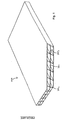
- a known type of multi-walled glazing panel 100 includes a plurality of, or at least two, horizontal sheet members 101, separated from one another by vertical interconnecting walls 102, such walls 102 defining channels 103 running along the length of the multi-walled glazing panel 100.
- multi-walled glazing panels 100 of this type are made from the extrusion of a polycarbonate material, and the thickness of such panels can range from 4 millimeters up to approximately 30 millimeters.
- a major advantage of this type of multi-walled glazing panel is that they provide good heat insulation and light transmission and consequently, can assist with savings in energy costs. Moreover, and as such glazing panels are extremely light in weight, less stress is exerted by them on the surrounding structures of the building to which they are attached and consequently, it is believed that they may actually extend the life of a building to which they are attached.
- a multi-walled glazing panel (10) attachable at either side thereof to a support structure (20,30,40), the multi-walled glazing panel (10) including a plurality of horizontal sheet members (11) separated from one another by vertical interconnecting walls (12), such vertical interconnecting walls (12) defining channels (13) running along the length of the multi-walled glazing panel (10) characterised in that each side of the multi-walled glazing panel (10) that is attachable to the support structure (20,30,40) is reinforced with at least one reinforcement bar (15) each comprising an elongate bar of rigid material, each reinforcement bar (15) being insertable into at least one of the channels (13) located adjacent the support structure (20,30,40) on each side of the glazing panel, wherein each side of the multi-walled glazing panel (10) is further provided with at least one protruding member (22,50) extending in a direction perpendicular to said horizontal sheet members that can engage with a surface of the adjacent support structure (20,30,40).
- the present invention addresses the problem outlined above.
- the sides of the multi-walled glazing panel of the present invention which are to be attached to the support structure, are reinforced by reinforcement bars, same is less likely to come free from the support structure when an object falls thereon. Therefore, it is believed that the present invention increases the overall safety of using such multi-walled glazing panels as part of a roof light or like structure.
- same acts as a mechanical restraint and moreover, enhances the inherent rigidity of the multi-walled glazing panel, thereby increasing the resistance to the dislocation of the glazing panel from the support structure.
- both of the above factors result in a high percentage of the energy of the falling object being transferred to, and absorbed by, the support structure, which can safely absorb such energy without the dislodgment of the glazing panel therefrom.
- the reinforcement means comprises a bar of metal, preferably extruded commercial grade aluminium. It is to be understood that the bar may be of any other suitable material exhibiting the desired rigidity, for example, polycarbonate.
- the reinforcement means is sized to fit snugly within a channel provided within the multi-walled glazing panel, but not too snugly so that same is difficult to insert into said channel. This has the advantage in that same is easy to locate within the glazing panel.
- the reinforcement means is of such a size that it is concealed by the portion of the support structure to which it is fixed. This has the advantage in that the reinforcement means cannot be seen from either above or below and hence, does not affect the aesthetic qualities of the glazing panel, nor hinder the transmission of light therethrough.
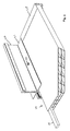
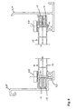
- a multi-walled polycarbonate glazing panel 10 in accordance with the present invention includes a plurality of horizontal sheet members 11, separated from one another by vertical interconnecting walls 12, such walls 12 defining channels 13 running the length of the multi-walled glazing panel 10. Additionally, and in order to reinforce the sides or side portions of the panel 10 which are to be attached or supported by a support structure, such as a glazing bar, same is further provided with reinforcement bars 15 which are insertable into channels 13 located at either side of the panel 10. For illustration purposes, only one of such bars 15 is shown in Figure 2.
- each side of the panel 10 is locatable between the jaw or clamp portion 21 of a glazing bar 20 of the interlocking type, sold by us under the name "MULTI-LINK-PANEL INTERLOCKING MODULAR GLAZING SYSTEM", which is the subject of our European Patent No. 0473321.
- the panel 10 and reinforcement bars 15 are fixed to the glazing bar 20 via fixing means 22, such as a self tapping screw, which passes through an aperture provided in a surface of the jaw 21 into the panel 10 and reinforcement bar 15.
- the bar 15 can be located in either of the channels 13 directly adjacent the glazing bar 20. Additionally, the bar 15 is located within the confines of the jaw 21 of the glazing bar 20 and hence, is concealed.
- a reinforcement bar 15 is inserted into a channel 13 at each side of the panel 10 which are to be fixed to the glazing bars 20 of a support structure. It is preferable that the length of the reinforcement bar 15 is selected such that when located within the glazing panel 10, same protrudes at both ends thereof, preferably by about 4 mm.
- a clearance hole or aperture is provided through the top of each jaw 21 and through the top layer of the glazing panel 10, followed by a tapping hole through the reinforcement bar 15.
- Such an aperture is preferably provided on both sides of the glazing panel 10 in a central position along the length of each glazing bar 20 and immediately over the center of the reinforcement bar 15.
- Fixing means 22, such as a self tapping screw is then driven into the assembly of the glazing bar 20, panel 10 and reinforcement bar 15, until the head of the screw 22 sits on the surface of the glazing bar 20.
- such screw 22 is not tightened to such an extent that free thermal movement of the glazing panel 10 is hindered, that is, when fixed to its respective glazing bar 20.
- U-profile capping members 25 are then placed at either end of the glazing panel 10.
- the protrusion of the reinforcement bar 15 beyond the end of the panel 10 is intended to act as a restraint by contact with the U-profile capping members 25, thus preventing any sideways movement of the reinforcement bar 15.
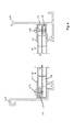
- a side of the panel 10 is locatable between a jaw or clamp portion 31 provided by a base member 35 and capping bar 34 of a glazing bar 30.
- the panel 10 and reinforcement bar 15 are fixed to the glazing bar 30 via fixing means 32, such as a self-tapping screw, which passes through an aperture provided in a surface of a upper seal 36a into the panel 10 and reinforcement bar 15.
- fixing means 32 such as a self-tapping screw, which passes through an aperture provided in a surface of a upper seal 36a into the panel 10 and reinforcement bar 15.
- the bar 15 is located in the uppermost channel 13 provided within the panel 10, however, it is understood that it can be provided in any of the channels 13. Additionally, the bar 15 is located within the confines of the jaw 31 provided by the base member 35 and capping bar 34 of the glazing bar 30 and hence, is concealed.
- each end of the glazing panel 10 can be provided with a U-profile capping member.
- a reinforcement bar 15 is inserted into a channel at each side of the panel 10 which is to be fixed to the glazing bar 30 of a support structure.
- the length of the reinforcement bar 15 is selected such that, when located within the glazing panel 10, same protrudes at both ends thereof, preferably by about 4 mm.
- a clearance hole or aperture is provided through the top of the seal 36a and through the top layer of the glazing panel 10, followed by a tapping hole through the reinforcement bar 15.
- Such an aperture is preferably provided on both sides of the glazing panel 10 in a central portion along the length of each glazing bar 30 and immediately over the centre of the reinforcement bar 15.
- Fixing means 32 such as a self-tapping screw, is then driven into the assembly of the seal 36a, panel 10 and reinforcement bar 15.
- U-profile capping members are then placed at either end of the glazing panel 10
- the protrusion of the reinforcement bar 15 beyond the ends of the panel 10 is intended to act as a restraint by contact with the U-profile capping member, thus preventing any sideway movements of the reinforcement bar 15.
- each side of the panel 10 is locatable between the jaw or clamp portion 31 provided by a base member 35 and a capping bar 34 of a glazing bar 30.
- the panel 10 and reinforcement bar 15 are fixed to one another via fixing means 32, such as a self-tapping screw.
- fixing means 32 such as a self-tapping screw.
- one end of fixing means 32 protrudes into space 38 provided by base member 35 of the glazing bar 30.
- same passes through a lower seal 36b provided on the base member 35 of the glazing bar 30.
- the fixing means 32 protrudes into the space 38, when the glazing panel 10 is hit by an object, this causes the end of the fixing means 32 to engage with a surface of the base member 35 and hence, prevents the glazing panel 10 from being removed or dislodged from the glazing bar 30.
- the reinforcement bar is located in the lowermost channel 13, it is to be understood that it can be located in any of the channels 13 adjacent the glazing bar 30. In this connection, it is only the length of the fixing means which must be long enough to engage with a surface of the glazing bar 30. For the avoidance of any doubt, such surface may be provided by the base member 35 or capping bar 34 of glazing bar 30.
- each end of the glazing panel 10 may be provided with a U-profile capping member.
- a reinforcement bar 15 is inserted into a channel 13 at each side of the panel which are to be attached to the glazing bars 30 of the support structure. It is preferable, that the lengths of the reinforcement bar 15 is selected such that when located within the glazing panel 10, same protrudes at both ends thereof, preferably by about 4 mm.
- a clearance hole or aperture is provided through the top of the glazing panel 10, followed by a tapping hole through the reinforcement bar 15.
- Such an aperture is preferably provided on both sides of the glazing panel 10 in a central position.
- Fixing means 32 such as a self-tapping screw, is then driven into a surface of the glazing panel 10 and reinforcement bar 15 until an end of same protrudes through reinforcement bar 15 into space 38 provided by base member 35 of the glazing bar 30.
- U-profile capping members can then be placed on either end of the glazing panel 10.
- the protrusion of the reinforcement bar 15 beyond the end of the panel 10 is intended to act as a restraint by contacting the U-profile capping members, thus preventing any sideways movement of the reinforcement bar 15.
- each side of the panel 10 is locatable between the jaw or clamp portion 41 provided by a base member 45 and a capping bar 44 of a glazing bar 40.
- the panel 10 and reinforcement bar 15 are fixed to one another via fixing means 42, such as a self-tapping screw.
- fixing means 42 such as a self-tapping screw.
- one end 42a of fixing means 42 protrude into space 48 provided by base member 45 of the glazing bar 40.
- the fixing means 42 protrude into the space 48, when the glazing panel 10 is hit by an object, this causes the end 42a of the fixing means 42 to engage with a surface of the base member 45 and hence, prevents the glazing panel 10 from being removed or dislodged from the clamp portion 41 provided by the base member 45 and capping member 44.
- each end of the glazing panel 10 can be provided with a U-profile capping member.
- a reinforcement bar 15 is inserted into channels 13 at each side of the panel 10. It is preferable, that the lengths of the reinforcement bar 15 is selected such that when located within the glazing panel 10, same protrudes at both ends thereof, preferably by about 4mm.
- a clearance hole or aperture is provided through the top of the glazing panel 10, followed by a tapping hole through the reinforcement bar 15.
- Such an aperture is preferably provided on both sides of the glazing panel 10 in a central position.
- Fixing means 42 such as a self-tapping screw, is then driven into a surface of the glazing panel 10 and reinforcement bar 15, until an end of same protrudes through reinforcement bar 15 until same protrudes through the other side of the glazing panel 10.
- the panel is then located on to the base member 45 such that the lower end 42a of the fixing means 32 is located in the space 48 provided thereby and the capping member 44 of the glazing bar 40 is then placed on top of the panel 10 such that the jaws 41 provided by the glazing bar 40 clamps the panel 10 in position.
- U-profile capping members can then be placed at either end of the glazing panel 10.
- the protrusion of the reinforcement bar 15 beyond the end of the panel 10 is intended to act as a restraint by contacting the U-profile capping members, thus preventing any sideway movements of the reinforcement bar.
- each channel 13 located on either side of the multi-walled glazing panel 10 is provided with a reinforcement bar 15. It will be appreciated that by increasing the number of reinforcement bars 15, the reinforcement of the glazing panel 10 is increased such that same is less likely to become dislodged from the glazing bars 20 to which it is attached, that is, in the event that a heavy object falls onto same.
- the two channels 13 directly adjacent the glazing bar 20 are each provided with a reinforcement bar 15.
- the number of reinforcement bars 15 utilized can vary depending on the number of channels 13 provided within the multi-walled glazing panels 10 which are located at either side of the multi-walled glazing panel 10, for example, a multi-walled glazing panel 10 which includes four horizontal sheet members 11 will have three channels 13 at either side thereof and consequently, each side of such a multi-walled glazing panel 10 can be provided with three reinforcement bars 15.
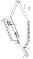
- each stop member 50 includes a plurality of downwardly extending legs 51 which, in use, are located adjacent the reinforcement bars 15 (see Figure 9). Depending on the width of the reinforcement bars 15 and the width of the channels 13, it is to be understood that the legs 51 may be inserted into the same channel 13 within which the reinforcement bar 15 is located, or in an adjacent channel 13.
- the legs 51 of the stop member 50 are long enough so that they extend into space 23 provided by glazing panel 20, such that on impact the lower portions of the legs 51 will interact or engage with the glazing bar 20 and hence, assists with preventing the multi-walled glazing panel 10 from being removed or dislodged from the glazing bar 20, that is, in the event that an object falls onto same.
- a reinforcement bar 15 is inserted into each channel 13 located at either side of the multi-walled glazing panel 10. It is preferable that the length of the reinforcement bar 15 is selected such that when located within the glazing panel 10, same protrudes at both ends thereof, preferably by about 4 mm.
- a plurality of suitably spaced clearance holes or apertures are provided through the top of each jaw 21 and through the glazing panel 10 such that the legs 51 of stop member 50 can be inserted through the jaw 21 of the glazing bar 20 and through the multi-walled glazing panel 10 located therein.
- U-profile capping members 25 are then placed at either end of the glazing panel 10.
- the protrusion of the reinforcement bar 15 beyond the end of the panel 10 is intended to act as a restraint by contact with the U-profile capping members 25, thereby preventing any sideways movement of the reinforcement bars 15.
- the sides portions, which are attachable to a support structure, of a multi-walled glazing panel in accordance with the present invention can be constructed from a solid material integral with the multi-walled glazing panel.
- the channels located within the side portion which is attachable to the support structure may be filled with a solid, settable material; the material having the desired rigidity.
- a multi-walled glazing panel in accordance with the present invention may have more than one reinforcement bar located in adjacent channels in each side portion of the multi-walled glazing panel which is to be attached to, or supported by, a support structure.
- a multi-walled glazing panel in accordance with the present invention can be located on any part of a building or other structure.
Landscapes
- Engineering & Computer Science (AREA)
- Architecture (AREA)
- Civil Engineering (AREA)
- Structural Engineering (AREA)
- Securing Of Glass Panes Or The Like (AREA)
- Joining Of Glass To Other Materials (AREA)
- Finishing Walls (AREA)
- Load-Bearing And Curtain Walls (AREA)
Claims (10)
- Mehrwandige Verglasungsscheibe (10), die ihren beiden Seiten an einer Tragstruktur (20, 30, 40) befestigbar ist, wobei die mehrwandige Verglasungsscheibe (10) eine Vielzahl von horizontalen Plattenelementen (11) umfasst, die voneinander durch vertikale Verbindungswände (12) getrennt sind, wobei die vertikalen Verbindungswände (12) Kanäle (13) definieren, die entlang der Länge der mehrwandigen Verglasungsscheibe (10) verlaufen, dadurch gekennzeichnet, dass jede Seite der mehrwandigen Verglasungsscheibe (10), die an der Tragstruktur (20, 30, 40) befestigbar ist, mit wenigstens einer Verstärkungstange (15) verstärkt ist, die jeweils eine längliche Stange aus festem oder steifen Material aufweist, wobei jede Verstärkungsstange (15) in wenigstens einen der Kanäle (13) einfügbar ist, die benachbart zur Stützstruktur (20, 30, 40) auf jeder Seite der Verglasungsscheibe angeordnet sind, wobei jede Seite der mehrwandigen Verglasungsscheibe (10) ferner mit wenigstens einem vorstehenden Element (22, 50) versehen ist, das sich in einer Richtung im rechten Winkel zu den horizontalen Plattenelementen erstreckt und das im Eingriff oder in Betätigung mit einer Oberfläche der benachbarten Tragstruktur (20, 30, 40) kommen kann.
- Mehrwandige Verglasungsscheibe nach Anspruch 1, bei der die Verstärkungsstangen (15) in wenigstens einen der Kanäle (13) einfügbar sind, die unmittelbar benachbart zur Tragstruktur (20, 30, 40) auf jeder Seite der Verglasungsscheibe angeordnet sind.
- Mehrwandige Verglasungsscheibe (10) nach Anspruch 2, wobei jeder Kanal (13), der unmittelbar benachbart zur Tragstruktur (20, 30, 40) angeordnet ist, mit einer Verstärkungsstange (15) versehen ist.
- Mehrwandige Verglasungsscheibe (10) nach einem der vorhergehenden Ansprüche, bei der die Verstärkungsstangen aus Metall oder Polykarbonat gemacht sind.
- Mehrwandige Verglasungsscheibe (10) nach einem der Ansprüche 1 bis 4, in der die Verstärkungsstangen (15) so bemessen sind, dass sie aus beiden Ende des Kanals (13) hervortreten, indem sie angeordnet sind.
- Mehrwandige Verglasungsscheibe(10) nach einem der vorhergehenden Ansprüche, bei der jedes vorspringende Element wenigstens eine Schraube (22) aufweist, die aus wenigstens einer der jeweiligen Verstärkungsstangen (15) der mehrwandigen Verglasungsscheibe (10) hervortritt.
- Mehrwandige Verglasungsscheibe nach Anspruch 6, wobei jedes vorspringende Element wenigstens ein Stopelement (50) umfasst, das bei Gebrauch benachbart zur jeweiligen Verstärkungsstange (15) anordenbar ist.
- Mehrwandige Verglasungsscheibe (10) nach Anspruch 7, bei der das Stopelement (50) wenigstens zwei Beine (51) umfasst.
- Mehrwandige Verglasungsscheibe (10) nach einem der vorhergehenden Ansprüche, bei der die Seiten der mehrwandigen Verglasungsscheibe (10) so bemessen sind, dass sie von einem Abschnitt der Tragstruktur (20, 30, 40) verdeckt sind, an der die mehrwandige Verglasungsscheibe (10) befestigt ist.
- Verfahren zur Befestigung der Seiten einer mehrwandigen Verglasungsscheibe (10), wie in einem der vorhergehenden Ansprüche beansprucht, an einer Tragstruktur, wobei das Verfahren die Schritte aufweist:Einfügen wenigstens einer Verstärkungsstange (15) in wenigstens einem Kanal, der an jeder Seite der mehrwandige Verglasungsscheibe (10) angeordnet ist; undBefestigen der mehrwandige Verglasungsscheibe (10) an der Tragstruktur (20, 30, 40), wobei es ferner den Schritt eines Versehens jeder Seite der mehrwandige Verglasungsscheibe (10) mit wenigstens einem vorspringenden Element (22, 50) aufweist, das sich in einer Richtung im rechten Winkel zu den horizontalen Plattenelementen der Verglasungsscheibe erstreckt und das mit einer Oberfläche der Tragstruktur (20, 30, 40) in Eingriff oder Betätigung kommen kann.
Priority Applications (1)
| Application Number | Priority Date | Filing Date | Title |
|---|---|---|---|
| US09/536,156 US6430893B1 (en) | 1999-05-22 | 2000-03-28 | Glazing panel |
Applications Claiming Priority (2)
| Application Number | Priority Date | Filing Date | Title |
|---|---|---|---|
| GB9911903 | 1999-05-22 | ||
| GBGB9911903.4A GB9911903D0 (en) | 1999-05-22 | 1999-05-22 | A glazing panel |
Publications (3)
| Publication Number | Publication Date |
|---|---|
| EP1055785A2 EP1055785A2 (de) | 2000-11-29 |
| EP1055785A3 EP1055785A3 (de) | 2001-05-23 |
| EP1055785B1 true EP1055785B1 (de) | 2005-03-02 |
Family
ID=10853945
Family Applications (1)
| Application Number | Title | Priority Date | Filing Date |
|---|---|---|---|
| EP99310092A Expired - Lifetime EP1055785B1 (de) | 1999-05-22 | 1999-12-15 | Mehrwandige Verglasungsscheibe und Verfahren zur Befestigung derselben an einem Tragwerk |
Country Status (4)
| Country | Link |
|---|---|
| EP (1) | EP1055785B1 (de) |
| AT (1) | ATE290140T1 (de) |
| DE (1) | DE69923952D1 (de) |
| GB (1) | GB9911903D0 (de) |
Cited By (1)
| Publication number | Priority date | Publication date | Assignee | Title |
|---|---|---|---|---|
| US8568860B2 (en) | 2007-11-12 | 2013-10-29 | Sabic Innovative Plastics Ip B.V. | Multiwall polymer sheet comprising branched polycarbonate |
Families Citing this family (1)
| Publication number | Priority date | Publication date | Assignee | Title |
|---|---|---|---|---|
| GB2453864B (en) * | 2007-10-17 | 2012-06-20 | Kingspan Res & Dev Ltd | A translucent panel |
Family Cites Families (3)
| Publication number | Priority date | Publication date | Assignee | Title |
|---|---|---|---|---|
| IT8023606U1 (it) * | 1980-12-11 | 1982-06-11 | Macoplast M R S R L | Lastra in policarbonato, provvista di elementi di irrigidimento |
| GB9017768D0 (en) * | 1990-08-14 | 1990-09-26 | Danzig Barry Van | Glazing bar |
| DK111694A (da) * | 1994-09-28 | 1996-03-29 | Plastmo As | Panel af ekstruderede profilelementer |
-
1999
- 1999-05-22 GB GBGB9911903.4A patent/GB9911903D0/en not_active Ceased
- 1999-12-15 EP EP99310092A patent/EP1055785B1/de not_active Expired - Lifetime
- 1999-12-15 DE DE69923952T patent/DE69923952D1/de not_active Expired - Lifetime
- 1999-12-15 AT AT99310092T patent/ATE290140T1/de not_active IP Right Cessation
Cited By (1)
| Publication number | Priority date | Publication date | Assignee | Title |
|---|---|---|---|---|
| US8568860B2 (en) | 2007-11-12 | 2013-10-29 | Sabic Innovative Plastics Ip B.V. | Multiwall polymer sheet comprising branched polycarbonate |
Also Published As
| Publication number | Publication date |
|---|---|
| EP1055785A2 (de) | 2000-11-29 |
| EP1055785A3 (de) | 2001-05-23 |
| ATE290140T1 (de) | 2005-03-15 |
| GB9911903D0 (en) | 1999-07-21 |
| DE69923952D1 (de) | 2005-04-07 |
Similar Documents
| Publication | Publication Date | Title |
|---|---|---|
| EP1338719B1 (de) | Verkleidungssystem für Fassaden von Bauwerken | |
| CA1301220C (en) | Scaffolding platform | |
| US5755070A (en) | Multi veneer anchor structural assembly and drywall construction system | |
| GB2172626A (en) | Outer roof skin supporting system | |
| US6128883A (en) | Brick anchor system | |
| US20040003564A1 (en) | Structural walls and construction method | |
| US5355642A (en) | Prefabricated post with dual mounting members | |
| WO2015061113A1 (en) | Solar panel tile roof mounting device and method | |
| US6079174A (en) | Wall panel having movable cap | |
| EP0210042A1 (de) | Befestigung für Aushängeschilder | |
| US6430893B1 (en) | Glazing panel | |
| EP1055785B1 (de) | Mehrwandige Verglasungsscheibe und Verfahren zur Befestigung derselben an einem Tragwerk | |
| CA2142495A1 (en) | Bracket for supporting fence posts | |
| US20020100248A1 (en) | Suspended ceiling assembly | |
| CA2759778C (en) | Brick anchor system | |
| EP0553880A2 (de) | Aufhängung für Aussen-Wärmeaustauscher | |
| WO2002057557A1 (en) | A joist hanger | |
| CA2007858A1 (en) | Fixing device for cladding elements | |
| US4709887A (en) | Highway cable clamp | |
| CA2591687A1 (en) | Brick anchor system | |
| AU2020100272B4 (en) | Twist resistant roof structure | |
| US10961715B2 (en) | Twist resistant roof structure | |
| AU2019100456A4 (en) | Twist resistant roof structure | |
| KR0131396Y1 (ko) | 낙하물 차단용 안전장치 | |
| WO2003016652A8 (en) | Sub-structure for a roof or a facade |
Legal Events
| Date | Code | Title | Description |
|---|---|---|---|
| PUAI | Public reference made under article 153(3) epc to a published international application that has entered the european phase |
Free format text: ORIGINAL CODE: 0009012 |
|
| AK | Designated contracting states |
Kind code of ref document: A2 Designated state(s): AT BE CH CY DE DK ES FI FR GB GR IE IT LI LU MC NL PT SE |
|
| AX | Request for extension of the european patent |
Free format text: AL;LT;LV;MK;RO;SI |
|
| PUAL | Search report despatched |
Free format text: ORIGINAL CODE: 0009013 |
|
| AK | Designated contracting states |
Kind code of ref document: A3 Designated state(s): AT BE CH CY DE DK ES FI FR GB GR IE IT LI LU MC NL PT SE |
|
| AX | Request for extension of the european patent |
Free format text: AL;LT;LV;MK;RO;SI |
|
| RIC1 | Information provided on ipc code assigned before grant |
Free format text: 7E 04D 3/08 A, 7E 04D 3/14 B, 7E 04D 3/28 B, 7E 04C 2/54 B |
|
| 17P | Request for examination filed |
Effective date: 20011117 |
|
| AKX | Designation fees paid |
Free format text: AT BE CH CY DE DK ES FI FR GB GR IE IT LI LU MC NL PT SE |
|
| AXX | Extension fees paid |
Free format text: SI PAYMENT 20011117 |
|
| 17Q | First examination report despatched |
Effective date: 20031212 |
|
| GRAP | Despatch of communication of intention to grant a patent |
Free format text: ORIGINAL CODE: EPIDOSNIGR1 |
|
| RIC1 | Information provided on ipc code assigned before grant |
Ipc: 7E 04D 3/06 B Ipc: 7E 04D 3/36 B Ipc: 7E 04C 2/54 B Ipc: 7E 04D 3/28 B Ipc: 7E 04D 3/14 B Ipc: 7E 04D 3/08 A |
|
| RTI1 | Title (correction) |
Free format text: MULTI-WALLED GLAZING PANEL, AND METHOD OF ATTACHING IT TO A SUPPORT STRUCTURE |
|
| RIC1 | Information provided on ipc code assigned before grant |
Ipc: 7E 04D 3/06 B Ipc: 7E 04D 3/36 B Ipc: 7E 04C 2/54 B Ipc: 7E 04D 3/28 B Ipc: 7E 04D 3/14 B Ipc: 7E 04D 3/08 A |
|
| GRAS | Grant fee paid |
Free format text: ORIGINAL CODE: EPIDOSNIGR3 |
|
| GRAA | (expected) grant |
Free format text: ORIGINAL CODE: 0009210 |
|
| AK | Designated contracting states |
Kind code of ref document: B1 Designated state(s): AT BE CH CY DE DK ES FI FR GB GR IE IT LI LU MC NL PT SE |
|
| AX | Request for extension of the european patent |
Extension state: SI |
|
| PG25 | Lapsed in a contracting state [announced via postgrant information from national office to epo] |
Ref country code: NL Free format text: LAPSE BECAUSE OF FAILURE TO SUBMIT A TRANSLATION OF THE DESCRIPTION OR TO PAY THE FEE WITHIN THE PRESCRIBED TIME-LIMIT Effective date: 20050302 Ref country code: LI Free format text: LAPSE BECAUSE OF FAILURE TO SUBMIT A TRANSLATION OF THE DESCRIPTION OR TO PAY THE FEE WITHIN THE PRESCRIBED TIME-LIMIT Effective date: 20050302 Ref country code: IT Free format text: LAPSE BECAUSE OF FAILURE TO SUBMIT A TRANSLATION OF THE DESCRIPTION OR TO PAY THE FEE WITHIN THE PRE;WARNING: LAPSES OF ITALIAN PATENTS WITH EFFECTIVE DATE BEFORE 2007 MAY HAVE OCCURRED AT ANY TIME BEFORE 2007. THE CORRECT EFFECTIVE DATE MAY BE DIFFERENT FROM THE ONE RECORDED.SCRIBED TIME-LIMIT Effective date: 20050302 Ref country code: FR Free format text: LAPSE BECAUSE OF NON-PAYMENT OF DUE FEES Effective date: 20050302 Ref country code: FI Free format text: LAPSE BECAUSE OF FAILURE TO SUBMIT A TRANSLATION OF THE DESCRIPTION OR TO PAY THE FEE WITHIN THE PRESCRIBED TIME-LIMIT Effective date: 20050302 Ref country code: CH Free format text: LAPSE BECAUSE OF FAILURE TO SUBMIT A TRANSLATION OF THE DESCRIPTION OR TO PAY THE FEE WITHIN THE PRESCRIBED TIME-LIMIT Effective date: 20050302 Ref country code: BE Free format text: LAPSE BECAUSE OF FAILURE TO SUBMIT A TRANSLATION OF THE DESCRIPTION OR TO PAY THE FEE WITHIN THE PRESCRIBED TIME-LIMIT Effective date: 20050302 Ref country code: AT Free format text: LAPSE BECAUSE OF FAILURE TO SUBMIT A TRANSLATION OF THE DESCRIPTION OR TO PAY THE FEE WITHIN THE PRESCRIBED TIME-LIMIT Effective date: 20050302 |
|
| REG | Reference to a national code |
Ref country code: GB Ref legal event code: FG4D |
|
| REG | Reference to a national code |
Ref country code: CH Ref legal event code: EP |
|
| REG | Reference to a national code |
Ref country code: IE Ref legal event code: FG4D |
|
| REF | Corresponds to: |
Ref document number: 69923952 Country of ref document: DE Date of ref document: 20050407 Kind code of ref document: P |
|
| PG25 | Lapsed in a contracting state [announced via postgrant information from national office to epo] |
Ref country code: GR Free format text: LAPSE BECAUSE OF FAILURE TO SUBMIT A TRANSLATION OF THE DESCRIPTION OR TO PAY THE FEE WITHIN THE PRESCRIBED TIME-LIMIT Effective date: 20050602 Ref country code: DK Free format text: LAPSE BECAUSE OF FAILURE TO SUBMIT A TRANSLATION OF THE DESCRIPTION OR TO PAY THE FEE WITHIN THE PRESCRIBED TIME-LIMIT Effective date: 20050602 |
|
| PG25 | Lapsed in a contracting state [announced via postgrant information from national office to epo] |
Ref country code: DE Free format text: LAPSE BECAUSE OF FAILURE TO SUBMIT A TRANSLATION OF THE DESCRIPTION OR TO PAY THE FEE WITHIN THE PRESCRIBED TIME-LIMIT Effective date: 20050603 |
|
| PG25 | Lapsed in a contracting state [announced via postgrant information from national office to epo] |
Ref country code: ES Free format text: LAPSE BECAUSE OF FAILURE TO SUBMIT A TRANSLATION OF THE DESCRIPTION OR TO PAY THE FEE WITHIN THE PRESCRIBED TIME-LIMIT Effective date: 20050613 |
|
| PG25 | Lapsed in a contracting state [announced via postgrant information from national office to epo] |
Ref country code: PT Free format text: LAPSE BECAUSE OF FAILURE TO SUBMIT A TRANSLATION OF THE DESCRIPTION OR TO PAY THE FEE WITHIN THE PRESCRIBED TIME-LIMIT Effective date: 20050817 |
|
| NLV1 | Nl: lapsed or annulled due to failure to fulfill the requirements of art. 29p and 29m of the patents act | ||
| REG | Reference to a national code |
Ref country code: CH Ref legal event code: PL |
|
| PG25 | Lapsed in a contracting state [announced via postgrant information from national office to epo] |
Ref country code: IE Free format text: LAPSE BECAUSE OF NON-PAYMENT OF DUE FEES Effective date: 20051215 Ref country code: CY Free format text: LAPSE BECAUSE OF FAILURE TO SUBMIT A TRANSLATION OF THE DESCRIPTION OR TO PAY THE FEE WITHIN THE PRESCRIBED TIME-LIMIT Effective date: 20051215 |
|
| PG25 | Lapsed in a contracting state [announced via postgrant information from national office to epo] |
Ref country code: MC Free format text: LAPSE BECAUSE OF NON-PAYMENT OF DUE FEES Effective date: 20051231 Ref country code: LU Free format text: LAPSE BECAUSE OF NON-PAYMENT OF DUE FEES Effective date: 20051231 |
|
| PLBE | No opposition filed within time limit |
Free format text: ORIGINAL CODE: 0009261 |
|
| STAA | Information on the status of an ep patent application or granted ep patent |
Free format text: STATUS: NO OPPOSITION FILED WITHIN TIME LIMIT |
|
| 26N | No opposition filed |
Effective date: 20051205 |
|
| EN | Fr: translation not filed | ||
| REG | Reference to a national code |
Ref country code: IE Ref legal event code: MM4A |
|
| PG25 | Lapsed in a contracting state [announced via postgrant information from national office to epo] |
Ref country code: SE Free format text: LAPSE BECAUSE OF FAILURE TO SUBMIT A TRANSLATION OF THE DESCRIPTION OR TO PAY THE FEE WITHIN THE PRESCRIBED TIME-LIMIT Effective date: 20050602 |
|
| PGFP | Annual fee paid to national office [announced via postgrant information from national office to epo] |
Ref country code: GB Payment date: 20101001 Year of fee payment: 12 |
|
| GBPC | Gb: european patent ceased through non-payment of renewal fee |
Effective date: 20121215 |
|
| PG25 | Lapsed in a contracting state [announced via postgrant information from national office to epo] |
Ref country code: GB Free format text: LAPSE BECAUSE OF NON-PAYMENT OF DUE FEES Effective date: 20121215 |