EP1055802A2 - Drehschieber zur Ladungssteuerung einer Brennkraftmaschine - Google Patents
Drehschieber zur Ladungssteuerung einer Brennkraftmaschine Download PDFInfo
- Publication number
- EP1055802A2 EP1055802A2 EP00109397A EP00109397A EP1055802A2 EP 1055802 A2 EP1055802 A2 EP 1055802A2 EP 00109397 A EP00109397 A EP 00109397A EP 00109397 A EP00109397 A EP 00109397A EP 1055802 A2 EP1055802 A2 EP 1055802A2
- Authority
- EP
- European Patent Office
- Prior art keywords
- rotary valve
- rotary
- slide valve
- bypass
- control opening
- Prior art date
- Legal status (The legal status is an assumption and is not a legal conclusion. Google has not performed a legal analysis and makes no representation as to the accuracy of the status listed.)
- Granted
Links
- 238000002485 combustion reaction Methods 0.000 title claims abstract description 10
- 238000007789 sealing Methods 0.000 claims abstract description 8
- 230000007704 transition Effects 0.000 description 2
- 238000010276 construction Methods 0.000 description 1
- 230000002093 peripheral effect Effects 0.000 description 1
- 238000011144 upstream manufacturing Methods 0.000 description 1
Images
Classifications
-
- F—MECHANICAL ENGINEERING; LIGHTING; HEATING; WEAPONS; BLASTING
- F01—MACHINES OR ENGINES IN GENERAL; ENGINE PLANTS IN GENERAL; STEAM ENGINES
- F01L—CYCLICALLY OPERATING VALVES FOR MACHINES OR ENGINES
- F01L7/00—Rotary or oscillatory slide valve-gear or valve arrangements
- F01L7/02—Rotary or oscillatory slide valve-gear or valve arrangements with cylindrical, sleeve, or part-annularly shaped valves
- F01L7/026—Rotary or oscillatory slide valve-gear or valve arrangements with cylindrical, sleeve, or part-annularly shaped valves with two or more rotary valves, their rotational axes being parallel, e.g. 4-stroke
-
- F—MECHANICAL ENGINEERING; LIGHTING; HEATING; WEAPONS; BLASTING
- F01—MACHINES OR ENGINES IN GENERAL; ENGINE PLANTS IN GENERAL; STEAM ENGINES
- F01L—CYCLICALLY OPERATING VALVES FOR MACHINES OR ENGINES
- F01L7/00—Rotary or oscillatory slide valve-gear or valve arrangements
- F01L7/02—Rotary or oscillatory slide valve-gear or valve arrangements with cylindrical, sleeve, or part-annularly shaped valves
- F01L7/021—Rotary or oscillatory slide valve-gear or valve arrangements with cylindrical, sleeve, or part-annularly shaped valves with one rotary valve
-
- F—MECHANICAL ENGINEERING; LIGHTING; HEATING; WEAPONS; BLASTING
- F01—MACHINES OR ENGINES IN GENERAL; ENGINE PLANTS IN GENERAL; STEAM ENGINES
- F01L—CYCLICALLY OPERATING VALVES FOR MACHINES OR ENGINES
- F01L7/00—Rotary or oscillatory slide valve-gear or valve arrangements
- F01L7/16—Sealing or packing arrangements specially therefor
-
- Y—GENERAL TAGGING OF NEW TECHNOLOGICAL DEVELOPMENTS; GENERAL TAGGING OF CROSS-SECTIONAL TECHNOLOGIES SPANNING OVER SEVERAL SECTIONS OF THE IPC; TECHNICAL SUBJECTS COVERED BY FORMER USPC CROSS-REFERENCE ART COLLECTIONS [XRACs] AND DIGESTS
- Y02—TECHNOLOGIES OR APPLICATIONS FOR MITIGATION OR ADAPTATION AGAINST CLIMATE CHANGE
- Y02T—CLIMATE CHANGE MITIGATION TECHNOLOGIES RELATED TO TRANSPORTATION
- Y02T10/00—Road transport of goods or passengers
- Y02T10/10—Internal combustion engine [ICE] based vehicles
- Y02T10/12—Improving ICE efficiencies
Definitions
- the invention relates to a preamble of claim 1 Rotary valve for charge control of an internal combustion engine, the one with Control opening sections of an inlet channel connecting rotary valve with a Sealing arrangement cooperates.
- Such a rotary valve is known for example from US 4, 606 309, wherein the sealing arrangement cooperating with the rotary valve, the rotary valve seals against the inlet duct with the advantage that it is used for series engines a suitable idle speed can be achieved.
- the disadvantage here is that with a rotation of the rotary valve from the closed Position even with small changes in angle, large cross sections in the inlet duct are released, whereby a stable idle speed control of Series internal combustion engines due to the steep progression of the free cross-section above the adjustment angle of the rotary valve is not possible.
- the invention has for its object to the generic rotary valve To achieve a stable idling of the internal combustion engine to improve accordingly.
- the advantage of the invention is that a separate for the inflow of idle air Cross section is released, the control opening remains closed and the associated rapidly increasing cross-sectional growth for an unstable Idling is avoided.
- the bypass is with the control opening via an interrupted control edge of the rotary valve in Connection.
- the sealing arrangement in the upstream Section of the inlet duct is arranged, wherein the bypass in the idle position of the Rotary valve with the downstream section of the inlet channel with a the control opening related peripheral gap between rotary valve and a rotary valve housing is connected to idle air.
- the advantage of this configuration is a smooth transition from idle operation for load operation of the internal combustion engine.
- the invention also opens up the possibility that the bypass from the Control opening is arranged separately in the rotary valve, in a further embodiment the separate bypass in the idle position of a roller or ball rotary valve over a circumferential gap between the rotary valve and a rotary valve housing with a downstream section of the inlet duct leading in air Connection is established.
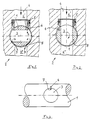
- a rotary valve 1 of an internal combustion engine 2 serves the Charge control or the throttling of the filling, the one with a control opening 3 sections 4 'and 4' 'of an inlet channel 4 connecting rotary valve 1 with a sealing arrangement 5 cooperates.
- bypass 6 is preferably a roller or spherical rotary valve 1 for controlling an inlet channel 4 with a circular Cross section in its inflow-side section 4 'an annular sealing arrangement 5 arranged, the bypass 6 in the idle position of the rotary valve 1 according to FIG. 1 with the control opening 3 closed with the outflow-side section 4 '' of the inlet duct 4 via a connection to the control opening 3 standing circumferential gap 8 between rotary valve 1 and a rotary valve housing 9 idle air is connected according to arrows B.
- the bypass can be separated from the control opening in the Rotary valve be arranged, the separate bypass in the idle position a rotary or ball rotary valve over a circumferential gap between the rotary valve and a rotary valve housing with a downstream section of the inlet duct communicates with air.
- idle air bypass arranged according to the invention in one preferably roller-shaped rotary valve it is advantageously possible without additional Components and devices, e.g. a separate idle speed control system, to achieve stable idle control of an internal combustion engine, with costs, Construction effort and space requirements are reduced.
Landscapes
- Engineering & Computer Science (AREA)
- Mechanical Engineering (AREA)
- General Engineering & Computer Science (AREA)
- Control Of Throttle Valves Provided In The Intake System Or In The Exhaust System (AREA)
- Taps Or Cocks (AREA)
- Electrical Control Of Air Or Fuel Supplied To Internal-Combustion Engine (AREA)
Abstract
Description
- Figur 1
- einen Drehschieber in Leerlaufstellung,
- Figur 2
- diesen Drehschieber in Vollast-Stellung und
- Figur 3
- den Drehschieber in Draufsicht.
Claims (5)
- Drehschieber zur Ladungssteuerung einer Brennkraftmaschine,wobei der mit einer Steueröffnung (3) Abschnitte (4', 4'') eines Einlaßkanals (4) verbindende Drehschieber (1) mit einer Abdichtanordnung (5) zusammenwirkt,
dadurch gekennzeichnet,daß der Steueröffnung (3) im Drehschieber (1) ein Leerlaufluft-Bypass (6) zugeordnet ist. - Drehschieber nach Anspruch 1, dadurch gekennzeichnet, daß der Bypass von der Steueröffnung getrennt im Drehschieber angeordnet ist.
- Drehschieber nach Anspruch 1, dadurch gekennzeichnet, daß der Bypass (6) mit der Steueröffnung (3) über eine unterbrochen ausgebildete Steuerkante (7) des Drehschiebers (1) in Verbindung steht.
- Drehschieber nach Anspruch 3, dadurch gekennzeichnet,daß bei einem Walzen- oder Kugel-Drehschieber (1) die Abdichtanordnung (5) im zuströmseitigen Abschnitt (4') des Einlaßkanals (4) angeordnet ist, wobeider Bypass (6) in Leerlaufstellung des Drehschiebers (1) mit dem abströmseitigen Abschnitt (4'') des Einlaßkanals (4) über einen mit der Steueröffnung (3) in Verbindung stehenden Umfangsspalt (8) zwischen Drehschieber (1) und einem Drehschieber-Gehäuse (9) leerlaufluftführend verbunden ist.
- Drehschieber nach Anspruch 2, dadurch gekennzeichnet, daß der gesonderte Bypass in Leerlaufstellung eines Walzen- oder Kugel-Drehschiebers über einen Umfangsspalt zwischen Drehschieber und einem Drehschieber-Gehäuse mit einem abströmseitigen Abschnitt des Einlaßkanals luftführend in Verbindung steht.
Applications Claiming Priority (2)
| Application Number | Priority Date | Filing Date | Title |
|---|---|---|---|
| DE19924396 | 1999-05-27 | ||
| DE19924396A DE19924396A1 (de) | 1999-05-27 | 1999-05-27 | Drehschieber zur Ladungssteuerung einer Brennkraftmaschine |
Publications (3)
| Publication Number | Publication Date |
|---|---|
| EP1055802A2 true EP1055802A2 (de) | 2000-11-29 |
| EP1055802A3 EP1055802A3 (de) | 2001-05-09 |
| EP1055802B1 EP1055802B1 (de) | 2004-12-15 |
Family
ID=7909412
Family Applications (1)
| Application Number | Title | Priority Date | Filing Date |
|---|---|---|---|
| EP00109397A Expired - Lifetime EP1055802B1 (de) | 1999-05-27 | 2000-05-03 | Drehschieber zur Ladungssteuerung einer Brennkraftmaschine |
Country Status (2)
| Country | Link |
|---|---|
| EP (1) | EP1055802B1 (de) |
| DE (2) | DE19924396A1 (de) |
Cited By (2)
| Publication number | Priority date | Publication date | Assignee | Title |
|---|---|---|---|---|
| EP1281839A3 (de) * | 2001-07-31 | 2003-07-02 | Bayerische Motoren Werke Aktiengesellschaft | Walzenschieber-Anordnung, insbesondere zur Ladungssteuerung einer Brennkraftmaschine |
| EP2213850A1 (de) * | 2009-01-30 | 2010-08-04 | Audi Ag | Dichtungsanordnung für einen Drehschieber |
Citations (1)
| Publication number | Priority date | Publication date | Assignee | Title |
|---|---|---|---|---|
| US4606309A (en) | 1982-07-27 | 1986-08-19 | Elf France | Device for controlling the combustion chambers exhaust and/or intake for internal combustion engines |
Family Cites Families (7)
| Publication number | Priority date | Publication date | Assignee | Title |
|---|---|---|---|---|
| US3192914A (en) * | 1963-02-25 | 1965-07-06 | Kopczyk Thomas | Power and pumping apparatus |
| JPS60153412A (ja) * | 1984-01-20 | 1985-08-12 | Mitsubishi Motors Corp | 内燃機関 |
| FR2587755B1 (fr) * | 1985-09-24 | 1988-01-22 | Negre Guy | Procede et dispositif de controle d'un circuit de gaz d'echappement de moteur a distribution rotative |
| US4658776A (en) * | 1986-02-03 | 1987-04-21 | Coman Clyde R | Rotary valve internal combustion engine |
| DE4445412C2 (de) * | 1994-12-20 | 1998-11-12 | Opel Adam Ag | Einlaßkanalsystem für eine fremdgezündete Brennkraftmaschine mit mindestens zwei in einem Zylinderkopf angeordneten Hub-Einlaßventilen pro Zylinder |
| DE19626857A1 (de) * | 1996-07-04 | 1998-01-15 | Michael Eschengerd | Drehschiebersteuerung für den Gaswechselvorgang bei Verbrennungsmotoren |
| DE19815739A1 (de) * | 1998-04-08 | 1999-10-14 | Bayerische Motoren Werke Ag | Walzenschieber-Anordnung |
-
1999
- 1999-05-27 DE DE19924396A patent/DE19924396A1/de not_active Withdrawn
-
2000
- 2000-05-03 EP EP00109397A patent/EP1055802B1/de not_active Expired - Lifetime
- 2000-05-03 DE DE50008939T patent/DE50008939D1/de not_active Expired - Lifetime
Patent Citations (1)
| Publication number | Priority date | Publication date | Assignee | Title |
|---|---|---|---|---|
| US4606309A (en) | 1982-07-27 | 1986-08-19 | Elf France | Device for controlling the combustion chambers exhaust and/or intake for internal combustion engines |
Cited By (2)
| Publication number | Priority date | Publication date | Assignee | Title |
|---|---|---|---|---|
| EP1281839A3 (de) * | 2001-07-31 | 2003-07-02 | Bayerische Motoren Werke Aktiengesellschaft | Walzenschieber-Anordnung, insbesondere zur Ladungssteuerung einer Brennkraftmaschine |
| EP2213850A1 (de) * | 2009-01-30 | 2010-08-04 | Audi Ag | Dichtungsanordnung für einen Drehschieber |
Also Published As
| Publication number | Publication date |
|---|---|
| DE50008939D1 (de) | 2005-01-20 |
| EP1055802A3 (de) | 2001-05-09 |
| DE19924396A1 (de) | 2000-11-30 |
| EP1055802B1 (de) | 2004-12-15 |
Similar Documents
| Publication | Publication Date | Title |
|---|---|---|
| DE69505763T2 (de) | Ansaugrohr mit Schwenkklappen für eine Brennkraftmaschine | |
| EP1418006A2 (de) | Zyklonabscheider | |
| DE2164992A1 (de) | Ansaugleitungssystem | |
| EP0771941B1 (de) | Zylinderkopf für Brennkraftmaschine | |
| EP1273786B2 (de) | Umschalteinrichtung zur Abgasrückführung bei einer Brennkraftmaschine | |
| DE102009007574A1 (de) | Klappenteller-Einrichtung zum Öffnen und Schließen eines Wastegate-Kanals eines Turboladers | |
| DE60203475T2 (de) | Drosselklappe und Drossel | |
| WO2000005500A1 (de) | Kraftstoffeinspritzventil für brennkraftmaschinen | |
| DE4311744C2 (de) | Ansaugrohr einer Verbrennungskraftmaschine | |
| EP1055802A2 (de) | Drehschieber zur Ladungssteuerung einer Brennkraftmaschine | |
| DE2648540C3 (de) | Geräuscharmes Hubventil | |
| DE4011292C2 (de) | Zylinderkopf für eine Brennkraftmaschine | |
| DE10032740A1 (de) | Luftansaugvorrichtung für eine Brennkraftmaschine | |
| EP1388652B1 (de) | Ansaugkanalsystem | |
| WO2007140835A1 (de) | Turboverdichter für eine brennkraftmaschine | |
| DE10065365B4 (de) | Ansaugsystem | |
| DE19814187B4 (de) | Ansaugkanal für eine Verbrennungskraftmaschine | |
| EP1035312A2 (de) | Drosselklappenstutzen zum Steuern der Leistung einer Brennkraftmaschine | |
| DE10232341A1 (de) | Vergaser | |
| DE4104010A1 (de) | Drosselklappe | |
| EP1498589A2 (de) | Luftansaugkanalsystem für Verbrennungskraftmaschinen | |
| DE19526241B4 (de) | Lufteinlaßkanalsystem für Brennkraftmaschinen | |
| DE102004002641B4 (de) | Modulare Ansaugvorrichtung | |
| DE29612018U1 (de) | Abgasrückführungsventil | |
| DE19732344A1 (de) | Drosselklappenstutzen |
Legal Events
| Date | Code | Title | Description |
|---|---|---|---|
| PUAI | Public reference made under article 153(3) epc to a published international application that has entered the european phase |
Free format text: ORIGINAL CODE: 0009012 |
|
| AK | Designated contracting states |
Kind code of ref document: A2 Designated state(s): DE FR GB IT |
|
| AX | Request for extension of the european patent |
Free format text: AL;LT;LV;MK;RO;SI |
|
| PUAL | Search report despatched |
Free format text: ORIGINAL CODE: 0009013 |
|
| AK | Designated contracting states |
Kind code of ref document: A3 Designated state(s): AT BE CH CY DE DK ES FI FR GB GR IE IT LI LU MC NL PT SE |
|
| AX | Request for extension of the european patent |
Free format text: AL;LT;LV;MK;RO;SI |
|
| 17P | Request for examination filed |
Effective date: 20011019 |
|
| AKX | Designation fees paid |
Free format text: DE FR GB IT |
|
| 17Q | First examination report despatched |
Effective date: 20040202 |
|
| GRAP | Despatch of communication of intention to grant a patent |
Free format text: ORIGINAL CODE: EPIDOSNIGR1 |
|
| GRAS | Grant fee paid |
Free format text: ORIGINAL CODE: EPIDOSNIGR3 |
|
| GRAA | (expected) grant |
Free format text: ORIGINAL CODE: 0009210 |
|
| AK | Designated contracting states |
Kind code of ref document: B1 Designated state(s): DE FR GB IT |
|
| REG | Reference to a national code |
Ref country code: GB Ref legal event code: FG4D Free format text: NOT ENGLISH |
|
| GBT | Gb: translation of ep patent filed (gb section 77(6)(a)/1977) |
Effective date: 20041215 |
|
| REF | Corresponds to: |
Ref document number: 50008939 Country of ref document: DE Date of ref document: 20050120 Kind code of ref document: P |
|
| PLBE | No opposition filed within time limit |
Free format text: ORIGINAL CODE: 0009261 |
|
| STAA | Information on the status of an ep patent application or granted ep patent |
Free format text: STATUS: NO OPPOSITION FILED WITHIN TIME LIMIT |
|
| ET | Fr: translation filed | ||
| 26N | No opposition filed |
Effective date: 20050916 |
|
| PGFP | Annual fee paid to national office [announced via postgrant information from national office to epo] |
Ref country code: FR Payment date: 20110610 Year of fee payment: 12 |
|
| PGFP | Annual fee paid to national office [announced via postgrant information from national office to epo] |
Ref country code: GB Payment date: 20110526 Year of fee payment: 12 |
|
| PGFP | Annual fee paid to national office [announced via postgrant information from national office to epo] |
Ref country code: IT Payment date: 20110527 Year of fee payment: 12 |
|
| PGFP | Annual fee paid to national office [announced via postgrant information from national office to epo] |
Ref country code: DE Payment date: 20110618 Year of fee payment: 12 |
|
| GBPC | Gb: european patent ceased through non-payment of renewal fee |
Effective date: 20120503 |
|
| PG25 | Lapsed in a contracting state [announced via postgrant information from national office to epo] |
Ref country code: IT Free format text: LAPSE BECAUSE OF NON-PAYMENT OF DUE FEES Effective date: 20120503 |
|
| REG | Reference to a national code |
Ref country code: FR Ref legal event code: ST Effective date: 20130131 |
|
| REG | Reference to a national code |
Ref country code: DE Ref legal event code: R119 Ref document number: 50008939 Country of ref document: DE Effective date: 20121201 |
|
| PG25 | Lapsed in a contracting state [announced via postgrant information from national office to epo] |
Ref country code: GB Free format text: LAPSE BECAUSE OF NON-PAYMENT OF DUE FEES Effective date: 20120503 Ref country code: FR Free format text: LAPSE BECAUSE OF NON-PAYMENT OF DUE FEES Effective date: 20120531 |
|
| PG25 | Lapsed in a contracting state [announced via postgrant information from national office to epo] |
Ref country code: DE Free format text: LAPSE BECAUSE OF NON-PAYMENT OF DUE FEES Effective date: 20121201 |