EP1055816A1 - Dispositif de demarrage pour moteurs a combustion interne et dispositif de commande de demarrage - Google Patents
Dispositif de demarrage pour moteurs a combustion interne et dispositif de commande de demarrage Download PDFInfo
- Publication number
- EP1055816A1 EP1055816A1 EP99959719A EP99959719A EP1055816A1 EP 1055816 A1 EP1055816 A1 EP 1055816A1 EP 99959719 A EP99959719 A EP 99959719A EP 99959719 A EP99959719 A EP 99959719A EP 1055816 A1 EP1055816 A1 EP 1055816A1
- Authority
- EP
- European Patent Office
- Prior art keywords
- motor
- crankshaft
- starter motor
- stroke
- backward
- Prior art date
- Legal status (The legal status is an assumption and is not a legal conclusion. Google has not performed a legal analysis and makes no representation as to the accuracy of the status listed.)
- Withdrawn
Links
- 238000002485 combustion reaction Methods 0.000 title claims abstract description 120
- 239000007858 starting material Substances 0.000 claims abstract description 290
- 230000006835 compression Effects 0.000 claims abstract description 223
- 238000007906 compression Methods 0.000 claims abstract description 223
- 238000004880 explosion Methods 0.000 claims abstract description 113
- 230000008859 change Effects 0.000 claims abstract description 68
- 239000000725 suspension Substances 0.000 claims abstract description 54
- 238000006243 chemical reaction Methods 0.000 claims abstract description 46
- 230000000694 effects Effects 0.000 claims abstract description 18
- 238000001514 detection method Methods 0.000 claims description 17
- 230000002301 combined effect Effects 0.000 claims description 13
- 230000007423 decrease Effects 0.000 claims description 8
- XEEYBQQBJWHFJM-UHFFFAOYSA-N Iron Chemical compound [Fe] XEEYBQQBJWHFJM-UHFFFAOYSA-N 0.000 description 16
- 238000010586 diagram Methods 0.000 description 16
- 239000000446 fuel Substances 0.000 description 15
- 230000004907 flux Effects 0.000 description 14
- 230000009467 reduction Effects 0.000 description 13
- 230000001960 triggered effect Effects 0.000 description 12
- 230000006870 function Effects 0.000 description 10
- 229920006395 saturated elastomer Polymers 0.000 description 10
- 229910052742 iron Inorganic materials 0.000 description 8
- 239000000696 magnetic material Substances 0.000 description 7
- 238000000034 method Methods 0.000 description 6
- 239000000203 mixture Substances 0.000 description 6
- 230000007935 neutral effect Effects 0.000 description 5
- 238000009825 accumulation Methods 0.000 description 4
- 230000014509 gene expression Effects 0.000 description 4
- 239000003921 oil Substances 0.000 description 4
- 230000008569 process Effects 0.000 description 4
- 230000002441 reversible effect Effects 0.000 description 4
- 101100400452 Caenorhabditis elegans map-2 gene Proteins 0.000 description 3
- 230000007613 environmental effect Effects 0.000 description 3
- 238000004519 manufacturing process Methods 0.000 description 3
- 230000007246 mechanism Effects 0.000 description 3
- 101150064138 MAP1 gene Proteins 0.000 description 2
- 239000012080 ambient air Substances 0.000 description 2
- 239000000498 cooling water Substances 0.000 description 2
- 230000003247 decreasing effect Effects 0.000 description 2
- 238000007599 discharging Methods 0.000 description 2
- WABPQHHGFIMREM-UHFFFAOYSA-N lead(0) Chemical compound [Pb] WABPQHHGFIMREM-UHFFFAOYSA-N 0.000 description 2
- 230000005389 magnetism Effects 0.000 description 2
- 239000010705 motor oil Substances 0.000 description 2
- 230000002093 peripheral effect Effects 0.000 description 2
- 230000002035 prolonged effect Effects 0.000 description 2
- 238000005096 rolling process Methods 0.000 description 2
- 238000003860 storage Methods 0.000 description 2
- 238000004804 winding Methods 0.000 description 2
- 230000005284 excitation Effects 0.000 description 1
- 230000035699 permeability Effects 0.000 description 1
- 230000000630 rising effect Effects 0.000 description 1
- 230000002000 scavenging effect Effects 0.000 description 1
- 230000003313 weakening effect Effects 0.000 description 1
Images


Classifications
-
- F—MECHANICAL ENGINEERING; LIGHTING; HEATING; WEAPONS; BLASTING
- F02—COMBUSTION ENGINES; HOT-GAS OR COMBUSTION-PRODUCT ENGINE PLANTS
- F02N—STARTING OF COMBUSTION ENGINES; STARTING AIDS FOR SUCH ENGINES, NOT OTHERWISE PROVIDED FOR
- F02N11/00—Starting of engines by means of electric motors
- F02N11/08—Circuits specially adapted for starting of engines
- F02N11/0859—Circuits specially adapted for starting of engines specially adapted to the type of the starter motor or integrated into it
-
- F—MECHANICAL ENGINEERING; LIGHTING; HEATING; WEAPONS; BLASTING
- F02—COMBUSTION ENGINES; HOT-GAS OR COMBUSTION-PRODUCT ENGINE PLANTS
- F02N—STARTING OF COMBUSTION ENGINES; STARTING AIDS FOR SUCH ENGINES, NOT OTHERWISE PROVIDED FOR
- F02N19/00—Starting aids for combustion engines, not otherwise provided for
- F02N19/005—Aiding engine start by starting from a predetermined position, e.g. pre-positioning or reverse rotation
-
- F—MECHANICAL ENGINEERING; LIGHTING; HEATING; WEAPONS; BLASTING
- F02—COMBUSTION ENGINES; HOT-GAS OR COMBUSTION-PRODUCT ENGINE PLANTS
- F02D—CONTROLLING COMBUSTION ENGINES
- F02D2400/00—Control systems adapted for specific engine types; Special features of engine control systems not otherwise provided for; Power supply, connectors or cabling for engine control systems
- F02D2400/02—Four-stroke combustion engines with electronic control
-
- F—MECHANICAL ENGINEERING; LIGHTING; HEATING; WEAPONS; BLASTING
- F02—COMBUSTION ENGINES; HOT-GAS OR COMBUSTION-PRODUCT ENGINE PLANTS
- F02D—CONTROLLING COMBUSTION ENGINES
- F02D2400/00—Control systems adapted for specific engine types; Special features of engine control systems not otherwise provided for; Power supply, connectors or cabling for engine control systems
- F02D2400/04—Two-stroke combustion engines with electronic control
-
- F—MECHANICAL ENGINEERING; LIGHTING; HEATING; WEAPONS; BLASTING
- F02—COMBUSTION ENGINES; HOT-GAS OR COMBUSTION-PRODUCT ENGINE PLANTS
- F02D—CONTROLLING COMBUSTION ENGINES
- F02D41/00—Electrical control of supply of combustible mixture or its constituents
- F02D41/0097—Electrical control of supply of combustible mixture or its constituents using means for generating speed signals
-
- F—MECHANICAL ENGINEERING; LIGHTING; HEATING; WEAPONS; BLASTING
- F02—COMBUSTION ENGINES; HOT-GAS OR COMBUSTION-PRODUCT ENGINE PLANTS
- F02N—STARTING OF COMBUSTION ENGINES; STARTING AIDS FOR SUCH ENGINES, NOT OTHERWISE PROVIDED FOR
- F02N19/00—Starting aids for combustion engines, not otherwise provided for
- F02N19/005—Aiding engine start by starting from a predetermined position, e.g. pre-positioning or reverse rotation
- F02N2019/007—Aiding engine start by starting from a predetermined position, e.g. pre-positioning or reverse rotation using inertial reverse rotation
-
- F—MECHANICAL ENGINEERING; LIGHTING; HEATING; WEAPONS; BLASTING
- F02—COMBUSTION ENGINES; HOT-GAS OR COMBUSTION-PRODUCT ENGINE PLANTS
- F02N—STARTING OF COMBUSTION ENGINES; STARTING AIDS FOR SUCH ENGINES, NOT OTHERWISE PROVIDED FOR
- F02N19/00—Starting aids for combustion engines, not otherwise provided for
- F02N19/005—Aiding engine start by starting from a predetermined position, e.g. pre-positioning or reverse rotation
- F02N2019/008—Aiding engine start by starting from a predetermined position, e.g. pre-positioning or reverse rotation the engine being stopped in a particular position
-
- F—MECHANICAL ENGINEERING; LIGHTING; HEATING; WEAPONS; BLASTING
- F02—COMBUSTION ENGINES; HOT-GAS OR COMBUSTION-PRODUCT ENGINE PLANTS
- F02N—STARTING OF COMBUSTION ENGINES; STARTING AIDS FOR SUCH ENGINES, NOT OTHERWISE PROVIDED FOR
- F02N5/00—Starting apparatus having mechanical power storage
- F02N5/04—Starting apparatus having mechanical power storage of inertia type
Definitions
- This invention relates to a starter of internal combustion engine that can be used for a motor bicycle or an automobile and also to a start control device of internal combustion engine to be used for controlling such a starter.
- crankshaft of the engine has to be driven to rotate by applying external force until it gets to and maintains a certain number of revolutions per unit time required to suck, compress and explode fuel. Therefore, internal combustion engines are normally provided with a battery-powered starter for making the engine to start moving.
- Known starters includes those of the type adapted to transmit the rotary motion of the starter motor to the crankshaft by way of a reduction mechanism and those of the type with which the crankshaft is directly linked to the starter motor.
- Starters of the type adapted to drive the crankshaft to rotate by way a reduction mechanism involve the use of a ring gear arranged on the outer periphery of the flywheel of the engine and engaged with a pinion, which is designed to move back and forth along the motor shaft so that the rotary power of the motor is transmitted to the crankshaft to start the engine as the speed of revolution of the motor is reduced as a result of the engagement of the pinion and the ring gear. After the end of the operation of starting the engine, the pinion is disengaged from the ring gear to restore the original position.
- crankshaft Normally, when the engine is made to stop, the crankshaft keeps on revolving for some time due to the force of inertia and then stops temporarily as the load of compression of the engine in the compression stroke exerts an braking effect on the crankshaft, but often it turns back slightly thereafter until the engine stops at or near the bottom dead center of the compression stroke. Accordingly, when starting the engine the crankshaft often starts from the position near the bottom dead center of the compression stroke.
- a starter motor of the type directly linked to the crankshaft of the engine without a reduction mechanism is inevitably large and costly because the large lock torque is required to generate.
- a magnet is used for the magnetic field system, the rotational resistance of the internal combustion engine is enormous to consequently reduce the output power of the engine with a high rate of fuel consumption due to the core loss produced as a result of generating the required strong magnetic field.
- An object of the present invention is to provide a small starter motor to be used for starting an internal combustion engine.
- Another object of the invention is to start an internal combustion engine by means of a starter motor that shows a low rate of power consumption.
- Still another object of the invention is to reduce the cost of the start control device of internal combustion engine for controlling the starter motor.
- a starter of internal combustion engine comprises a starter motor linked to a crankshaft of the internal combustion engine having the exhaust stroke as starting position and having an output torque smaller than the maximum load of rotation of the internal combustion engine, and a control means for getting through the compression stroke with the combined effect of the inertial energy of revolution of said crankshaft and the rotational energy of said starter motor, as a result, the compression stroke where the load of revolution increases can be got through by means of the combined effect of the inertial energy of the engine and the rotational energy of the starter motor. Additionally, the number of revolutions per unit time of the crankshaft rises to store the inertial energy of forward revolution in the rotary system of the crankshaft while the internal combustion engine passes through the exhaust stroke and the intake stroke. Thus, the rotational energy required for the starter motor to get through the first compression stroke is reduced to make it possible to down-size and reduce the cost of the starter motor.
- the internal combustion engine can always be started under a condition where the piston is found in the exhaust stroke if it is stopped somewhere outside the exhaust stroke.
- a starter of internal combustion engine comprises a starter motor linked to a crankshaft of the internal combustion engine, and a control means adapted to place the piston of said internal combustion engine in the exhaust stroke by making said starter motor turn backward during a predetermined time of energization and subsequently making said crankshaft turn by inertia during a predetermined time of suspension of energization and thereafter make said starter motor turn forward so as to cause said internal combustion engine to start moving.
- the starter motor further comprises a memory means storing a map of duration of energization for backward revolution defined by using at least either the temperature or the supply voltage as parameter and a map of duration of suspension of energization defined by using the temperature as parameter, as a result, a starter system can compensate any changes in the temperature and the voltage in terms of duration of power supply for backward revolution and that of suspension of power supply so that it is possible to return the piston to the exhaust stroke regardless of changes in the environment.
- said control means may include a means for computing the time of energization of the motor for backward revolution adapted to determine the time of energrization of the motor for backward revolution from the temperature and the supply voltage and a means for computing the time of suspension of energization of the motor adapted to determine the time of suspension of energization from the temperature.
- a start control device of an internal combustion engine comprises a motor rotational speed computing means for computationally determining the rotational speed of the starter motor linked to the crankshaft of the internal combustion engine on the basis of the rotary pulse signal output as a result of the revolution of said starter motor, a motor rotational angle computing means for computationally determining the rotational angle of said starter motor also on the basis of the said rotary pulse signal, a means for directing energization of said starter motor for backward revolution for a predetermined period of time, an extent of backward turn correcting means for correcting the time of energization for backward revolution on the basis of the rotational speed of said starter motor, a means for directing suspension of energization of the motor adapted to suspend the energization of said starter motor for a predetermined period of time after driving said crankshaft to turn backward, cause said crankshaft to turn by inertia and place the piston of said internal combustion engine in the exhaust stroke, an extent of inertial turn
- said extent of backward turn correcting means may compare the rate of change of the rotational speed of said starter motor as computationally determined from the rotational speed thereof with a predetermined reference value. It raises the target rotational speed of said starter motor to increase the inertial energy of said crankshaft if the rate of change is smaller than the reference value, but lowers the target rotational speed of said starter motor to decrease the inertial energy of said crankshaft if the rate of change is greater than the reference.
- said extent of backward turn correcting means may suspend the energization of said starter motor when the rotational speed of said starter motor gets to a target value even within said time of energization for backward revolution, but extend said time of energization for backward revolution and continue the energization of said starter motor when the rotational speed of said starter motor does not gets to the target value within said time of energization for backward revolution.
- said extent of backward turn correcting means may terminate the energization of said starter motor within said time of energization for backward revolution when the rotational speed of said starter motor falls below a predetermined lower limit within said time of energization for backward revolution.
- said extent of inertial turn correcting means may terminate said time of suspension of energization and make said starter motor turn forward by said means for directing a start of forward turn of the motor even within said time of suspension of energization when the rotational angle of said starter motor due to energization exceeds a predetermined backward turn reference angle (e.g. 180°), but terminate said time of suspension of energization and make said starter motor turn backward again by said means for directing energization of the motor for backward revolution even within said time of suspension of energization when the rotational speed of said starter motor falls below a predetermined value (e.g. 0) while the rotational angle undergoes said predetermined backward turn reference angle.
- a predetermined backward turn reference angle e.g. 180°
- said extent of inertial turn correcting means may terminate said time of suspension of energization and make said starter motor turn forward by said means for directing a start of forward turn of the motor even within said time of suspension of energization when the rate of decrease of rotational speed as computationally determined from the rotational speed of said starter motor exceeds a predetermined upper limit value.
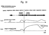
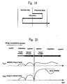
- a starter of internal combustion engine comprises a starter motor linked to the crankshaft of the internal combustion engine, a commutation position detection means adapted to output a pulse signal representing the detected commutation position of said starter motor and a control means adapted to control said starter motor so as to make said internal combustion engine get through the compression stroke by causing the piston of said internal combustion engine to turn backward to the explosion stroke and compress the gas in the combustion chamber in order to accumulate energy for forward revolution due to the reaction of the compression and then accumulate inertial energy in the rotary system surrounding said crankshaft by the effect of combining said energy and the rotational energy due to said starter motor, said control means being also adapted to detect the sense of rotation of said crankshaft on the basis of the change in the pulse intervals of the pulse signal output from said commutation position detecting means when making said starter motor turn backward.
- said control means may judge that the piston gets to the explosion stroke when the pulse intervals of the pulse signal output from said commutation position detecting means exceeds a predetermined value.
- a starter of an internal combustion engine comprises a starter motor linked to the crankshaft of the internal combustion engine, a crank angle sensor for detecting the angle of said crankshaft and a control means adapted to control said starter motor so as to make said internal combustion engine get through the compression stroke by causing the piston of said internal combustion engine to turn backward to the explosion stroke and compress the gas in the combustion chamber in order to accumulate energy for forward revolution due to the reaction of the compression and then accumulate inertial energy in the rotary system surrounding said crankshaft by the effect of combining said energy and the rotational energy due to said starter motor, said control means being also adapted to detect if said piston gets to the explosion stroke or not on the basis of the crank angle detected by said crank angle sensor when making said starter motor turn backward.
- said control means may determine the start of energization for turning said crankshaft forward on the basis of the crank angle detected by said crank angle sensor.
- a starter of an internal combustion engine comprises a starter motor linked to the crankshaft of the internal combustion engine, a camshaft sensor for detecting the cam position of said internal combustion engine and a control means adapted to control said starter motor so as to make said internal combustion engine get through the compression stroke by causing the piston of said internal combustion engine to turn backward to the explosion stroke and compress the gas in the combustion chamber in order to accumulate energy for forward revolution due to the reaction of the compression and then accumulate inertial energy in the rotary system surrounding said crankshaft by the effect of combining said energy and the rotational energy due to said starter motor, said control means being also adapted to detect if said piston gets to the explosion stroke or not on the basis of the signal from said camshaft sensor when making said starter motor turn backward.
- said control means may determine the start of energization for turning said crankshaft forward on the basis of the crank angle detected by said camshaft sensor.
- said control means may energize said starter motor for forward revolution after allowing said crankshaft to turn by inertia for a predetermined period of time after the termination of the energization of said starter motor for backward revolution . Further, said control means may start energizing said starter motor when it detects that the sense of revolution of said crankshaft is switched to forward revolution by the reaction force of the compression in the explosion stroke. Furthermore, said starter motor may be made to turn the piston forward to the compression stroke before it is turned backward to the explosion stroke.
- the piston of the engine is made to turn backward from the halted position to the explosion stroke by the starter motor in order to compress the gas in the combustion chamber and store the energy for forward revolution due to the reaction of the compression so that the crankshaft may be driven to turn forwardly by the above energy to which the rotational energy of the starter motor is added.
- the internal combustion engine can be started with a starter motor that shows a small torque and hence consumes little power.
- the crankshaft is made to turn forward midway of the compression stroke before it is made to turn backward in order to compress the gas in the combustion chamber and stores the energy for backward revolution due to the reaction of the compression, subsequently the inertial energy is stored in the rotary system by using the above energy when driving the crankshaft to turn backward to the explosion stroke so that energy for forward revolution can be sufficiently stored by the compressed gas in the combustion chamber produced as a result of the subsequent backward revolution in the next explosion stroke.
- the inertial energy will be large enough for driving the crankshaft to turn forward and get through the compression stroke.
- the internal combustion engine can be reliably started if no long stroke exists between the explosion stroke and the compression stroke as in the case of a 2-cycle engine.
- a starter of an internal combustion engine is characterized in that the internal combustion engine is designed to get through the compression stroke by the effect of combining the inertial energy of rotation of the crankshaft and the rotational energy of the starter motor when the internal combustion engine is made to start moving, said starter motor is linked to the crankshaft of said internal combustion engine and its performance is selectively used depending on its rotational speed.
- the starting torque of the starter motor can be raised to enhance the rising rate of rotational speed by means of changing a motor characteristics.
- the predetermined rotational speed is reached, the maximum rotational speed can be raised further and the inertial energy can be efficiently added to the rotary system.
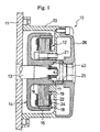
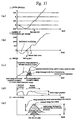
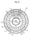
- FIG. 1 is a schematic cross sectional view of Embodiment 1 of engine starter motor according to the invention
- FIG. 2 is a schematic front view of the starter motor of FIG. 1 from which the housing and the cover are removed
- FIG. 3 is a schematic block diagram of the control system of the starter motor of FIG. 1.
- a starter motor 10 of FIG. 1 (hereinafter simply referred to as motor) is linked directly to a 4-cycle engine of motor bicycle and provided with a stator 12 rigidly secured to an engine case 11 of the engine and a rotor 14 linked to a crankshaft 13 of the engine.
- the rotor 14 is provided with a yoke 15 made of a magnetic material such as iron and having a shape of a bottomed short cylinder.
- a boss section 16 having a cylindrical profile is integrally formed on and concentrically projecting from the inner surface the bottom wall of the yoke 15.
- the boss section 16 and the crankshaft 13 are coupled together by means of a set nut 17 at the respective tapered surfaces thereof to give rise to a wedge effect, the rotor 14 is rigidly secured to the crankshaft 13 so as to integrally revolve with the latter.
- a plurality of permanent magnets 18 for producing field poles are arranged peripherally on the inner peripheral surface of the yoke 15 in such a way that any two adjacently located ones shows opposite polarities.
- the stator 12 of the motor 10 comprises a core 19 made of a magnetic material such as iron and having a shape of a low profile disk that rather resembles a star.
- the core 19 is rigidly secured by means of a bolt 21 to a housing 20 arranged on the outer surface of the engine case 11 concentrically with the crankshaft 13.
- a cover 26 is arranged to the outside of the housing 20.
- the rotor 14 is arranged within the housing 20 to surround the stator 12 and it is adapted to move around the stator 12 as it is driven by the crankshaft 13.
- the core 19 is formed by laying a number of thin plates of a magnetic material such as iron one on the other to form an integral entity and has a doughnut-shaped main body 22.
- a plurality of salient poles 23 are radially projecting from the outer periphery of the core main body 22.
- Each of the salient poles 23 is wound by a stator coil 24 for three-phase winding, which the coil 24 is connected to a motor driver 31 via a terminal (not shown) by means of a lead wire and a wire harness (not shown).
- the motor 10 is a brushless motor driven by the motor driver 31.
- the motor 10 is also provided with a plurality of (e.g., three) commutation position sensors 25 that are arranged in the housing 20 and adapted to sense the magnetism of the permanent magnets 18 and detect the rotary position of the rotor 14.
- the output of the commutation position sensors 25 is fed to the motor driver 31 by way of a CPU 32 so that the motor driver 31 generates an energization signal corresponding to the detection signal from the commutation position sensors 25 and feeds the stator coils 24 with an electric current on the basis of the signal in order to sequentially and magnetically energize the stator coils 24.
- a rotating magnetic field is formed by the stator coils 24.
- the rotating magnetic field acts on the permanent magnets 18 and the rotor 14 is driven to rotate by the rotating magnetic field.
- the turning effort of the rotor 14 is transmitted to the crankshaft 13 by way of the boss section 16 of the yoke 15 to cause the engine to start moving.
- the motor 10 is driven by the motor driver 31 under the control of the CPU (control means) 32.
- the CPU 32 is connected to a camshaft sensor 33 for detecting the movement of a valve cam, a starter switch 34 and an ignition switch 39 of the engine.
- the CPU 32 is also connected to an ignition coil 35 for igniting the fuel in the engine by way of an ignition unit 36.
- It is further connected to a ROM 37 storing the motor driver drive logic and various control programs including the engine control program and a RAM 38 storing the data from various sensors.
- it sends control signals to various components of the system including the motor driver 31 and the ignition unit 36 on the basis of the detected values of the various sensors to control the motor 10 and also the operation of igniting the fuel in the engine.
- the motor 10 itself and the CPU 32 are powered by a power source that is a battery (not shown) loaded in the vehicle.
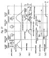
- FIG. 4 is a chart illustrating the starting motion of a 4-stroke engine that can be triggered by the starter motor of FIG. 1, where (a) shows the load of revolution in each of the strokes and (b) show the starting energy of the engine, while (c) shows the position of the piston at the start and (d) shows the signal of the camshaft sensor.
- the load for driving the crankshaft 13 to revolve varies as a function of the strokes of the operation of the engine. More specifically, the load required for driving the crankshaft 13 is relatively small in the exhaust stroke and the intake stroke because the piston moves up and down while a valve is kept open in those strokes. On the other hand, the load required for driving the crankshaft 13 is large in the compression stroke and maximized at a position slightly before the top dead center because the piston has to move up and down while the valve is kept closed in that stroke. Therefore, the piston of the engine normally stops at a position before entering the compression stroke and any conventional starter motor is designed to cause the engine to start moving from that piston position. Thus, the known motor is required to supply the crankshaft with energy in a manner as indicated by a broken line in FIG. 4 in order to cause the engine to overcome the load in the compression stroke when the engine starts moving.
- the piston located before the compression stroke is temporarily moved back to the exhaust stroke by reversely turning the motor 10 prior to causing the engine to start moving.
- the engine enters the compression stroke after making a short approach with a small load of revolution and overcome the largest load by the combined effect of the inertial energy of the rotary system including the flywheel of the engine and the drive torque of the motor to consequently reduce the load of the motor so that the motor may be down-sized and operate at a low power consumption rate.
- the CPU 32 firstly recognizes the current position of the piston on the basis of the detection signal of the camshaft sensor 33 and determines if it is necessary to return the piston to the exhaust stroke or not. In other words, the CPU 32 recognizes the current position of the piston by means of the signal from the camshaft sensor 33 so as to reliably cause the piston to move into the exhaust stroke.
- the CPU 32 determines to cause the piston to move back to the exhaust stroke and issues a command to the motor driver 31 to make the motor 10 turn backward temporarily so as to cause the crankshaft 13 to rotate into the exhaust stroke. For example, if the piston is found at position P as shown in (c) of FIG. 4 when the ignition switch is turned ON, it is temporarily moved back to the exhaust stroke as indicated by the arrow.
- the position of the piston is constantly monitored by the camshaft sensor 33 so that the latter issues an H signal when the piston gets to the exhaust stroke. As the detection signal (H) is issued from the camshaft sensor 33 to tell that the piston is in the exhaust stroke, the CPU 32 causes the motor 10 to cease the reverse turn and temporarily halt at position Q.
- the piston is returned to position Q in the exhaust stroke that is found within the "range for starting forward turn” in (c) of FIG. 4, it is desirable that the piston is moved back to a position near the bottom dead center before the start of the exhaust stroke that allows the piston to have the longest approach run.
- the position Q "in the exhaust stroke" where the piston starts turning forward may include a position near the bottom dead center in the explosion stroke and a position near the top dead center in the intake stroke before or after the exhaust stroke.
- the CPU 32 determines that it is not necessary to return the piston to the exhaust stroke and hence does not cause it to turn backward in a manner as described above.
- the motor 10 is made to revolve backward when the ignition switch 39 is turned ON in order for the motor 10 to start revolving forward immediately to eliminate any time lag before the start of the engine when the starter switch 34 is turned ON. Therefore, the motor 10 does not necessarily have to revolve backward when the ignition switch is turned ON. Alternatively, it may be so arranged that the motor 10 starts revolving backward when the starter switch 34 is turned ON. Still alternatively, it may be so arranged that the motor 10 revolves backward when the engine is stopped.
- the starter switch 34 inputs an engine start signal
- the CPU 32 outputs a signal for causing the motor driver 31 to make the motor 10 revolve forward so that the engine may start moving from the exhaust stroke. Since the crankshaft 13 turns with a small load in the exhaust stroke and the intake stroke, the motor 10 will substantially gets to the largest number of revolutions per unit time that can taken place when it revolves without load before it gets into the compression stroke. In other words, the motor 10 will be in an almost saturated state. Therefore, the crankshaft 13 is also driven by the motor 10 to turn at the largest number of revolutions immediately before the compression stroke and the inertial energy stored in the inertial mass of the rotary system is maximized when the engine enters the compression stroke.
- crankshaft 13 is driven to rotate by the combined effect (thick solid line) of the inertial energy of the engine (dotted broken line) and the rotational energy of the starter motor (solid line) in the compression stroke as shown in (b) of FIG. 4.
- the drive torque of the motor is made Tm ⁇ T/2 when Tm ⁇ Ti as seen from (b) in FIG. 4.
- the embodiment is designed to get over the load of the compression stroke mainly by means of the inertial energy subordinately by the motor energy and the engine can be made to start moving by means of a motor 10 whose largest torque (lock torque) is less than 1/2 of the ride over torque T necessary for getting over the load of the compression stroke.
- the motor 10 is designed to divide its drive energy into two parts and delivers them to the crankshaft 13 respectively during the approach run and during the time of riding over. Therefore, a motor with a relatively low output level according to the invention can be used to generate a large ride over torque if compared with conventional motors that are required to get over a large load in the compression stroke with a single delivery of energy.
- the backward turn sequence down to the exhaust stroke of the attempt of restarting the engine immediately thereafter is automatically followed if the halt of the engine is detected while the ignition switch 39 is held ON. Therefore, when the starter switch 34 is tuned ON for another time, the motor 10 immediately starts revolving forward without giving rise to any time lag. Additionally, the motor 10 is allowed to operate only when the brake is being operated and/or when the gear is found in the neutral position so that any unintended burst of the vehicle is inhibited.
- FIG. 5 is a chart illustrating the starting motion of a 2-stroke engine that can be triggered by the embodiment.
- the strokes of intake, compression, explosion and exhaust proceeds within a single turn of the crankshaft of the 2-stroke engine.
- the 2-stroke engine is not provided with an intake valve and an exhaust value unlike the 4-stroke engine, the piston of the engine itself takes the part of the valves.
- the intake port and the exhaust port of the cylinder of the 2-stroke engine are blocked by the piston both in the compression stroke and in the explosion stroke. Additionally, the exhaust stroke and the intake stroke take place simultaneously. In other words, both the exhaust port and the intake port are open when the piston is located near the bottom dead center.
- the exhaust stroke of the 4-stroke engine corresponds to the period between the time when at least either the exhaust port or the intake port is opened and the time when the piston gets to the bottom dead center of the 2-stroke engine as the engine is operated (to turn forward).
- the piston of the engine provided with a motor 10 according to the invention is temporarily returned to the exhaust stroke before it is made to start moving in order to utilize the inertial energy of the crankshaft 13 so that the initial compression stroke can be got through with a torque smaller than that of any conventional motor of the type under consideration. Then, the motor can be downsized to reduce the manufacturing cost and the power consumption rate of the motor. Still additionally, if a starter according to the invention uses a magnet for the magnetic field system of the motor, the magnet is not required to show excessive magnetic force so that it is possible reduce the rotational resistance of the motor and hence the specific fuel consumption of the engine without sacrificing the output power of the engine.
- Embodiment 2 of starter motor of engine according to the invention will be described. However, since the configuration of this embodiment is basically identical with that of Embodiment 1, the parts that are common to those embodiments will not be described any further.
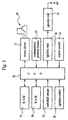
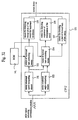
- FIG. 6 is a schematic block diagram of the control system of Embodiment 2 of starter motor according to the invention.
- the motor 10 is driven by motor driver 31 under the control of CPU (control means) 32.
- the CPU 32 is connected to various sensors including a motor temperature sensor 42, a commutation position sensor 25 and a battery voltage sensor 43 and various switches including an engine starter switch 34 and an ignition switch 39.
- the CPU 32 is also connected to an ignition coil 35 for igniting the fuel in the engine by way of an ignition unit 36.
- It is further connected to a ROM (storage means) 37 storing the motor driver drive logic and various control programs including the engine control program and a RAM 38 storing the data from various sensors.
- the motor driver 31 and the ignition unit 36 sends control signals to various components of the system including the motor driver 31 and the ignition unit 36 on the basis of the detected values of the various sensors to control the motor 10 and also the operation of igniting the fuel in the engine.
- the motor 10 itself and the CPU 32 are powered by a power source that is a battery (not shown) loaded in the vehicle.
- FIG. 7 is a chart illustrating the starting motion of a 4-stroke engine that can be triggered by the starter motor 10 of FIG. 6, where (a) shows the load of start in each of the strokes, (b) shows the starting energy produced by the drive force of the motor 10 and the inertia of the crankshaft 13, (c) shows the pulse signal from the commutation position sensor 25 and (d) shows the signal of the camshaft sensor.
- the load for driving the crankshaft 13 to revolve varies as a function of the strokes of the operation of the engine. More specifically, the load required for driving the crankshaft 13 is relatively small in the exhaust stroke and the intake stroke because the piston moves up and down while a valve is kept open in those strokes. On the other hand, the load required for driving the crankshaft 13 is large in the compression stroke and maximized at a position slightly before the top dead center because the piston has to move up and down while the valve is kept closed in that stroke. Therefore, the piston of the engine normally stops at a position before entering the compression stroke and any conventional starter motor is designed to cause the engine to start moving from that piston position. Thus, the known motor is required to supply the crankshaft with energy in a manner as indicated by a broken line in FIG. 7 in order to cause the engine to overcome the load in the compression stroke when the engine starts moving.
- the engine enters the compression stroke after making a short approach with a small load of revolution and overcome the largest load by the combined effect of the inertial energy of the rotary system including the flywheel of the engine and the drive torque of the motor to consequently reduce the load of the motor so that the motor may be down-sized and operate at a low power consumption rate.
- the CPU 32 issues a command to the motor driver 31 to energize and make it turn backward for a predetermined period of time in order to cause the crankshaft 13 to turn backward to the exhaust stroke. Additionally, after the energization for backward revolution, the energization of the motor 10 is suspended for a predetermined period of time to cause the crankshaft 13 to rotate simply by inertia. After the suspension of energization for the predetermined period of time, the motor 10 is energized to turn forward and cause the crankshaft 13 to revolve forward, thereby making the engine start moving.
- the motor 10 is 10 made to turn backward when the starter switch 34 is turned ON in the above description, it may alternatively be so arranged that the motor 10 is made to turn backward when the ignition switch 39 is turned ON so that the motor 10 may be able to turn forward once the starter switch 34 is turned ON and, therefore, the engine may be made to start moving without any time lag. Therefore, the motor 10 does not necessarily have to revolve backward when the starter switch 34 is turned ON. Alternatively, it may be so arranged that the motor 10 starts revolving backward when the ignition switch 39 is turned ON. Still alternatively, it may be so arranged that the motor 10 revolves backward when the engine is stopped.
- the above starting motion generally follows one of the three patterns of motion as described below depending on the position at which the position is halted. They include the one that appears when the piston is located at the ordinary halt position before the compression stroke (pattern 1 ⁇ ), the one that appears when the piston is located immediately before or after the top dead center between the exhaust stroke and the intake stroke (pattern 2 ⁇ ) and the one that appears when the piston is located near the bottom dead center before the exhaust stroke (pattern 3 ⁇ ).
- the starter switch 34 issues a command to make the motor 10 turn backward for t 1 seconds and the piston move from position A to position B. Thereafter, the energization of the motor 10 is suspended for t 2 seconds.
- the crankshaft 13 keeps on turning backward due to the inertial force obtained by the energization for t 1 seconds. Since the piston does not compress any gas from the intake stroke to the exhaust stroke and hence the load torque is small, the crankshaft 13 can easily keep on revolving by inertia. However, the inertial energy is consumed by the load torque to gradually reduce the rotational speed until the piston stops at position C.
- the duration t 1 of energization for backward revolution is made longer than the time by which the piston can return to a position near the bottom dead center before the exhaust stroke due to the inertial force obtained by the energization. If the duration t 1 is too long, the rotational speed of the crankshaft 13 can become too high and generate too large inertial energy so that the explosion stroke can be got through during the time t 2 . Thus, the duration t 1 has to be so selected that the explosion stroke would not be got through while the crankshaft 13 is turning by inertia if the crankshaft 13 is driven to turn backward when the position is located at the bottom dead center before the compression stroke. Thus, the lower and higher limits of the duration t 1 of energization have to be defined so as to satisfy the above requirements.
- the motor 10 After the time t 2 , the motor 10 is energized to turn forward. However, there may be occasions where the piston cannot get back to the exhaust stroke while it is turning by inertia if the time t 2 of suspension of energization is too short. Thus, the lower limit of the time t 2 is defined by taking this situation into consideration. The piston will successfully move from position B to position C in the exhaust stroke during the time t 2 if the above limits for the time t 2 and the duration t 1 are observed.
- the piston is returned to position C in the exhaust stroke that is found within the "range for starting forward turn” in (d) of FIG. 7, it is desirable that the piston is moved back to a position near the bottom dead center before the start of the exhaust stroke that allows the piston to have the longest approach run.
- the position C "in the exhaust stroke" where the piston starts turning forward may include a position near the bottom dead center in the explosion stroke and a position near the top dead center in the intake stroke before or after the exhaust stroke.
- the CPU 32 When the time t 2 is over, the CPU 32 outputs a signal for causing the motor driver 31 to make the motor 10 revolve forward so that the engine may start moving from the exhaust stroke. Since the crankshaft 13 turns with a small load in the exhaust stroke and the intake stroke, the motor 10 will substantially gets to the largest number of revolutions per unit time that can taken place when it revolves without load before it gets into the compression stroke. In other words, the motor 10 will be in an almost saturated state. Therefore, the crankshaft 13 is also driven by the motor 10 to turn at the largest number of revolutions immediately before the compression stroke and the inertial energy stored in the inertial mass of the rotary system is maximized when the engine enters the compression stroke.
- crankshaft 13 is driven to rotate by the combined effect (thick solid line) of the inertial energy of the engine (dotted broken line) and the rotational energy of the starter motor (solid line) in the compression stroke as shown in (b) of FIG. 7.
- the drive torque of the motor is made Tm ⁇ T/2 when Tm ⁇ Ti as seen from (b) in FIG. 7.
- the embodiment is designed to get over the load of the compression stroke mainly by means of the inertial energy subordinately by the motor energy and the engine can be made to start moving by means of a motor 10 whose largest torque (lock torque) is less than 1/2 of the ride over torque T necessary for getting over the load of the compression stroke.
- the motor 10 is designed to divide its drive energy into two parts and delivers them to the crankshaft 13 respectively during the approach run and during the time of riding over. Therefore, a motor with a relatively low output level according to the invention can be used to generate a large ride over torque if compared with conventional motors that are required to get over a large load in the compression stroke with a single delivery of energy.
- the piston is located near the top dead center between the exhaust stroke and the intake stroke (position D) and then driven to turn backward from there to position E as the motor is energized for the time t 1 . Thereafter, the piston returns to the bottom dead center of the exhaust stroke by inertia and then enters the explosion stroke.
- the torque of the load of revolution increases due to the load of compression generated by the piston in the explosion stroke and the inertial energy is consumed quickly by the torque of the load to make the rotational speed falls and eventually cause the piston to completely halt (position F).
- the crankshaft 13 may be driven to turn forward slightly by the reaction force of compression produced by the piston but eventually stops at position G near the bottom dead center.
- the piston is located near the bottom dead center before the exhaust stroke (position H) and then driven to turn backward. Since it enters the explosion stroke immediately after the start of the backward revolution, the torque of the load of revolution is generated by the piston due to the load of compression of the latter also immediately after the start of the backward revolution. Therefore, the number of revolutions per unit time of the crankshaft 13 is not raised remarkably nor any substantial inertial energy is generated.
- Embodiment 2 of motor 10 according to the invention is made to turn backward for the time t 1 set under the conditions described above by referring to the pattern 1 ⁇ before the engine is made to start moving. Then, the crankshaft 13 is made to turn by inertia, while the power supply is suspended for the time t 2 set under the conditions as discussed above by referring to the patterns 1 ⁇ and 3 ⁇ . Thereafter, the motor 10 is made to turn forward to temporarily bring the piston back to the exhaust stroke in order to make it possible to cause the engine to start moving. As discussed above, the motor 10 can reliably bring the piston back to the exhaust stroke by selecting appropriate values for the times t 1 and t 2 respectively. Thus, the engine can be reliably made to start moving from the exhaust stroke without providing a sensor for detecting the position of the piston such as a camshaft sensor so that the cost of the engine can be reduced for the reason of the absence of such sensors.
- the load of the motor 10 can be reduced and hence the motor 10 can be downsized to make it energy-saving. Still additionally, if a starter according to the invention uses a magnet for the magnetic field system of the motor, the magnet is not required to show excessive magnetic force so that it is possible reduce the rotational resistance of the motor and hence the specific fuel consumption of the engine without sacrificing the output power of the engine.
- the backward turn sequence down to the exhaust stroke of the attempt of restarting the engine immediately thereafter is followed immediately if the halt of the engine is detected while the ignition switch is held ON or automatically if the halt of the engine is detected when the starter switch 34 is released. Therefore, when the starter switch 34 is turned ON for another time, the motor 10 immediately starts revolving forward without giving rise to any time lag as described earlier. Additionally, the motor 10 is allowed to operate only when the brake is being operated and/or when the gear is found in the neutral position so that any unintended burst of the vehicle is inhibited.
- the extent (angle) of reverse turn can vary enormously as a function of the change in the performance of the motor due to fluctuations of the battery voltage and/or those of the temperature and/or the change in the torque of the load of revolution (friction) of the engine caused by the change in the oil viscosity also due to fluctuations of the temperature if appropriate values are selected respectively for the time t 1 and the time t 2 .
- the ROM 37 of this embodiment of motor 10 is made to store a map 1 for the time t 1 that carries values for the time t 1 obtained by using the temperature of the starter motor and the supply voltage as parameters and another map 2 for the time t 2 that carries values for the time t 2 also obtained by using the temperature of the starter motor and the supply voltage as parameters so that appropriate values may be selected for t 1 and t 2 by referring to the respective maps.
- FIGS. 8 and 9 show examples of the maps 1 and 2.
- the output power of the motor 10 falls as the voltage of the battery falls so that the time required to store the rotational energy necessary for returning the piston to the right position increases.
- the oil viscosity rises as the temperature falls so that the time required to store the rotational energy necessary for moving the piston increases.
- inertial energy will be consumed at a high rate when the piston is made to turn by inertia so that a large volume of inertial energy has to be stored.
- appropriate values are selected for the time t 1 by taking the temperature of the starter motor and the battery voltage into consideration, and it shows the relationship between the time t 1 and these factors as a map.
- the map 2 may be made to additionally contain data on the battery voltage so that the crankshaft 13 can reliably returns to the predetermined position by prolonging the time t 2 which is the time during which the crankshaft 13 turns by inertia in order to compensate the loss of inertial energy stored in the energization process for backward revolution caused by a fall of the battery.
- the CPU 32 obtains the motor temperature Ts from the motor temperature sensor 42 and the battery voltage V from the battery voltage sensor 43 and determines both the times t 1 and t 2 on the basis of these values by referring to the map 1 for the time t 1 and the map 2 for the time t 2 .
- both the times t 1 and t 2 are compensated in terms of temperature and fluctuations of the voltage so that the piston can reliably be made to return to the exhaust stroke regardless of any changes in the environmental factors.
- the CPU 32 comprises a means for computationally determining the time t 1 from the motor temperature Ts and the battery voltage V, and a means for computationally determining the time t 2 from the temperature so that it can computationally determine those values. Then, the approximate expressions as shown below can be used for determining the time t 1 and time t 2 from the motor temperature and the battery voltage.
- the temperature that can be used as parameter is not limited to that of the motor and that of the engine cooling water, that of the engine oil or that of the ambient air may alternatively be used. Still alternatively, any of the above temperatures may be used as parameters in addition to the temperature of the motor 10 when preparing a map and an approximate expression.
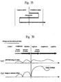
- FIG. 10 is a chart illustrating the starting motion of a 2-stroke engine that can be triggered by the embodiment.
- the strokes of intake, compression, explosion and exhaust proceeds within a single turn of the crankshaft of the 2- stroke engine.
- the 2- stroke engine is not provided with an intake valve and an exhaust value unlike the 4-stroke engine, the piston of the engine itself takes the part of the valves.
- the intake port and the exhaust port of the cylinder of the 2-stroke engine are blocked by the piston both in the compression stroke and in the explosion stroke. Additionally, the exhaust stroke and the intake stroke take place simultaneously. In other words, both the exhaust port and the intake port are open when the piston is located near the bottom dead center.
- the exhaust stroke of the 4-stroke engine corresponds to the period between the time when at least either the exhaust port or the intake port is opened and the time when the piston gets to the bottom dead center of the 2-stroke engine as the engine is operated (to turn forward).
- Embodiment 3 of starter motor of engine according to the invention will be described. However, since the configuration of this embodiment is basically identical with that of Embodiment 1, the parts that are common to those embodiments will not be described any further.
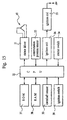
- FIG. 11 is a schematic block diagram of the control system of Embodiment 2 of starter motor according to the invention.
- the motor 10 is driven by motor driver 31 under the control of CPU 32.
- the CPU 32 is connected to various sensors including a commutation position sensor 25 and various switches including an engine starter switch 34 and an ignition switch 39.
- the CPU 32 is also connected to an ignition coil 35 for igniting the fuel in the engine by way of an ignition unit 36.
- It is further connected to a ROM (storage means) 37 storing the motor driver drive logic and various control programs including the engine control program and a RAM 38 storing the data from various sensors.
- ROM storage means
- the motor driver 31 and the ignition unit 36 sends control signals to various components of the system including the motor driver 31 and the ignition unit 36 on the basis of the detected values of the various sensors to control the motor 10 and also the operation of igniting the fuel in the engine.
- the motor 10 itself and the CPU 32 are powered by a power source that is a battery (not shown) loaded in the vehicle.
- FIG. 12 is a schematic diagram of the functional blocks of the CPU 32.
- a pulse signal indicating the commutation position is input to the CPU 32 from the commutation position sensor 25 and the CPU 32 has a motor rotational speed computing means 51 for computationally determining the rotational speed of the motor 10 on the basis of the pulse signal and a motor rotational angle computing means 52 for computationally determining the rotational angle of the motor 10 also on the basis of the pulse signal.
- the CPU 32 has a means 55 for directing energization of the motor for backward revolution to the motor driver 31 and a means 56 for directing suspension of energization of the motor respectively on the basis of the time t 1 and the time t 2 selected by the means 53 and 54. Finally, the CPU 32 also has a means 57 for directing a start of forward turn of the motor to cause the engine to start moving after the time t 2 .
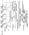
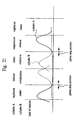
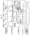
- FIG. 13 is a chart illustrating the starting motion of an engine that can be triggered by starter motor, where (a) shows the load of revolution in each of the strokes, (b) shows the starting energy of the engine produced by the drive force of the motor 10 and the inertia of the crankshaft 13, (c) shows the pulse signal from the commutation position sensor 25 and (d) shows the position of the piston when the engine starts moving.
- the load for driving the crankshaft 13 to revolve varies as a function of the strokes of the operation of the engine. More specifically, the load required for driving the crankshaft 13 is relatively small in the exhaust stroke and the intake stroke because the piston moves up and down while a valve is kept open in those strokes. On the other hand, the load required for driving the crankshaft 13 is large in the compression stroke and maximized at a position slightly before the top dead center because the piston has to move up and down while the valve is kept closed in that stroke. Therefore, the piston of the engine normally stops at a position before entering the compression stroke and any conventional starter motor is designed to cause the engine to start moving from that piston position. Thus, the known motor is required to supply the crankshaft with energy in a manner as indicated by a broken line in FIG. 13 in order to cause the engine to overcome the load in the compression stroke when the engine starts moving.
- the engine enters the compression stroke after making a short approach with a small load of revolution and overcome the largest load by the combined effect of the inertial energy of the rotary system including the flywheel of the engine and the drive torque of the motor to consequently reduce the load of the motor so that the motor may be down-sized and operate at a low power consumption rate.
- the CPU 32 issues a command to the motor driver 31 to energize and make it turn backward for the predetermined period of time t 1 in order to cause the crankshaft 13 to turn backward to the exhaust stroke. Additionally, after the energization for backward revolution, the energization of the motor 10 is suspended for the predetermined period of time t 2 to cause the crankshaft 13 to rotate simply by inertia. After the suspension of energization for the predetermined period of time, the motor 10 is energized to turn forward and cause the crankshaft 13 to revolve forward, thereby making the engine start moving.
- the motor 10 is 10 made to turn backward when the starter switch 34 is turned ON in the above description, it may alternatively be so arranged that the motor 10 is made to turn backward when the ignition switch 39 is turned ON so that the motor 10 may be able to turn forward once the starter switch 34 is turned ON and, therefore, the engine may be made to start moving without any time lag. Therefore, the motor 10 does not necessarily have to revolve backward when the starter switch 34 is turned ON. Alternatively, it may be so arranged that the motor 10 starts revolving backward when the ignition switch 39 is turned ON. Still alternatively, it may be so arranged that the motor 10 revolves backward when the engine is stopped or the starter switch 34 is released (OFF).
- the above starting motion generally follows one of the three patterns of motion as described below depending on the position at which the position is halted. They include the one that appears when the piston is located at the ordinary halt position before the compression stroke (pattern 1 ⁇ ), the one that appears when the piston is located immediately before or after the top dead center between the exhaust stroke and the intake stroke (pattern 2 ⁇ ) and the one that appears when the piston is located near the bottom dead center before the exhaust stroke (pattern 3 ⁇ ).
- the starting motion that follows the pattern 1 ⁇ will be discussed.
- the starter switch 34 is turned ON, the motor 10 turn backward for t 1 seconds by means of a command issued from the means 55 for directing energization of the motor for backward revolution of the CPU 32 and the piston move from position A to position B.
- the energization of the motor 10 is suspended for t 2 seconds by a command issued from the means 56 for directing suspension of energization of the motor.
- the crankshaft 13 keeps on turning backward due to the inertial force obtained by the energization for t 1 seconds.
- the crankshaft 13 can easily keep on revolving by inertia. However, the inertial energy is consumed by the load torque to gradually reduce the rotational speed until the piston stops at position C.
- the CPU 32 constantly monitors the rotational speed and the rotational angle of the motor 10 by way of the motor rotational speed computing means 51 and the motor rotational angle computing means 52, using the pulse signal indicating the commutation position from the commutation position sensor 25. More specifically, it computationally determines the rotational speed of the motor on the basis of the number of pulses and the pulse intervals of the pulse signal indicating the commutation position as counted in during the time of energization and also the rotational angle on the basis of the accumulated number of the pulses. It also computationally determines the rate of change of the rotational speed (dv/dt) of the motor 10 on the basis of the pulse signal indicating the commutation position.
- the ROM 37 stores the reference value Xr for the rate of change of the rotational speed and the target rotational speed Nr of the motor 10 to be achieved during the time t 1 .
- the extent of backward turn correcting means 53 recognizes the friction of the engine on the basis of the increasing rotational speed and feeds it back for controlling the rotational motion of the motor 10.
- the extent of backward turn correcting means 53 compares the rate of change of the rotational speed as determined by observing the rotational motion of the motor 10 with the above reference value Xr. If the rate of change of the rotational speed is lower than the reference value and hence the rate of change of the rotational speed is low, the time required for the motor 10 to get to the target rotational speed will be longer than the estimated time, the means 53 judges that the load of rotation of the crankshaft 13 is greater than the expected value. If the operation is left uncorrected, the friction of the engine will be greater than the estimated value during the time of rotation by inertia so that the piston may not be able to return to the expected position. Therefore, the means 53 raises the target rotational speed Nr to increase the inertial energy to be stored in the crankshaft 13 so that the piston may be able to return to the exhaust stroke as expected.
- the means 53 judges that the load of rotation of the crankshaft 13 is smaller than the expected value. If the operation is left uncorrected, the friction of the engine will be smaller than the estimated value during the time of rotation by inertia so that the piston may pass by the expected position. Therefore, the means 53 lowers the target rotational speed Nr to decrease the inertial energy to be stored in the crankshaft 13 so that the piston may be able to return to the exhaust stroke as expected.
- the extent of backward turn correcting means 53 also monitors the rotational speed of the motor itself to recognize the inertial energy of rotation. More specifically, when the rotational speed gets to the target value Nr, it judges that inertial energy is stored by the predetermined amount if the current time is before the end of the time t 1 . Then, it carries out a correcting operation of reducing the time t 1 and causes the means 55 for directing energization of the motor for backward revolution to suspend the energization of the motor 10. When, on the other hand, the rotational speed does not get to the target value Nr, the means 53 judges that inertial energy is not sufficiently stored if the current time is at the end of the time t 1 . Then, it carries out a correcting operation of extending the time t 1 and causes the means 55 to continue the energization of the motor 10.
- the ROM 37 also stores the reference angle ⁇ r for backward revolution of the motor 10 and, during the rotation by inertia, the extent of inertial turn correcting means 54 compares the angle of backward revolution as a function of the time of energization for backward revolution and the reference angle ⁇ r.
- an angle of 180° is selected for the reference angle ⁇ r because the piston will probably be in the exhaust stroke with that angle if the backward revolution is started from the bottom dead center that is the possible remotest position before entering the compression stroke. Therefore, the means 54 of the CPU 32 judges if the rotational angle of the motor 10 has exceeded 180° or not and hence if the input pulse signal of the commutation position is good for 180° or not.
- the means 54 If it is determined by the means 54 that the rotational angle exceeds 180°, it judges that the piston has returned to the exhaust stroke and hence the objective of the suspension of energization is achieved so that it determines to terminate the energization if the current time is before the end of the time t 2 . Then, it notifies the means 56 for directing suspension of energization of the motor that the energization is terminated and issues a command to the means 57 for directing a start of forward turn of the motor to make the latter start driving the motor 10 to rotate immediately once the starter switch 34 is turned ON.
- the means 56 notifies the means 56 that the time of suspension of energization is temporarily stopped and, at the same time, orders the means 55 to energize the motor so as to make it turn backward for a short period of time. After the short period of energizing the motor for backward revolution, the time t 2 is started once again and terminate it when the total rotational angle exceeds 180°.
- the piston is returned to position C in the exhaust stroke that is found within the " range for starting forward turn” in (c) of FIG. 13, it is desirable that the piston is moved back to a position near the bottom dead center before the start of the exhaust stroke that allows the piston to have the longest approach run.
- the position C "in the exhaust stroke" where the piston starts turning forward may include a position near the bottom dead center in the explosion stroke and a position near the top dead center in the intake stroke before or after the exhaust stroke.
- the means 57 for directing a start of forward turn of the motor of the CPU 32 outputs a signal for causing the motor driver 31 to make the motor 10 revolve forward so that the engine may start moving from the exhaust stroke. Since the crankshaft 13 turns with a small load in the exhaust stroke and the intake stroke, the motor 10 will substantially gets to the largest number of revolutions per unit time that can taken place when it revolves without load before it gets into the compression stroke. In other words, the motor 10 will be in an almost saturated state. Therefore, the crankshaft 13 is also driven by the motor 10 to turn at the largest number of revolutions immediately before the compression stroke and the inertial energy stored in the inertial mass of the rotary system is maximized when the engine enters the compression stroke.
- crankshaft 13 is driven to rotate by the combined effect (thick solid line) of the inertial energy of the engine (dotted broken line) and the rotational energy of the starter motor (solid line) in the compression stroke as shown in (b) of FIG. 13.
- the drive torque of the motor is made Tm ⁇ T/2 when Tm ⁇ Ti as seen from (b) in FIG. 13.
- the embodiment is designed to get over the load of the compression stroke mainly by means of the inertial energy subordinately by the motor energy and the engine can be made to start moving by means of a motor 10 whose largest torque (lock torque) is less than 1/2 of the ride over torque T necessary for getting over the load of the compression stroke.
- the motor 10 is designed to divide its drive energy into two parts and delivers them to the crankshaft 13 respectively during the approach run and during the time of riding over. Therefore, a motor with a relatively low output level according to the invention can be used to generate a large ride over torque if compared with conventional motors that are required to get over a large load in the compression stroke with a single delivery of energy.
- the piston is located near the top dead center between the exhaust stroke and the intake stroke (position D) and then driven to turn backward from there to position E as the motor is energized for the time t 1 . Thereafter, the piston returns to the bottom dead center of the exhaust stroke by inertia and then enters the explosion stroke.
- the torque of the load of revolution increases due to the load of compression generated by the piston in the explosion stroke and the inertial energy is consumed quickly by the torque of the load to make the rotational speed falls and eventually cause the piston to completely halt (position F).
- the pulse signal of the motor 10 indicating the commutation position shows a period that rapidly increases to by turn rapidly increase the rate of change of the rotational speed (the rate of decreasing speed) of the motor 10 until the latter exceeds the upper limit value Xmax.
- the extent of inertial turn correcting means 54 judges that the piston passes by the bottom dead center before the exhaust stroke and enters the explosion stroke to start receiving the compression resistance of the engine. As a result, the piston enters a region where the extent of the approach run can be maximized and inertial energy can be maximally infused into the crankshaft 13. In other words, it is detected that the piston has got to the region suited to start turning forward.
- the means 54 terminates the time t 2 . It then notifies the means 56 of the fact and issues a command for making the motor 10 start turning forward immediately. While the crankshaft 13 may be returned forward slightly by the reaction force of the compression of the piston at this time, the piston halts at position G near the bottom dead center.
- the piston is located near the bottom dead center before the exhaust stroke (position H) and then driven to turn backward. Since it enters the explosion stroke immediately after the start of the backward revolution, the torque of the load of revolution is generated by the piston due to the load of compression of the latter also immediately after the start of the backward revolution. Therefore, the number of revolutions per unit time of the crankshaft 13 is not raised remarkably nor any substantial inertial energy is generated.
- the period of the pulse signal that is once reduced by energization as a result of the operation of the motor 10 increases to become longer than the predetermined value so that the rotational speed falls below the predetermined lower limit value Vmin.
- the extent of backward turn correcting means 53 judges that the piston passes by the bottom dead center of the explosion stroke and compression torque begins to be generated. In other words, it judges that the objective of the backward revolution is achieved and immediately terminates the time t 1 . It then notifies the means 55 of the fact and issues a command to the means 57 to make the latter start driving the motor 10 to rotate immediately once the starter switch 34 is turned ON.
- the energization for forward revolution has to be started before the commutation pulse of the motor 10 exceeds the extent corresponding to 180° at maximum even before the termination of the time t 2 . Then, in a manner as described above, the cranking motion starts from this position.
- the motor 10 is made to turn backward for the time t 1 before the engine starts moving and then it is deenergized for the time t 2 to allow the crankshaft 13 to turn by inertia. Thereafter, the motor 10 is made to turn forward.
- the motor 10 computationally determines the rotational speed, the rate of change of the rotational speed and the rotational angle of the motor on the basis of the pulse signal indicating the commutation position and estimates the piston position to feed back and control the times t 1 and t 2 .
- the engine can be reliably made to start moving from the exhaust stroke without providing a sensor for detecting the position of the piston such as a camshaft sensor so that the cost of the engine can be reduced for the reason of the absence of such sensors.
- the load of the motor 10 can be reduced and hence the motor 10 can be downsized to make it energy-saving. Still additionally, if a starter according to the invention uses a magnet for the magnetic field system of the motor, the magnet is not required to show excessive magnetic force so that it is possible reduce the rotational resistance of the motor and hence the specific fuel consumption of the engine without sacrificing the output power of the engine.
- the backward turn sequence down to the exhaust stroke of the attempt of restarting the engine immediately thereafter is followed immediately and automatically if the halt of the engine is detected while the ignition switch is held ON. Therefore, when the starter switch 34 is turned ON for another time, the motor 10 immediately starts revolving forward without giving rise to any time lag as described earlier. Additionally, the motor 10 is allowed to operate only when the brake is being operated and/or when the gear is found in the neutral position so that any unintended burst of the vehicle is inhibited.
- FIG. 14 is a chart illustrating the starting motion of a 2-stroke engine that can be triggered by the embodiment.
- the strokes of intake, compression, explosion and exhaust proceeds within a single turn of the crankshaft of the 2-stroke engine.
- the 2-stroke engine is not provided with an intake valve and an exhaust value unlike the 4-stroke engine, the piston of the engine itself takes the part of the valves.
- the intake port and the exhaust port of the cylinder of the 2-stroke engine are blocked by the piston both in the compression stroke and in the explosion stroke. Additionally, the exhaust stroke and the intake stroke take place simultaneously. In other words, both the exhaust port and the intake part are open when the piston is located near the bottom dead center.
- the exhaust stroke of the 4-stroke engine corresponds to the period between the time when at least either the exhaust port or the intake port is opened and the time when the piston gets to the bottom dead center of the 2-stroke engine as the engine is operated (to turn forward).
- Embodiment 4 of starter motor of engine according to the invention will be described. However, since the configuration of this embodiment is basically identical with that of Embodiment 1, the parts that are common to those embodiments will not be described any further.
- FIG. 15 is a schematic block diagram of the control system of Embodiment 2 of starter motor according to the invention.
- the motor 10 is driven by motor driver 31 under the control of CPU (control means) 32.
- the CPU 32 is connected to a camshaft sensor 33 for detecting the movement of a valve cam, an engine starter switch 34 and an ignition switch 39.
- the CPU 32 is also connected to an ignition coil 35 for igniting the fuel in the engine by way of an ignition unit 36. It is further connected to a ROM 37 storing the motor driver drive logic and various control programs including the engine control program and a RAM 38 storing the data from various sensors.
- the motor driver 31 and the ignition unit 36 sends control signals to various components of the system including the motor driver 31 and the ignition unit 36 on the basis of the detected values of the various sensors to control the motor 10 and also the operation of igniting the fuel in the engine.
- the motor 10 itself and the CPU 32 are powered by a power source that is a battery (not shown) loaded in the vehicle.
- FIG. 16 is a chart illustrating the starting motion of an engine in case of applying a starter according to the invention to a 4-stroke engine including the intake stroke in which the piston is lowered from the top dead center and mixture gas is sucked into the cylinder under the condition where the intake valve is open and the exhaust valve is closed, the compression stroke in which the mixture gas is compressed under the condition where both the intake valve and the explosion valve are closed, the working stroke, that is, the explosion stroke in which the mixture gas is ignited little before the top dead center where the compression stroke ends and the piston is pressed down by the high pressure gas generated as a result of combustion under the condition where both the intake valve and the exhaust valve are closed and the exhaust stroke in which the expanded gas is forced out under the condition where the intake valve is open and the exhaust valve is closed.
- Two turns of the crankshaft 13 or the above four strokes constitute a cycle.
- the rotational load at the start of motion varies depending on the stroke where the engine found at the time of the start as illustrated in (a) of FIG. 16. More specifically, when the engine is in the exhaust stroke or the intake stroke, the load of driving the crankshaft 13 to turn is relatively small because the position moves up and down under the condition in which either the intake valve and the exhaust valve is open. To the contrary, when the engine is in the compression stroke and driven to start moving, the load of driving the crankshaft 13 to turn is large and maximized at a point little before the top dead center because the piston has to be raised under the condition in which both the intake valve and the exhaust valve is closed.
- the piston often stops near the bottom dead center in the compression stroke when the engine is made to stop. Since known starters have to make the engine to start moving from this position, the energy that has to be fed to the crankshaft 13 from the starter motor in order to make the crankshaft 13 get over the load in the compression stroke typically shows a profile as indicated by a broken line in FIG. 16.
- the crankshaft 13 is firstly made to turn backward in order to pass through the intake stroke and the exhaust stroke and get into the explosion stroke.
- the piston is moved in the direction opposite to the direction indicated by the arrow in FIG. 16. More specifically, it is moved toward the top dead center in the intake stroke, toward the bottom dead center in the exhaust stroke and toward the top dead center in the explosion stroke.
- the crankshaft 13 is turned forward by the motor 10 after it is turned backward to the turning point, or the position Qa from which it is turned forward, of starting zone Q for forward revolution in the explosion stroke. At this time, the energy for forward revolution accumulated in the compressed gas in the combustion chamber is discharged to the rotary system of the crankshaft 13 including the flywheel. Thus, the rotary system is fed with the energy discharged as a result of the compression and the rotational energy delivered from the motor 10.
- crankshaft 13 is driven by the inertial energy that is discharged as the number of revolution decreases and consumed in the compression stroke and the torque of the motor 10, and the maximum ride-over torque T is the sum of the largest value Ti of the discharged energy of the inertial torque and the largest value Tm of the torque of the motor 10, which is sufficient for getting through the initial compression stroke.
- FIG. 17 (a) shows the change in the piston position, (b) shows the change in the number of revolutions of the crankshaft, (c) shows the energy change, (d) shows the change in the motor output energy and (e) shows the change in the ride-over energy.
- FIG. 18 is a chart illustrating the change in the energy generated by the motor and the change in the energy of the rotary system that appear when the crankshaft 13 is tuned backward to the explosion stroke and subsequently tuned forward.
- the motor 10 is tuned backward into the explosion stroke of the piston to compress the gas in the combustion chamber when the internal combustion engine is made to start moving so that energy is accumulated for forward revolution by the reaction of the compression. Then, the motor 10 is so controlled that the rotational energy of the motor 10 is added to the accumulated energy and consequently inertial energy may be accumulated in the rotary system of the crankshaft 13 and used to get through the compression stroke. With this arrangement, the motor 10 may be significantly down-sized.
- a crank angle sensor may be provided to directly detect the angle of the crankshaft 13 when the crankshaft is turned backward to the explosion stroke so that the turning point from backward revolution to forward revolution may be determined on the basis of the detected crank angle.
- the embodiment is used for a 4-stroke, not only the signal from the crank angle sensor but also the signal from the camshaft sensor 33 may be used for detecting the stop position Pa of the crankshaft 13 and also the position Qa for forward revolution.
- the time of terminating the energization for backward revolution and that of starting the energization for forward revolution can be determined by means of an angle sensor arranged on the crankshaft and an angle sensor arranged on the camshaft.
- the energization for forward revolution is started when the crankshaft is made to turn forward by the reaction of the compression and the change in the sense of revolution is detected.
- the pulse signals generated by the angle sensors may be used as signals indicating the end of backward revolution and the start of forward revolution only when they show a reduction in the rotational speed. With this embodiment, the pulses in the exhaust stroke are simply ignored.
- the motor 10 is made to turn backward from the halt position for a predetermined period of time and subsequently the piston is returned to the explosion stroke by inertia.
- the engine may be driven back to the explosion stroke by the motor 10.
- any excessive current may be prevented from flowing to the motor and destroy any of the commutation elements such as FETs by making the motor 10 turn by inertia for a predetermined period of time after the termination of energization for backward revolution and subsequently energizing it for forward revolution.
- the motor can be made to turn backward without subjecting FETs and other elements to an excessive load.
- a pulse signal can be taken out from the commutation position sensor 25 as shown in (6) of FIG. 16 when the motor 10 is turning backward or forward, it may be so arranged that the turning point from backward revolution to forward revolution is detected by detecting the pulse signal.
- the turning point may be detected by counting the number of pulses when the motor 10 is changing the sense of turning. Alternatively, the speed of the motor may be detected by detecting the pulse intervals. In any case, the turning point can be reliably detected by feeding back the outcome of the above detection to the control section.
- the motor is energized until the rotational speed of the rotary system get to the target value and subsequently deenergized once the target value is reached if it is possible to detect the rotational inertial energy of the rotary system.
- the CPU 32 firstly recognizes the current position of the piston on the basis of the detection signal of the camshaft sensor 33. In other words, the CPU 32 recognizes the current position of the piston and makes it ready to cause the piston to turn backward to the explosion stroke by means of the signal from the camshaft sensor 33.
- a camshaft sensor 33 If a camshaft sensor 33 is provided and the piston is at rest at a position outside the ordinary stop zone P, the position can be detected from the detection signal of the camshaft sensor 33. Then, as an engine start signal is input by the starter switch 34, the CPU 32 determines that the piston is to be returned to the explosion stroke on the basis of the detection signal and issues a command to the motor driver 31 to temporarily turn backward the motor 10 and making the crankshaft 13 also turn backward to the explosion stroke. If a camshaft sensor 33 is provided, it outputs an H signal indicating that the piston has reached the explosion stroke so that it is possible to detect that the piston has turned backward and got to the position Qa in the explosion stroke from which it starts turning forward. Then, the CPU 32 makes the motor 10 stop its backward revolution and immediately start turning forward.
- crankshaft 13 since the crankshaft 13 turns with a small load in the exhaust stroke and the intake stroke, the motor 10 will substantially gets to the largest number of revolutions per unit time that can taken place when it revolves without load before it gets into the compression stroke. In other words, the motor 10 will be in an almost saturated state. Therefore, the crankshaft 13 is also driven by the motor 10 to turn at the largest number of revolutions immediately before the compression stroke and the inertial energy stored in the inertial mass of the rotary system is maximized when the engine enters the compression stroke.
- the crankshaft 13 is driven to rotate by the combined effect (thick solid line) of the inertial energy of the engine (dotted broken line) and the rotational energy of the starter motor (solid line) in the compression stroke as shown in (b) of FIG. 16.
- the motor 10 is designed to divide its drive energy into two parts and delivers them to the crankshaft 13 respectively during the approach run and during the time of riding over. Therefore, a motor with a relatively low output level according to the invention can be used to generate a large ride over torque if compared with conventional motors that are required to get over a large load in the compression stroke with a single delivery of energy.
- the motor 10 is allowed to operate only when the brake is being operated and/or when the gear is found in the neutral position so that any unintended burst of the vehicle is inhibited.
- the piston is temporarily returned to a position in the explosion stroke immediately before the position at which it is halted prior to the start of the engine in order to raise the inertial energy of the crankshaft 13 before the initial ride over. Therefore, the initial compression stroke can be got through by utilizing the inertial energy even if a motor according to the invention and having a torque smaller than any conventional motors of the type under consideration is used. Then, the motor can be downsized to reduce the manufacturing cost and the power consumption rate of the motor.
- While the piston is firstly turned backward from the halt position to the explosion stroke and then turned forward when making the engine start moving in the above description, it may alternatively be so arranged that the piston is firstly made to turn forward and the bottom dead center before the compression stroke is detected from the change in the pulse intervals of the pulse signal from the commutation position sensor 25 so that the motor 10 may be energized to turn backward from that position and inertial energy may be accumulated by the time when the piston gets to the bottom dead center after the explosion stroke. Then, the torque obtained as a result of the discharge of the inertial energy and the torque generated by the motor 10 will provide energy sufficient to raise the piston to position Qa in the explosion stroke.
- crankshaft 13 is turned firstly forward to a position in the compression stroke, which may be immediately before the top dead center of the compression stroke, and then backward to the explosion stroke in a manner as described above.
- the piston can also be raised to position Qa in the explosion stroke by turning the crankshaft backward, utilizing the reaction force of the compression of the gas remaining in the combustion chamber in the compression stroke and also the motor energy.
- the energy necessary for raising the piston in the explosion stroke can be increased to obtain a large reaction force for turning it forward if a motor showing a relatively small torque is used.
- the process of turning the crankshaft 13 firstly forward to compress the gas in the combustion chamber and then backward by utilizing the reaction of the compressed gas at the time of causing the engine to start moving is particularly effective for a 2-stroke engine because explosion takes place at each turn of the crankshaft of the 2-stroke engine and hence the engine immediately gets into the compression stroke if the crankshaft is simply turned backward so that it is difficult to secure an approach run sufficient for accumulating rotational energy.
- FIG. 19 is a chart of the starting, where the crankshaft 13 is turned firstly forward to compress the gas in the combustion chamber and then backward by utilizing the reaction of the compressed gas at the time of causing the engine to start moving.
- FIG. 20 is a chart illustrating the energy change in the case of FIG. 19.
- This method of accumulating energy for getting over the compression point for forward revolution by using the reaction force of compression for forward revolution and that of compression for backward revolution is also effective when starting a multi - cylinder engine.
- a 4-cycle 2-cylinder engine arranged with a 180° crank either the piston of cylinder A or that of cylinder B is moved to compress the gas in the combustion chamber if the piston is turned forward or backward from the halt position so that it is not possible to provide an approach for accumulating rotational energy as shown in FIG. 21.
- both the reaction force of compression for forward revolution and that of compression for backward revolution are utilized for a plurality of times to gradually raise the energy of the reaction of compression and obtain inertial energy sufficient for ultimately getting over the compression point for forward revolution.
- the compression point when storing energy of compression by utilizing inertial energy directed toward explosion for backward revolution with any of the above described embodiments, the compression point can be got over due to the change of rotation load and the like that can take place depending on temperature. This can be prevented from occurring by detecting the position of the piston compressing the gas for backward revolution, suspending the energization of the motor for backward revolution when the crankshaft shows an angle with which the piston can get over the compression point for backward revolution and then energizing the motor for forward revolution.
- the piston position can be detected by means of a crank angle sensor or a camshaft angle sensor or by using the count of the commutation pulses of the brushless motor.
- FIG. 22 is a schematic cross sectional view of Embodiment 5 of engine starter motor according to the invention
- FIG. 23 is a schematic front view of the starter motor of FIG. 22 from which the housing and the cover are removed.
- a starter motor 110 of FIG. 22 (hereinafter simply referred to as motor) is linked directly to a 4-cycle engine of motor bicycle and provided with a stator 112 rigidly secured to an engine case 111 of the engine and a rotor 114 linked to a crankshaft 113 of the engine.
- the rotor 114 is provided with a yoke 115 made of a magnetic material such as iron and having a shape of a bottomed short cylinder.
- a boss section 116 having a cylindrical profile is integrally formed on and concentrically projecting from the inner surface the bottom wall of the yoke 115.
- the boss section 116 and the crankshaft 113 are coupled together by means of a set nut 117 at the respective tapered surfaces thereof to give rise to a wedge effect, the rotor 114 is rigidly secured to the crankshaft 113 so as to integrally revolve with the latter.
- a number of permanent magnets 118 and the same number of control magnetic poles 128 formed by using a magnetic material such as iron (having a high permeability) are arranged peripherally and alternately and rigidly secured to the inner peripheral surface of the yoke 115.
- Both the permanent magnets 115 and the control magnetic poles 128 have a substantially rectangularly parallelepipedic shape with slightly arcuate contour lines and a same size. They are peripherally arranged at regular intervals. Any adjacently located ones of the permanent magnets 118 are made to show a same polarity while the control magnetic pole arranged therebetween is made to show the opposite polarity.
- the stator 112 of the motor 110 comprises a core 119 made of a magnetic material such as iron and having a shape of a low profile disk that rather resembles a star.
- the core 119 is rigidly secured by means of a bolt 121 to a housing 120 arranged on the outer surface of the engine case 111 concentrically with the crankshaft 113.
- a cover 126 is arranged to the outside of the housing 120.
- the rotor 114 is arranged within the housing 120 to surround the stator 112 and it is adapted to move around the stator 112 as it is driven by the crankshaft 113.
- the core 119 is formed by laying a number of thin plates of a magnetic material such as iron one on the other to form an integral entity and has a doughnut-shaped main body 122.
- a plurality of salient poles 123 are radially projecting from the outer periphery of the core main body 122.
- Each of the salient poles 123 is wound by a stator coil 124 for three-phase winding, which the coil 124 is connected to a motor driver which will be described hereinafter via a terminal (not shown) by means of a lead wire and a wire harness (not shown).
- the motor 110 is a brushless motor driven by the motor driver.
- a field control coil 129 for controlling the magnetic flux of the filed is formed at the bottom side of the yoke 115 of the core main body 122 concentrically with the latter.
- the field control coil 129 is wound so as to show a concentric circle relative to the stator 112 and the rotor 114 as viewed from above. Therefore, the magnetic flux F of the field control coil 129 is mostly used to form a closed magnetic circuit that passes through the main body 122 of the core 119, the salient poles 123 opposite to the control magnetic poles 128, the control magnetic poles 128 of the rotor 114, the yoke 115, the boss member 116 and the core 119.
- a field coil control section which will be described hereinafter is made responsible to the excitation control of the field control coil 129.
- the magnetic flux of the magnetic field that crosses the stator coil 124 in an interwoven fashion will be such that can be obtained by laying the magnetic flux of the permanent magnets 118 on the magnetic flux F of the field control coil 129 so that the change in the overall magnetic flux becomes remarkable due to the increment produced as a function of the current energizing the field control coil 129 to consequently increase the magnetic force that is generated by the stator coil 124.
- the control magnetic poles 128 obtain magnetic force as much as that of the permanent magnets 118 but show the opposite polarity so that they can make the motor operate to provide a large lock torque.
- the magnetic flux of the permanent magnets 118 and the magnetic flux F' of the field control coil 129 that appear on the stator coil 124 are interwoven differentially so that the change in the overall magnetic flux is made small as those magnetic fluxes are offset by each other depending on the electric current energizing the field control coil 129.
- the effective magnetic flux acting on the stator coil 124 is reduced to by turn reduce the iron loss of the core 119.
- the control magnetic poles 128 obtains only weak magnetic force to make the motor operate to provide a small lock torque.
- the motor 110 is also provided with a plurality of (e.g., three) commutation position sensors 125 that are arranged in the housing 120 and adapted to sense the magnetism of the permanent magnets 118 and detect the rotary position of the rotor 114.
- the output of the commutation position sensors 125 is fed to the motor driver which will be described hereinafter by way of a CPU 132 so that the motor driver generates an energization signal corresponding to the detection signal from the commutation position sensors 125 and feeds the stator coils 124 with an electric current on the basis of the signal in order to sequentially and magnetically energize the stator coils 124.
- stator coils 124 are sequentially and magnetically energized, a rotating magnetic field is formed by the stator coils 124. Then, the rotating magnetic field acts on the permanent magnets 118 and the rotor 114 is driven to rotate by the rotating magnetic field. Thus, the turning effort of the rotor 114 is transmitted to the crankshaft 113 by way of the boss section 116 of the yoke 115 to cause the engine to start moving.
- FIG. 24 is a graph illustrating the performance of the starter motor 110 and FIG. 25 is a graph illustrating the operation of controlling the switched utilization of the performance of the motor.
- the starting torque is raised to boost the rate of increase of the rotational speed when the motor is operating at low rotational speed if the field control coil 129 is energized to produce a strong magnetic field.
- the rotational speed is low without any load, it gets to become saturated early to reduce the achievable maximum rotational speed.
- the field control coil 129 is energized to produce only a weak magnetic field, the rotational speed is high without any load, it gets to become saturated late to raise the achievable maximum rotational speed, however, since the starting torque is small the rate of increase of the rotational speed becomes low when the speed is relatively low.
- FIG. 26 is a schematic block diagram of the control circuit of the above described starter motor 110.
- a CPU 131 is adapted to receive signals from a commutation position sensor 125 having a configuration as described above, a camshaft sensor 132 for detecting any motion of a valve cam of the engine, a starter switch 133, an ignition switch 134 and an ACG pulser 135.
- the CPU 131 sends a control signal to a motor driver 136 for controlling the power supply to the stator coil 124 and a field coil control section 137 for controlling the power supply to the field control coil 129.
- the CPU 131 is connected to a ROM 141 storing motor driver drive logic and various control programs necessary for controlling the engine and a RAM 142 storing data sent from various sensors. Note that the motor 110 and the CPU 131 are fed with power by a power source that is a battery loaded on the vehicle (not shown).
- FIG. 27 is a chart illustrating the starting motion of an engine in case of applying a starter according to the invention to a 4- stroke engine including the intake stroke in which the piston is lowered from the top dead center and mixture gas is sucked into the cylinder under the condition where the intake valve is open and the exhaust valve is closed, the compression stroke in which the mixture gas is compressed under the condition where both the intake valve and the explosion valve are closed, the working stroke, that is, the explosion stroke in which the mixture gas is ignited little before the top dead center where the compression stroke ends and the piston is pressed down by the high pressure gas generated as a result of combustion under the condition where both the intake valve and the exhaust valve are closed and the exhaust stroke in which the expanded gas is forced out under the condition where the intake valve is open and the exhaust valve is closed.
- Two turns of the crankshaft 113 or the above four strokes constitute a cycle.
- the rotational load at the start of motion varies depending on the stroke where the engine found at the time of the start as illustrated in (a) of FIG. 27. More specifically, when the engine is in the exhaust stroke or the intake stroke, the load of driving the crankshaft 113 to turn is relatively small because the position moves up and down under the condition in which either the intake valve and the exhaust valve is open. To the contrary, when the engine is in the compression stroke and driven to start moving, the load of driving the crankshaft 113 to turn is large and maximized at the top dead center because the piston has to be raised under the condition in which both the intake valve and the exhaust valve is closed. Similarly, when the engine is in the explosion stroke and driven to start moving, the load of driving the crankshaft 113 to turn is large because the piston has to be fallen toward the bottom dead center under the condition in which both the intake valve and the exhaust valve is closed.
- the piston often stops near the bottom dead center in the compression stroke when the engine is made to stop.
- the known starters have to make the engine to start moving from this position, the energy that has to be fed to the crankshaft 113 from the starter motor in order to make the crankshaft 113 get over the load in the compression stroke typically shows a profile as indicated by a broken line in (b) of FIG. 27.
- the field control coil 129 When causing the crankshaft 113 to turn forward, the field control coil 129 is energized to intensify the field and then the motor 110 is started. As the rotational speed of the motor 110 rises, the starting torque of the motor 110 is gradually reduced and, when the rotational speed of the motor exceeds about 1/2 of the no-load rotational speed, the power output of the motor exceeds the maximum output point so that the output of the motor can no longer be effectively transformed into rotational energy as seen from FIG. 24. In short, the rate of increase of the rotational speed falls.
- the rotational speed can be raised and hence inertial energy can be accumulated in a most efficient way by repeating the above control sequence from the start of forward revolution of the motor 110 to the compression stroke and sequentially switching the level of energization of the field coil from a large current directed to intensify the field to a small current and then to deenergization or from a small current directed to weaken the field to a large current.
- a starter comprising a field coil adapted to make the magnetic field of the magnets variable, it is possible to efficiently raise the rotational speed simply by energizing the field coil in order to intensify the field at the time of start and subsequently controlling the energization of the field coil in synchronism with the timing of selective utilization of the performance of the motor.
- While the rotational speed of the motor can be detected by arranging a device adapted to generate a pulse in synchronism with the revolution of the motor and observing the pulse intervals, no such sensor is needed when the motor is a brushless motor and the pulse generated by the sensor for detecting the commutation position for energizing the armature coil of the motor is utilized.
- the CPU 131 firstly recognizes the current position of the piston on the basis of the detection signal of the camshaft sensor 132 and determines if it is necessary to return the piston to the exhaust stroke or not. In other words, the CPU 131 recognizes the current position of the piston by means of the signal from the camshaft sensor 132 so as to reliably cause the piston to move into the exhaust stroke.
- the CPU 131 determines to cause the piston to move back to the exhaust stroke and issues a command to the motor driver 136 to make the motor 110 turn backward temporarily so as to cause the crankshaft 113 to rotate into the exhaust stroke. For example, if the piston is found at position Pa as shown in (c) of FIG. 27 when the ignition switch is turned ON, it is temporarily moved back to the exhaust stroke as indicated by the arrow. The position of the piston is constantly monitored by the camshaft sensor 132 so that the latter issues an H signal when the piston gets to the exhaust stroke. As the detection signal (H) is issued from the camshaft sensor 132 to tell that the piston is in the exhaust stroke, the CPU 131 causes the motor 110 to cease the reverse turn and temporarily halt at position Qa.
- H detection signal
- the piston is returned to position Qa in the exhaust stroke that is found within the "range Q for starting forward turn " in (c) of FIG. 27, it is desirable that the piston is moved back to a position near the bottom dead center before the start of the exhaust stroke that allows the piston to have the longest approach run.
- the position Qa in the exhaust stroke where the piston starts turning forward may include a position near the bottom dead center in the explosion stroke and a position near the top dead center in the intake stroke before or after the exhaust stroke.
- the CPU 131 determines that it is not necessary to return the piston to the exhaust stroke and hence does not cause it to turn backward in a manner as described above.
- the motor 110 is made to revolve backward when the ignition switch 134 is turned ON in order for the motor 110 to start revolving forward immediately to eliminate any time lag before the start of the engine when the starter switch 133 is turned ON. Therefore, the motor 110 does not necessarily have to revolve backward when the ignition switch is tuned ON. Alternatively, it may be so arranged that the motor 110 starts revolving backward when the starter switch 133 is tuned ON. Still alternatively, it may be so arranged that the motor 110 revolves backward when the engine is stopped or the starter switch 133 is released (OFF) .
- the CPU 131 outputs a signal for causing the motor 110 to turn forward to the motor driver 136 in order to make the crankshaft 113 of the engine revolve forward from the exhaust stroke.
- the field coil 129 is energized so as to intensify the field and raise the starting torque.
- the rotational speed is raised gradually and when predetermined rotational speed level N1 is exceeded, the field coil 129 is deenergized and the performance of the motor that shows a large number of revolutions without load is selectively used.
- the rotational speed is raised further and when predetermined rotational speed level N2 is exceeded, the field coil 129 is energized so as to weaken the field and the performance of the motor is switched (FIG. 25).
- the rotational speed of the motor 110 can be efficiently increased so that it gets to a level higher than the level corresponding to the maximum number of revolutions per unit time that can be achieved by the performance of the motor before the switch.
- the crankshaft 113 is also driven to rotate at the possible highest rotational speed that can be achieved by means of the motor before the compression stroke and the inertial energy accumulated in the inertial mass of the rotary system is maximized when the engine enters the compression stroke.
- crankshaft 113 is driven, to rotate by the combined effect (thick solid line) of the inertial energy of the engine (dotted broken line) and the rotational energy of the starter motor (solid line) in the compression stroke as shown in (b) of FIG. 27.
- the motor If the rotational speed falls below both of the predetermined rotational speed levels N2, N1 as a result of the discharge of inertial energy that takes place when riding over the load of the compression stroke, the motor is made to show the performance corresponding to the actual rotational speed. Then, the motor torque can be raised again to make the engine ready for riding over the load.
- the drive torque of the motor is made Tm ⁇ T/2 when Tm ⁇ Ti as seen from (b) in FIG. 27.
- the embodiment is designed to get over the load of the compression stroke mainly by means of the inertial energy subordinately by the motor energy and the engine can be made to start moving by means of a motor 110 whose largest torque (lock torque) is less than 1/2 of the ride over torque T necessary for getting over the load of the compression stroke.
- the motor 110 is designed to divide its drive energy into two parts and delivers them to the crankshaft 113 respectively during the approach run and during the time of riding over. Therefore, a motor with a relatively low output level according to the invention can be used to generate a large ride over torque if compared with conventional motors that are required to get over a large load in the compression stroke with a single delivery of energy.
- the backward turn sequence down to the exhaust stroke of the attempt of restarting the engine immediately thereafter is automatically followed if the halt of the engine is detected while the ignition switch 134 is held ON. Therefore, when the starter switch 133 is turned ON for another time, the motor 110 immediately starts revolving forward without giving rise to any time lag. Additionally, the motor 110 is allowed to operate only when the brake is being operated and/or when the gear is found in the neutral position so that any unintended burst of the vehicle is inhibited.
- the piston is temporarily returned to the exhaust stroke before it is made to start moving in order to utilize the inertial energy of the crankshaft 113 so that the initial compression stroke can be got through with a torque smaller than that of any conventional motor of the type under consideration.
- the motor can be downsized to reduce the manufacturing cost and the power consumption rate of the motor.
- a starter according to the invention uses a magnet for the magnetic field system of the motor, the magnet is not required to show excessive magnetic force so that it is possible reduce the rotational resistance of the motor and hence the specific fuel consumption of the engine without sacrificing the output power of the engine.
- FIG. 28 is a schematic block diagram of the control circuit of a starter motor obtained by modifying Embodiment 5.
- FIG. 29 is a chart illustrating the starting motion of the starter motor of FIG. 28 in terms of the strokes of the engine. The performance of the motor 110 is also used selectively in a manner as described above.
- the piston is made to move to the exhaust stroke by properly controlling the duration of energizing the motor 110 for backward revolution and the duration of the subsequent suspension of energization without resorting to a camshaft sensor or some other sensor for detecting the piston position. Therefore, the detection signal of the motor temperature sensor 143 for detecting the temperature of the motor and that of the battery voltage sensor 144 for detecting the battery voltage are sent to the CPU 131.
- the CPU 131 issues a command to the motor driver 136 to energize and make it turn backward for a predetermined period of time in order to cause the crankshaft 113 to turn backward to the exhaust stroke. Additionally, after the energization for backward revolution, the energization of the motor 110 is suspended for a predetermined period of time to cause the crankshaft 113 to rotate simply by inertia. After the suspension of energization for the predetermined period of time, the motor 110 is energized to turn forward and cause the crankshaft 113 to revolve forward, thereby making the engine start moving.
- the motor 110 is 110 made to turn backward when the starter switch 133 is turned ON in the above description, it may alternatively be so arranged that the motor 110 is made to turn backward when the ignition switch 134 is turned ON so that the motor 110 may be able to turn forward once the starter switch 133 is turned ON and, therefore, the engine may be made to start moving without any time lag. Therefore, the motor 110 does not necessarily have to revolve backward when the starter switch 133 is turned ON. Alternatively, it may be so arranged that the motor 110 starts revolving backward when the ignition switch 134 is turned ON.
- the above starting motion generally follows one of the three patterns of motion as described below depending on the position at which the position is halted. They include the one that appears when the piston is located at the ordinary halt position before the compression stroke (pattern 1 ⁇ ), the one that appears when the piston is located immediately before or after the top dead center between the exhaust stroke and the intake stroke (pattern 2 ⁇ ) and the one that appears when the piston is located near the bottom dead center before the exhaust stroke (pattern 3 ⁇ ).
- the starter switch 133 issues a command to make the motor 110 turn backward for t 1 seconds and the piston move from position A to position B. Thereafter, the energization of the motor 110 is suspended for t 2 seconds.
- the crankshaft 113 keeps on turning backward due to the inertial force obtained by the energization for t 1 seconds. Since the piston does not compress any gas from the intake stroke to the exhaust stroke and hence the load torque is small, the crankshaft 113 can easily keep on revolving by inertia. However, the inertial energy is consumed by the load torque to gradually reduce the rotational speed until the piston stops at position C.
- the duration t 1 of energization for backward revolution is made longer than the time by which the piston can return to a position near the bottom dead center before the exhaust stroke due to the inertial force obtained by the energization. If the duration t 1 is too long, the rotational speed of the crankshaft 113 can become too high and generate too large inertial energy so that the explosion stroke can be got through during the time t 2 . Thus, the duration t 1 has to be so selected that the explosion stroke would not be got through while the crankshaft 113 is turning by inertia if the crankshaft 113 is driven to turn backward when the position is located at the bottom dead center before the compression stroke. Thus, the lower and higher limits of the duration t 1 of energization have to be defined so as to satisfy the above requirements.
- the motor 110 is energized to turn forward.
- the piston cannot get back to the exhaust stroke while it is turning by inertia if the time t 2 of suspension of energization is too short.
- the lower limit of the time t 2 is defined by taking this situation into consideration. The piston will successfully move from position B to position C in the exhaust stroke during the time t 2 if the above limits for the time t 2 and the duration t 1 are observed.
- the piston is returned to position C in the exhaust stroke that is found within the range for starting forward turn in (d) of FIG. 29, it is desirable that the piston is moved back to a position near the bottom dead center before the start of the exhaust stroke that allows the piston to have the longest approach run.
- the position C in the exhaust stroke where the piston starts turning forward may include a position near the bottom dead center in the explosion stroke and a position near the top dead center in the intake stroke before or after the exhaust stroke.
- the CPU 131 When the time t 2 is over, the CPU 131 outputs a signal for causing the motor driver 136 to make the motor 110 revolve forward so that the engine may start moving from the exhaust stroke. Since the crankshaft 113 turns with a small load in the exhaust stroke and the intake stroke, the motor 110 will substantially gets to the largest number of revolutions per unit time that can taken place when it revolves without load before it gets into the compression stroke. In other words, the motor 110 will be in an almost saturated state. Therefore, the crankshaft 113 is also driven by the motor 110 to turn at the largest number of revolutions immediately before the compression stroke and the inertial energy stored in the inertial mass of the rotary system is maximized when the engine enters the compression stroke.
- crankshaft 113 is driven to rotate by the combined effect (thick solid line) of the inertial energy of the engine (dotted broken line) and the rotational energy of the starter motor (solid line) in the compression stroke as shown in (b) of FIG.29.
- the drive torque of the motor is made Tm ⁇ T/2 when Tm ⁇ Ti as seen from (b) in FIG. 29.
- the embodiment is designed to get over the load of the compression stroke mainly by means of the inertial energy subordinately by the motor energy and the engine can be made to start moving by means of a motor 110 whose largest torque (lock torque) is less than 1/2 of the ride over torque T necessary for getting over the load of the compression stroke.
- the motor 110 is designed to divide its drive energy into two parts and delivers them to the crankshaft 113 respectively during the approach run and during the time of riding over. Therefore, a motor with a relatively low output level according to the invention can be used to generate a large ride over torque if compared with conventional motors that are required to get over a large load in the compression stroke with a single delivery of energy.
- the piston is located near the top dead center between the exhaust stroke and the intake stroke (position D) and then driven to turn backward from there to position E as the motor is energized for the time t 1 . Thereafter, the piston returns to the bottom dead center of the exhaust stroke by inertia and then enters the explosion stroke.
- the torque of the load of revolution increases due to the load of compression generated by the piston in the explosion stroke and the inertial energy is consumed quickly by the torque of the load to make the rotational speed falls and eventually cause the piston to completely halt (position F).
- the crankshaft 113 may be driven to turn forward slightly by the reaction force of compression produced by the piston but eventually stops at position G near the bottom dead center.
- the piston is located near the bottom dead center before the exhaust stroke (position H) and then driven to turn backward. Since it enters the explosion stroke immediately after the start of the backward revolution, the torque of the load of revolution is generated by the piston due to the load of compression of the latter also immediately after the start of the backward revolution. Therefore, the number of revolutions per unit time of the crankshaft 113 is not raised remarkably nor any substantial inertial energy is generated.
- the motor 110 is made to turn backward for the time t 1 set under the conditions described above by referring to the pattern 1 ⁇ before the engine is made to start moving. Then, the crankshaft 113 is made to turn by inertia, while the power supply is suspended for the time t 2 set under the conditions as discussed above by referring to the patterns 1 ⁇ and 3 ⁇ . Thereafter, the motor 110 is made to turn forward to temporarily bring the piston back to the exhaust stroke in order to make it possible to cause the engine to start moving. As discussed above, the motor 110 can reliably bring the piston back to the exhaust stroke by selecting appropriate values for the times t 1 and t 2 respectively. Thus, the engine can be reliably made to start moving from the exhaust stroke without providing a sensor for detecting the position of the piston such as a camshaft sensor so that the cost of the engine can be reduced for the reason of the absence of such sensors.
- the extent (angle) of reverse turn can vary enormously as a function of the change in the performance of the motor due to fluctuations of the battery voltage and/or those of the temperature and/or the change in the torque of the load of revolution (friction) of the engine caused by the change in the oil viscosity also due to fluctuations of the temperature if appropriate values are selected respectively for the time t 1 and the time t 2 .
- the ROM 141 is made to store a map for the time t 1 that carries values for the time t 1 obtained by using the temperature of the starter motor and the supply voltage as parameters and another map for the time t 2 that carries values for the time t 2 also obtained by using the temperature of the starter motor and the supply voltage as parameters so that appropriate values may be selected for t 1 and t 2 by referring to the respective maps.
- FIG. 30 is a schematic illustration of an example of a map of duration of energization for backward
- FIG. 31 is a schematic illustration of an example of a map of duration of deenergization.
- the output power of the motor 110 fails as the voltage of the battery falls so that the time required to store the rotational energy necessary for returning the piston to the right position increases.
- the oil viscosity rises as the temperature falls so that the time required to store the rotational energy necessary for moving the piston increases.
- inertial energy will be consumed at a high rate when the piston is made to turn by inertia so that a large volume of inertial energy has to be stored.
- appropriate values are selected for the time t 1 by taking the temperature of the starter motor and the battery voltage into consideration, and it shows the relationship between the time t 1 and these factors as a map.
- the map may be made to additionally contain data on the battery voltage so that the crankshaft 113 can reliably returns to the predetermined position by prolonging the time t 2 which is the time during which the crankshaft 113 turns by inertia in order to compensate the loss of inertial energy stored in the energization process for backward revolution caused by a fall of the battery.
- the CPU 131 obtains the motor temperature Ts from the motor temperature sensor 143 and the battery voltage V from the battery voltage sensor 144 and determines both the times t 1 and t 2 on the basis of these values by referring to the map for the time t 1 and the map for the time t 2 .
- both the times t 1 and t 2 are compensated in terms of temperature and fluctuations of the voltage so that the piston can reliably be made to return to the exhaust stroke regardless of any changes in the environmental factors.
- the temperature that can be used as parameter is not limited to that of the motor and that of the engine cooling water, that of the engine oil or that of the ambient air may alternatively be used. Still alternatively, any of the above temperatures may be used as parameters in addition to the temperature of the motor 110 when preparing a map and an approximate expression.
- the backward revolution and the revolution by inertia are controlled by means of time in the above description, it is also possible to control them by detecting the rotational angle of the motor 110. Then, the rotational angle of the motor 110 is recognized on the basis of the pulse signal from the commutation position sensor 125 shown (c) of FIG. 29 and the motor is energized for backward revolution and then the energization is suspended in such a way that the motor turns by the predetermined angle.
- FIG. 32 is a schematic diagram of the functional blocks of the engine start control section of another CPU 131 that can be used for controlling the starting motion illustrated in FIG. 29.
- the starting motion is controlled by means of a control circuit as in FIGS. 26 and 28.
- the CPU 131 has a motor rotational speed computing means 151 for computationally determining the rotational speed of the motor 110 on the basis of a pulse signal indicating the commutation position input from the commutation position sensor 125 and a motor rotational angle computing means 152 for computationally determining the rotational angle of the motor 110 also on the basis of the pulse signal.
- the CPU 131 has an extent of backward turn correcting means 153 and an extent of inertial turn correcting means 154 adapted to respectively receive the time t 1 of energization for backward revolution and the time t 2 of suspension of energization, which will be discussed hereinafter, and correct them on the basis of the rotational speed and the rotational angle of the motor 110.
- the CPU 131 has a means 155 for directing energization of the motor for backward revolution to the motor driver 136 and a means 156 for directing suspension of energization of the motor respectively on the basis of the time t 1 and the time t 2 selected by the means 153 and 154.
- the CPU 131 also has a means 157 for directing a start of forward turn of the motor to cause the engine to start moving after the time t 2 .
- the starting motion that follows the pattern 1 ⁇ shown in FIG. 29 will be discussed.
- the starter switch 133 is turned ON under the condition that the ignition switch 134 is turned ON
- the motor 110 turn backward for t 1 seconds by means of a command issued from the means 155 for directing energization of the motor for backward revolution of the CPU 131 and the piston move from position A to position B.
- the energization of the motor 110 is suspended for t 2 seconds by a command issued from the means 156 for directing suspension of energization of the motor.
- the crankshaft 113 keeps on turning backward due to the inertial force obtained by the energization for t 1 seconds.
- the crankshaft 113 can easily keep on revolving by inertia. However, the inertial energy is consumed by the load torque to gradually reduce the rotational speed until the piston stops at position C.
- the CPU 131 constantly monitors the rotational speed and the rotational angle of the motor 110 by way of the motor rotational speed computing means 151 and the motor rotational angle computing means 152, using the pulse signal indicating the commutation position from the commutation position sensor 125. More specifically, it computationally determines the rotational speed of the motor on the basis of the number of pulses and the pulse intervals of the pulse signal indicating the commutation position as counted in during the time of energization and also the rotational angle on the basis of the accumulated number of the pulses. It also computationally determines the rate of change of the rotational speed (dv/dt) of the motor 110 on the basis of the pulse signal indicating the commutation position.
- the ROM 141 stores the reference value Xr for the rate of change of the rotational speed and the target rotational speed Nr of the motor 110 to be achieved during the time t 1 .
- the extent of backward turn correcting means 153 recognizes the friction of the engine on the basis of the increasing rotational speed and feeds it back for controlling the rotational motion of the motor 110.
- the extent of backward turn correcting means 153 compares the rate of change of the rotational speed as determined by observing the rotational motion of the motor 110 with the above reference value Xr. If the rate of change of the rotational speed is lower than the reference value and hence the rate of change of the rotational speed is low, the time required for the motor 110 to get to the target rotational speed will be longer than the estimated time, the means 153 judges that the load of rotation of the crankshaft 113 is greater than the expected value. If the operation is left uncorrected, the friction of the engine will be greater than the estimated value during the time of rotation by inertia so that the piston may not be able to return to the expected position. Therefore, the means 153 raises the target rotational speed Nr to increase the inertial energy to be stored in the crankshaft 113 so that the piston may be able to return to the exhaust stroke as expected.
- the means 153 judges that the load of rotation of the crankshaft 113 is smaller than the expected value. If the operation is left uncorrected, the friction of the engine will be smaller than the estimated value during the time of rotation by inertia so that the piston may pass by the expected position. Therefore, the means 153 lowers the target rotational speed Nr to decrease the inertial energy to be stored in the crankshaft 113 so that the piston may be able to return to the exhaust stroke as expected.
- the extent of backward turn correcting means 153 also monitors the rotational speed of the motor itself to recognize the inertial energy of rotation. More specifically, when the rotational speed gets to the target value Nr, it judges that inertial energy is stored by the predetermined amount if the current time is before the end of the time t 1 . Then, it carries out a correcting operation of reducing the time t 1 and causes the means 155 for directing energization of the motor for backward revolution to suspend the energization of the motor 110. When, on the other hand, the rotational speed does not get to the target value Nr, the means 153 judges that inertial energy is not sufficiently stored if the current time is at the end of the time t 1 . Then, it carries out a correcting operation of extending the time t 1 and causes the means 155 to continue the energization of the motor 110.
- the ROM 141 also stores the reference angle ⁇ r for backward revolution of the motor 110 and, during the rotation by inertia, the extent of inertial turn correcting means 154 compares the angle of backward revolution as a function of the time of energization for backward revolution and the reference angle ⁇ r.
- an angle of 180° is selected for the reference angle ⁇ r because the piston will probably be in the exhaust stroke with that angle if the backward revolution is started from the bottom dead center that is the possible remotest position before entering the compression stroke.
- the means 154 of the CPU 131 judges if the rotational angle of the motor 110 has exceeded 180° or not and hence if the input pulse signal of the commutation position is good for 180° or not. If it is determined by the means 154 that the rotational angle exceeds 180°, it judges that the piston has returned to the exhaust stroke and hence the objective of the suspension of energization is achieved so that it determines to terminate the energization if the current time is before the end of the time t 2 .
- the means 156 notifies the means 156 that the time of suspension of energization is temporarily stopped and, at the same time, orders the means 155 to energize the motor so as to make it turn backward for a short period of time. After the short period of energizing the motor for backward revolution, the time t 2 is started once again and terminate it when the total rotational angle exceeds 180°.
- the means 157 for directing a start of forward turn of the motor of the CPU 131 outputs a signal for causing the motor driver 136 to make the motor 110 revolve forward so that the engine may start moving from the exhaust stroke. Since the crankshaft 113 turns with a small load in the exhaust stroke and the intake stroke, the motor 110 will substantially gets to the largest number of revolutions per unit time that can taken place when it revolves without load before it gets into the compression stroke. In other words, the motor 110 will be in an almost saturated state. Therefore, the crankshaft 113 is also driven by the motor 110 to turn at the largest number of revolutions immediately before the compression stroke and the inertial energy stored in the inertial mass of the rotary system is maximized when the engine enters the compression stroke.
- the piston is located near the top dead center between the exhaust stroke and the intake stroke (position D) and then driven to turn backward from there to position E as the motor is energized for the time t 1 . Thereafter, the piston returns to the bottom dead center of the exhaust stroke by inertia and then enters the explosion stroke.
- the torque of the load of revolution increases due to the load of compression generated by the piston in the explosion stroke and the inertial energy is consumed quickly by the torque of the load to make the rotational speed falls and eventually cause the piston to completely halt (position F).
- the pulse signal of the motor 110 indicating the commutation position shows a period that rapidly increases to by turn rapidly increase the rate of change of the rotational speed (the rate of decreasing speed) of the motor 110 until the latter exceeds the upper limit value Xmax.
- the extent of inertial turn correcting means 154 judges that the piston passes by the bottom dead center before the exhaust stroke and enters the explosion stroke to start receiving the compression resistance of the engine. As a result, the piston enters a region where the extent of the approach run can be maximized and inertial energy can be maximally infused into the crankshaft 113. In other words, it is detected that the piston has got to the region suited to start turning forward.
- the means 154 terminates the time t 2 . It then notifies the means 156 of the fact and issues a command for making the motor 110 start turning forward immediately. While the crankshaft 113 may be returned forward slightly by the reaction force of the compression of the piston at this time, the piston halts at position G near the bottom dead center.
- the piston is located near the bottom dead center before the exhaust stroke (position H) and then driven to turn backward. Since it enters the explosion stroke immediately after the start of the backward revolution, the torque of the load of revolution is generated by the piston due to the load of compression of the latter also immediately after the start of the backward revolution. Therefore, the number of revolutions per unit time of the crankshaft 113 is not raised remarkably nor any substantial inertial energy is generated.
- the period of the pulse signal that is once reduced by energization as a result of the operation of the motor 110 increases to become longer than the predetermined value so that the rotational speed falls below the predetermined lower limit value Vmin.
- the extent of backward turn correcting means 153 judges that the piston passes by the bottom dead center of the explosion stroke and compression torque begins to be generated. In other words, it judges that the objective of the backward revolution is achieved and immediately terminates the time t 1 .
- the energization for forward revolution has to be started before the commutation pulse of the motor 110 exceeds the extent corresponding to 180° at maximum even before the termination of the time t 2 . Then, in a manner as described above, the cranking motion starts from this position. Note, if the starter switch 133 is turned ON during the time t 2 , the motor 110 is made to turn forward immediately even if the time t 2 is not over.
- the motor 110 is made to turn backward for the time t 1 before the engine starts moving and then it is deenergized for the time t 2 to allow the crankshaft 113 to turn by inertia. Thereafter, the motor 110 is made to turn forward.
- the motor 110 computationally determines the rotational speed, the rate of change of the rotational speed and the rotational angle of the motor on the basis of the pulse signal indicating the commutation position and estimates the piston position to feed back and control the times t 1 and t 2 .
- the engine can be reliably made to start moving from the exhaust stroke without providing a sensor for detecting the position of the piston such as a camshaft sensor so that the cost of the engine can be reduced for the reason of the absence of such sensors.
- FIG. 33 is a chart illustrating the starting motion of another starter motor obtained by modifying Embodiment 5.
- the crankshaft 113 is turned forward by the motor 110 after it is tuned backward to the tuning point, or the position Qa from which it is turned forward, of starting zone Q for forward revolution in the explosion stroke. At this time, the energy for forward revolution accumulated in the compressed gas in the combustion chamber is discharged to the rotary system of the crankshaft 113 including the flywheel. Thus, the rotary system is fed with the energy discharged as a result of the compression and the rotational energy delivered from the motor 110.
- crankshaft 113 is driven by the inertial energy that is discharged as the number of revolution decreases and consumed in the compression stroke and the torque of the motor 110, and the maximum ride-over torque T is the sum of the largest value Ti of the discharged energy of the inertial torque and the largest value Tm of the torque of the motor 110, which is sufficient for getting through the initial compression stroke.
- FIG. 34 (a) shows the change in the piston position, (b) shows the change in the number of revolutions of the crankshaft, (c) shows the energy change, (d) shows the change in the motor output energy and (e) shows the change in the ride-over energy.
- the motor 110 is tuned backward into the explosion stroke of the piston to compress the gas in the combustion chamber when the internal combustion engine is made to start moving so that energy is accumulated for forward revolution by the reaction of the compression and the rotational energy of the motor 110 is added to the accumulated energy and consequently inertial energy may be accumulated in the rotary system of the crankshaft 113. Then, energy for getting through the compression stroke is formed by not only the energy generated by the motor 110 but also the reaction energy of the compression. With this arrangement, the motor 110 may be significantly down-sized.
- the signal from the camshaft sensor 132 may be used for detecting the stop position Pa of the crankshaft 113 and the position Qa for forward revolution. Additionally, it may be so arranged that the motor 110 is made to turn backward from the halt position for a predetermined period of time and subsequently the piston is returned to the explosion stroke by inertia. Alternatively, the engine may be driven back to the explosion stroke by the motor 110.
- a pulse signal can be taken out from the commutation position sensor 125 as shown in (d) of FIG. 33 when the motor 110 is turning backward or forward, it may be so arranged that the turning point from backward revolution to forward revolution is detected by detecting the pulse signal.
- the turning point may be detected by counting the number of pulses when the motor 110 is changing the sense of turning. Alternatively, the speed of the motor may be detected by detecting the pulse intervals. In any case, the turning point can be reliably detected by feeding back the outcome of the above detection to the control section.
- the motor is energized until the rotational speed of the rotary system get to the target value and subsequently deenergized once the target value is reached if it is possible to detect the rotational inertial energy of the rotary system.
- the pulse intervals are shortened as a result of the speed increase and then prolonged as a result of the speed reduction. Therefore, it is also possible to detect the time when the explosion stroke is reached by detecting the change in the pulse intervals. If the piston is made to return to the explosion stroke by inertia without energizing the motor, the rate of increase of the pulse intervals, or the rate of speed reduction, rapidly changes. Therefore, it is possible to detect the time when the explosion stroke is reached by detecting the change in the rate of increase of the pulse intervals.
- the CPU 131 firstly recognizes the current position of the piston on the basis of the detection signal of the camshaft sensor 132. In other words, the CPU 131 recognizes the current position of the piston and causes the piston to turn backward to the explosion stroke by means of the signal from the camshaft sensor 132.
- a camshaft sensor 132 If a camshaft sensor 132 is provided and the piston is at rest at a position outside the ordinary stop zone P, the position can be detected from the detection signal of the camshaft sensor 132.
- the CPU 131 determines that the piston is to be returned to the explosion stroke on the basis of the detection signal and issues a command to the motor driver 136 to temporarily turn backward the motor 110 and making the crankshaft 113 also turn backward to the explosion stroke. If a camshaft sensor 132 is provided, it outputs an H signal indicating that the piston has reached the explosion stroke so that it is possible to detect that the piston has turned backward and got to the position Qa in the explosion stroke from which it starts turning forward. Then, the CPU 131 makes the motor 110 stop its backward revolution and immediately start turning forward.
- the CPU 131 issues a signal to the motor driver 136 to make the motor 110 turn forward and starts the engine in the explosion stroke.
- the motor 110 since the crankshaft 113 turns with a small load in the exhaust stroke and the intake stroke, the motor 110 will substantially gets to the largest number of revolutions that can taken place when it revolves without load and will be in an almost saturated state before it gets into the compression stroke. In other words, the motor 110 will be in an almost saturated state. Therefore, the crankshaft 113 is also driven by the motor 110 to turn at the largest number of revolutions immediately before the compression stroke and the inertial energy stored in the inertial mass of the rotary system is maximized when the engine enters the compression stroke.
- the crankshaft 113 is driven to rotate by the combined effect (thick solid line) of the inertial energy of the engine (dotted broken line) and the rotational energy of the starter motor (solid line) in the compression stroke as shown in (b) of FIG. 33.
- the motor 110 is designed to divide its drive energy into two parts and delivers them to the crankshaft 113 respectively during the approach run and during the time of riding over. Therefore, a motor with a relatively low output level according to the invention can be used to generate a large ride over torque if compared with conventional motors that are required to get over a large load in the compression stroke with a single delivery of energy.
- the energy generated as a result of the reaction to the compression is accumulated in the engine if the piston is temporarily returned to the explosion stroke before the engine start so that the accumulate energy is transformed into inertial energy of the crankshaft 113 as it is discharged. Then, the initial compression stroke can be got through by means of a motor showing a motor torque lower than any conventional motors of the type under consideration because the inertial energy of the rotary system is effectively utilized.
- crankshaft 113 is made to firstly turn forward until it gets to midway in the compression stroke, more specifically immediately before the top dead center of the compression stroke for instance, and subsequently backward to the explosion stroke. Then, the gas remaining in the combustion chamber can be compressed in the compression stroke to accumulate energy so that the crankshaft may be turned backward by discharging the energy of the compressed gas and using the discharged energy along with the energy supplied by the motor.
- FIG. 35 is a chart of the starting, where the crankshaft 113 is turned firstly forward to compress the gas in the combustion chamber and then backward by utilizing the compression energy at the time of causing the engine to start moving.
- FIG. 36 is a chart illustrating the energy change in the case of FIG. 35.
- the present invention can equally be applied to the engine of a four-wheeled automobile. It is applicable not only to an engine having a single cylinder but also to an engine having a plurality of cylinders.
- the motor is directly linked to the crankshaft of the engine in the above description of the embodiments, the present invention is also applicable to a starter motor of the type that is adapted to drive the crankshaft by way of a gear or an electromagnetic clutch.
- a starter motor according to the present invention is not limited to the outer rotor type and may be of the inner rotor type.
- the starter motor is driven to revolution forward while the piston is located in the exhaust stroke when the engine is made to start moving so that inertial energy is accumulated in the crankshaft in both the exhaust stroke and the intake stroke and the compression stroke can be got through by the effect of combining the accumulated inertial energy and the rotational energy of the starter motor. Therefore, the rotational energy required to get through the compression stroke can be reduced to make it possible to down-size and reduce the cost of the motor.
- magnets are used for the field system, it is no longer necessary to make the magnetic force of the magnets excessively strong and hence the rotational resistance can be reduced to improve the economy of fuel consumption and prevent the engine from lowering its output.
- the motor is made to turn backward in order to temporarily move the piston into the explosion stroke so that, if the piston is at rest at a position in other than the exhaust stroke, the internal combustion engine can be made to start moving under the condition where the piston is reliable located in the exhaust stroke.
- the starter motor is made to turn backward by energizing it for a predetermined period of time for backward revolution and then the energization of the starter motor is suspended for another predetermined period of time in order to place the piston in the exhaust stroke before the starter motor is made to turn forward to cause the engine to start moving.
- the engine can be made to start moving with the piston reliably located in the exhaust stroke without using any sensor for detecting the piston position so that the cost of the engine starting system can be reduced.
- the duration of energization for backward revolution and that of suspension of energization are determined respectively by using a map of duration of energization for backward revolution and a map of duration of deenergization.
- the starter motor is tuned backward for time t 1 of energization for backward revolution and then the crankshaft is made to turn by inertia for time t 2 of suspension of energization before the motor is made to turn forward.
- the rotational speed, the rate of change of the rotational speed and the rotational angle of the motor are computationally determined on the basis of the pulse signal indicating the commutation position of the starter motor and the time t 1 of energization for backward revolution and the time t 2 of suspension of energization are fed back to the control device properly depending on the computed values so that the piston can be reliably moved back to the exhaust stroke without using any sensor for detecting the piston position.
- the cost of the engine starting system can be reduced because it is no longer necessary to use sensors such as a camshaft sensor.
- the gas in the combustion chamber is compressed by turning the starter motor backward and moving the piston to the explosion stroke and the reaction force of the compressed gas trying to expand is utilized for driving the crankshaft to turn forward in order to increase the inertial energy accumulated in the rotary system for forward revolution. Then, the initial compression stroke is got through by the effect of combining the inertial energy and the energy from the starter motor to consequently reduce the rotational energy to be fed to the starter
Landscapes
- Engineering & Computer Science (AREA)
- Chemical & Material Sciences (AREA)
- Combustion & Propulsion (AREA)
- Mechanical Engineering (AREA)
- General Engineering & Computer Science (AREA)
- Output Control And Ontrol Of Special Type Engine (AREA)
- Combined Controls Of Internal Combustion Engines (AREA)
- Coupling Device And Connection With Printed Circuit (AREA)
Applications Claiming Priority (11)
| Application Number | Priority Date | Filing Date | Title |
|---|---|---|---|
| JP35057798 | 1998-12-09 | ||
| JP35057898 | 1998-12-09 | ||
| JP35057898 | 1998-12-09 | ||
| JP35057798 | 1998-12-09 | ||
| JP35058098 | 1998-12-09 | ||
| JP35057998 | 1998-12-09 | ||
| JP35058198 | 1998-12-09 | ||
| JP35057998 | 1998-12-09 | ||
| JP35058198 | 1998-12-09 | ||
| JP35058098 | 1998-12-09 | ||
| PCT/JP1999/006902 WO2000034649A1 (fr) | 1998-12-09 | 1999-12-09 | Dispositif de demarrage pour moteurs a combustion interne et dispositif de commande de demarrage |
Publications (2)
| Publication Number | Publication Date |
|---|---|
| EP1055816A1 true EP1055816A1 (fr) | 2000-11-29 |
| EP1055816A4 EP1055816A4 (fr) | 2007-01-10 |
Family
ID=27531298
Family Applications (1)
| Application Number | Title | Priority Date | Filing Date |
|---|---|---|---|
| EP99959719A Withdrawn EP1055816A4 (fr) | 1998-12-09 | 1999-12-09 | Dispositif de demarrage pour moteurs a combustion interne et dispositif de commande de demarrage |
Country Status (6)
| Country | Link |
|---|---|
| EP (1) | EP1055816A4 (fr) |
| JP (1) | JP4230116B2 (fr) |
| CN (1) | CN1126866C (fr) |
| ID (1) | ID27890A (fr) |
| TW (1) | TW432167B (fr) |
| WO (1) | WO2000034649A1 (fr) |
Cited By (10)
| Publication number | Priority date | Publication date | Assignee | Title |
|---|---|---|---|---|
| EP1406010A3 (fr) * | 2002-10-04 | 2006-12-27 | HONDA MOTOR CO., Ltd. | Dispositif de commande du démarrage d'un moteur |
| WO2008110716A1 (fr) * | 2007-02-07 | 2008-09-18 | Peugeot Citroën Automobiles SA | Procede et systeme de demarrage du moteur thermique d ' un vehicule automobile hybride |
| CN101526058B (zh) * | 2008-03-07 | 2013-06-19 | 通用汽车环球科技运作公司 | 发动机停止/起动系统及其操作方法 |
| WO2015187346A1 (fr) * | 2014-06-02 | 2015-12-10 | Rk Transportation Solutions Llc | Ensemble d'entraînement de rotor électromagnétique |
| WO2016016835A1 (fr) | 2014-08-01 | 2016-02-04 | Piaggio & C. S.P.A. | Procédé de démarrage d'un moteur à combustion interne |
| ITUB20152786A1 (it) * | 2015-08-03 | 2017-02-03 | Piaggio & C Spa | Procedimento per la gestione del riavvio di un motore a combustione interna in un sistema start and stop |
| EP3147495A1 (fr) * | 2015-07-28 | 2017-03-29 | Sanyang Motor Co., Ltd. | Procédé de commande de démarrage/arrêt du moteur |
| WO2019070636A3 (fr) * | 2017-10-03 | 2019-05-23 | Polaris Industries Inc. | Clé de batterie, démarreur et manivelle améliorée |
| CN111337275A (zh) * | 2020-02-25 | 2020-06-26 | 威马智慧出行科技(上海)有限公司 | 车载悬架定位误差检测方法、装置、存储介质及电子设备 |
| WO2025045433A1 (fr) * | 2023-08-28 | 2025-03-06 | Bayerische Motoren Werke Aktiengesellschaft | Procédé de démarrage de moteur à combustion interne et moteur à combustion interne à pistons alternatifs comprenant un tel procédé |
Families Citing this family (37)
| Publication number | Priority date | Publication date | Assignee | Title |
|---|---|---|---|---|
| JP4076108B2 (ja) * | 1999-04-23 | 2008-04-16 | 本田技研工業株式会社 | エンジン始動装置 |
| AU2001292289A1 (en) * | 2000-09-28 | 2002-04-08 | Mitsuba Corporation | Engine starter |
| JP3824132B2 (ja) * | 2000-10-26 | 2006-09-20 | 本田技研工業株式会社 | エンジン始動制御装置 |
| JP2002156205A (ja) * | 2000-11-20 | 2002-05-31 | Mitsuba Corp | 回転角度検出装置 |
| JP4039604B2 (ja) * | 2001-05-09 | 2008-01-30 | 本田技研工業株式会社 | 小型二輪車用のエンジン始動装置 |
| JP4859293B2 (ja) * | 2001-07-09 | 2012-01-25 | 株式会社日本自動車部品総合研究所 | エンジンの始動装置 |
| JP3969641B2 (ja) * | 2002-05-22 | 2007-09-05 | 本田技研工業株式会社 | エンジン始動装置 |
| JP4001330B2 (ja) * | 2002-06-27 | 2007-10-31 | 本田技研工業株式会社 | エンジン始動装置 |
| JP4166160B2 (ja) * | 2004-01-19 | 2008-10-15 | トヨタ自動車株式会社 | 内燃機関を始動するための回転電機の制御装置 |
| JP4254651B2 (ja) * | 2004-08-05 | 2009-04-15 | トヨタ自動車株式会社 | ディーゼルエンジンの自動停止・始動制御方法及びディーゼルエンジンの自動停止・始動制御システム |
| JP4682966B2 (ja) * | 2006-11-06 | 2011-05-11 | 国産電機株式会社 | エンジン始動方法及び装置 |
| JP4880520B2 (ja) * | 2007-05-28 | 2012-02-22 | ヤマハモーターエレクトロニクス株式会社 | 発電制御装置及び鞍乗型車両 |
| CN101457700B (zh) * | 2008-10-17 | 2011-05-11 | 奇瑞汽车股份有限公司 | 一种确定发动机曲轴位置的方法 |
| JP5752917B2 (ja) * | 2010-10-29 | 2015-07-22 | 新電元工業株式会社 | エンジン始動装置 |
| JPWO2012063309A1 (ja) * | 2010-11-08 | 2014-05-12 | トヨタ自動車株式会社 | エンジン始動装置 |
| DE102011075221A1 (de) * | 2011-05-04 | 2012-11-08 | Robert Bosch Gmbh | Verfahren und Vorrichtung zum Starten einer Verbrennungskraftmaschine |
| JP5708347B2 (ja) * | 2011-07-29 | 2015-04-30 | 株式会社デンソー | 単気筒エンジンの行程判別装置 |
| JP5929342B2 (ja) * | 2012-03-12 | 2016-06-01 | 株式会社デンソー | 車両の始動制御装置 |
| CN102645335B (zh) * | 2012-05-11 | 2014-08-20 | 天津工业大学 | 定位六缸发动机上止点的方法 |
| JP6319148B2 (ja) * | 2015-03-17 | 2018-05-09 | トヨタ自動車株式会社 | 多気筒内燃機関の制御装置 |
| JP6108568B1 (ja) * | 2015-09-28 | 2017-04-05 | 本田技研工業株式会社 | 鞍乗型車両のエンジン始動制御装置 |
| CN105781758B (zh) * | 2016-03-02 | 2018-07-13 | 重庆亘富软件开发有限公司 | 用于发动机反向定位减压的启动方法 |
| DE102016205450A1 (de) * | 2016-04-01 | 2017-10-19 | Robert Bosch Gmbh | Verfahren und Vorrichtung zur Steuerung einer Brennkraftmaschine |
| CN105781845B (zh) * | 2016-04-26 | 2018-04-20 | 上海渝癸德信息技术服务中心 | 一体化启动发电控制装置及控制方法 |
| JP6933919B2 (ja) * | 2017-06-06 | 2021-09-08 | 日立Astemo株式会社 | 電子制御装置 |
| CN107947462B (zh) * | 2017-11-28 | 2024-09-17 | 浙江力俭新能源科技有限公司 | 一种起动发电机 |
| JP6752192B2 (ja) * | 2017-11-30 | 2020-09-09 | 本田技研工業株式会社 | エンジン始動装置及びエンジン始動装置のエンジン始動方法 |
| DE102017222546A1 (de) * | 2017-12-13 | 2019-06-13 | Robert Bosch Gmbh | Kolbenpumpe zur Förderung von Druckmittel in einem Druckmittelkreis |
| US10408184B1 (en) * | 2018-05-01 | 2019-09-10 | GM Global Technology Operations LLC | Brushless electric starter system with closed-loop speed synchronization control methodology |
| JP6757371B2 (ja) * | 2018-07-27 | 2020-09-16 | 本田技研工業株式会社 | エンジン始動装置 |
| CN109695528A (zh) * | 2019-01-31 | 2019-04-30 | 上海概胜贸易商行 | 内燃机起动电机从反转到正转判断条件的方法 |
| CN111219280B (zh) * | 2019-04-17 | 2022-03-15 | 株式会社电装 | 发动机起动系统及其控制方法 |
| CN111425324B (zh) * | 2020-03-31 | 2021-10-19 | 扬州翊翔航空科技有限公司 | 一种无人机用微型混合动力系统的起动控制方法 |
| CN113353055B (zh) * | 2021-07-27 | 2022-10-25 | 哈尔滨东安汽车发动机制造有限公司 | 一种具备发动机起停控制功能的电机控制器 |
| WO2023079686A1 (fr) * | 2021-11-05 | 2023-05-11 | ヤマハ発動機株式会社 | Véhicule à selle |
| CN116591877A (zh) * | 2023-05-12 | 2023-08-15 | 电子科技大学 | 一种内燃机启动控制方法、装置、介质、控制器及车辆 |
| CN119982278B (zh) * | 2024-09-03 | 2025-11-21 | 西华大学 | 高空环境下起发电机和发动机特性匹配的方法 |
Family Cites Families (7)
| Publication number | Priority date | Publication date | Assignee | Title |
|---|---|---|---|---|
| JPH02286874A (ja) * | 1989-04-28 | 1990-11-27 | Mitsubishi Motors Corp | レシプロエンジンの始動性向上装置 |
| US5219397A (en) * | 1991-04-02 | 1993-06-15 | Globe-Union Inc. | Reduced starting load system for an automobile engine |
| JP3351042B2 (ja) * | 1993-09-02 | 2002-11-25 | 株式会社デンソー | 車両用内燃機関始動装置 |
| DE4439849A1 (de) * | 1994-11-08 | 1996-05-09 | Bosch Gmbh Robert | Verfahren und Vorrichtung zum Starten einer Brennkraftmaschine |
| JPH09151833A (ja) * | 1995-12-01 | 1997-06-10 | Suzuki Motor Corp | スタータ装置のスタータモータ保護装置 |
| US5713320A (en) * | 1996-01-11 | 1998-02-03 | Gas Research Institute | Internal combustion engine starting apparatus and process |
| DE19741294A1 (de) * | 1997-09-19 | 1999-03-25 | Bosch Gmbh Robert | Antrieb eines Kraftfahrzeuges |
-
1999
- 1999-12-09 JP JP2000587073A patent/JP4230116B2/ja not_active Expired - Lifetime
- 1999-12-09 EP EP99959719A patent/EP1055816A4/fr not_active Withdrawn
- 1999-12-09 CN CN99804328A patent/CN1126866C/zh not_active Expired - Fee Related
- 1999-12-09 ID IDW20001742A patent/ID27890A/id unknown
- 1999-12-09 WO PCT/JP1999/006902 patent/WO2000034649A1/fr not_active Ceased
- 1999-12-24 TW TW088122895A patent/TW432167B/zh not_active IP Right Cessation
Cited By (21)
| Publication number | Priority date | Publication date | Assignee | Title |
|---|---|---|---|---|
| EP1406010A3 (fr) * | 2002-10-04 | 2006-12-27 | HONDA MOTOR CO., Ltd. | Dispositif de commande du démarrage d'un moteur |
| WO2008110716A1 (fr) * | 2007-02-07 | 2008-09-18 | Peugeot Citroën Automobiles SA | Procede et systeme de demarrage du moteur thermique d ' un vehicule automobile hybride |
| CN101526058B (zh) * | 2008-03-07 | 2013-06-19 | 通用汽车环球科技运作公司 | 发动机停止/起动系统及其操作方法 |
| WO2015187346A1 (fr) * | 2014-06-02 | 2015-12-10 | Rk Transportation Solutions Llc | Ensemble d'entraînement de rotor électromagnétique |
| US9806585B2 (en) | 2014-06-02 | 2017-10-31 | Rk Transportation Solutions Llc | Electromagnetic rotor drive assembly |
| CN106536917B (zh) * | 2014-08-01 | 2019-07-23 | 比亚乔及C.股份公司 | 用于起动内燃机的方法 |
| WO2016016835A1 (fr) | 2014-08-01 | 2016-02-04 | Piaggio & C. S.P.A. | Procédé de démarrage d'un moteur à combustion interne |
| EP3175109B1 (fr) * | 2014-08-01 | 2026-01-07 | PIAGGIO & C. S.p.A. | Méthode de démarrage d'un moteur à combustion interne |
| CN106536917A (zh) * | 2014-08-01 | 2017-03-22 | 比亚乔及C.股份公司 | 用于起动内燃机的方法 |
| EP3175109A1 (fr) * | 2014-08-01 | 2017-06-07 | PIAGGIO & C. S.p.A. | Procédé de démarrage d'un moteur à combustion interne |
| US10066591B2 (en) | 2014-08-01 | 2018-09-04 | Piaggio & C. S.P.A. | Process for starting an internal combustion engine |
| EP3147495A1 (fr) * | 2015-07-28 | 2017-03-29 | Sanyang Motor Co., Ltd. | Procédé de commande de démarrage/arrêt du moteur |
| ITUB20152786A1 (it) * | 2015-08-03 | 2017-02-03 | Piaggio & C Spa | Procedimento per la gestione del riavvio di un motore a combustione interna in un sistema start and stop |
| US10100799B2 (en) | 2015-08-03 | 2018-10-16 | Piaggio & C. S.P.A. | Process for managing the re-start of an internal combustion engine in a start and stop system |
| WO2017021315A1 (fr) | 2015-08-03 | 2017-02-09 | Piaggio & C. S.P.A. | Procédé pour gérer le redémarrage d'un moteur à combustion interne dans un système de démarrage et d'arrêt |
| WO2019070636A3 (fr) * | 2017-10-03 | 2019-05-23 | Polaris Industries Inc. | Clé de batterie, démarreur et manivelle améliorée |
| US10731620B2 (en) | 2017-10-03 | 2020-08-04 | Polaris Industries Inc. | Battery key, starter and improved crank |
| US11661915B2 (en) | 2017-10-03 | 2023-05-30 | Polaris Industries Inc. | Battery key, starter and improved crank |
| CN111337275A (zh) * | 2020-02-25 | 2020-06-26 | 威马智慧出行科技(上海)有限公司 | 车载悬架定位误差检测方法、装置、存储介质及电子设备 |
| CN111337275B (zh) * | 2020-02-25 | 2022-03-22 | 威马智慧出行科技(上海)有限公司 | 车载悬架定位误差检测方法、装置、存储介质及电子设备 |
| WO2025045433A1 (fr) * | 2023-08-28 | 2025-03-06 | Bayerische Motoren Werke Aktiengesellschaft | Procédé de démarrage de moteur à combustion interne et moteur à combustion interne à pistons alternatifs comprenant un tel procédé |
Also Published As
| Publication number | Publication date |
|---|---|
| TW432167B (en) | 2001-05-01 |
| CN1294658A (zh) | 2001-05-09 |
| EP1055816A4 (fr) | 2007-01-10 |
| ID27890A (id) | 2001-05-03 |
| JP4230116B2 (ja) | 2009-02-25 |
| WO2000034649A1 (fr) | 2000-06-15 |
| CN1126866C (zh) | 2003-11-05 |
Similar Documents
| Publication | Publication Date | Title |
|---|---|---|
| EP1055816A1 (fr) | Dispositif de demarrage pour moteurs a combustion interne et dispositif de commande de demarrage | |
| EP1233175B1 (fr) | Demarreur, dispositif de commande de demarrage et detecteur d'angle de vilebrequin d'un moteur a combustion interne | |
| JPWO2000034649A1 (ja) | 内燃機関の始動装置および始動制御装置 | |
| US5713320A (en) | Internal combustion engine starting apparatus and process | |
| EP0175952B1 (fr) | Moyens pour supprimer les fluctuations de couple de puissance des moteurs | |
| TWI544143B (zh) | Engine unit and vehicle | |
| US6782860B2 (en) | Engine starting control apparatus | |
| EP1321667A1 (fr) | Demarreur de moteur | |
| CN1236206C (zh) | 发动机起动装置 | |
| CN1214184C (zh) | 发动机起动装置 | |
| TWI551776B (zh) | Engine unit and vehicle | |
| EP1236889A2 (fr) | Dispositif et méthode pour démarrer un moteur à combustion interne | |
| US5794574A (en) | System for reversing 2 stroke engine | |
| JP6398412B2 (ja) | エンジン始動制御装置 | |
| JPWO2019017087A1 (ja) | ビークル | |
| US20010001387A1 (en) | Reverseable internal combustion engine | |
| JP2001193540A (ja) | 内燃機関の停止位置制御方法及び装置 | |
| EP0635924B1 (fr) | Système de régulation de couple pour moteur à combustion interne | |
| JP6019246B2 (ja) | エンジン始動制御装置 | |
| US20210293214A1 (en) | Engine drive system | |
| CN113279866B (zh) | 一种用于摩托车怠速启停系统的停机找位置控制方法 | |
| JP2006129680A (ja) | 発電機の制御装置、発電機の制御方法及び自動二輪車 | |
| CN101644221A (zh) | 发动机的点火控制装置、包括其的内燃机和摩托车 | |
| JP2002339792A (ja) | 4サイクル内燃機関の行程判定方法及び装置 | |
| JPWO2001038728A1 (ja) | 内燃機関の始動装置および内燃機関の始動制御装置、並びに、内燃機関のクランク角検出装置 |
Legal Events
| Date | Code | Title | Description |
|---|---|---|---|
| PUAI | Public reference made under article 153(3) epc to a published international application that has entered the european phase |
Free format text: ORIGINAL CODE: 0009012 |
|
| 17P | Request for examination filed |
Effective date: 20000803 |
|
| AK | Designated contracting states |
Kind code of ref document: A1 Designated state(s): ES FR IT |
|
| A4 | Supplementary search report drawn up and despatched |
Effective date: 20061122 |
|
| RIC1 | Information provided on ipc code assigned before grant |
Ipc: F02N 11/00 20060101AFI20061116BHEP |
|
| 17Q | First examination report despatched |
Effective date: 20070809 |
|
| STAA | Information on the status of an ep patent application or granted ep patent |
Free format text: STATUS: THE APPLICATION IS DEEMED TO BE WITHDRAWN |
|
| 18D | Application deemed to be withdrawn |
Effective date: 20090721 |