EP1055831A1 - Patin de rail pour système de coupe de diamant - Google Patents
Patin de rail pour système de coupe de diamant Download PDFInfo
- Publication number
- EP1055831A1 EP1055831A1 EP00810357A EP00810357A EP1055831A1 EP 1055831 A1 EP1055831 A1 EP 1055831A1 EP 00810357 A EP00810357 A EP 00810357A EP 00810357 A EP00810357 A EP 00810357A EP 1055831 A1 EP1055831 A1 EP 1055831A1
- Authority
- EP
- European Patent Office
- Prior art keywords
- bearing
- ball
- connecting element
- base
- longitudinal axis
- Prior art date
- Legal status (The legal status is an assumption and is not a legal conclusion. Google has not performed a legal analysis and makes no representation as to the accuracy of the status listed.)
- Granted
Links
Images

Classifications
-
- F—MECHANICAL ENGINEERING; LIGHTING; HEATING; WEAPONS; BLASTING
- F16—ENGINEERING ELEMENTS AND UNITS; GENERAL MEASURES FOR PRODUCING AND MAINTAINING EFFECTIVE FUNCTIONING OF MACHINES OR INSTALLATIONS; THERMAL INSULATION IN GENERAL
- F16C—SHAFTS; FLEXIBLE SHAFTS; ELEMENTS OR CRANKSHAFT MECHANISMS; ROTARY BODIES OTHER THAN GEARING ELEMENTS; BEARINGS
- F16C11/00—Pivots; Pivotal connections
- F16C11/04—Pivotal connections
- F16C11/10—Arrangements for locking
- F16C11/103—Arrangements for locking frictionally clamped
- F16C11/106—Arrangements for locking frictionally clamped for ball joints
-
- F—MECHANICAL ENGINEERING; LIGHTING; HEATING; WEAPONS; BLASTING
- F16—ENGINEERING ELEMENTS AND UNITS; GENERAL MEASURES FOR PRODUCING AND MAINTAINING EFFECTIVE FUNCTIONING OF MACHINES OR INSTALLATIONS; THERMAL INSULATION IN GENERAL
- F16M—FRAMES, CASINGS OR BEDS OF ENGINES, MACHINES OR APPARATUS, NOT SPECIFIC TO ENGINES, MACHINES OR APPARATUS PROVIDED FOR ELSEWHERE; STANDS; SUPPORTS
- F16M11/00—Stands or trestles as supports for apparatus or articles placed thereon ; Stands for scientific apparatus such as gravitational force meters
- F16M11/02—Heads
- F16M11/04—Means for attachment of apparatus; Means allowing adjustment of the apparatus relatively to the stand
- F16M11/06—Means for attachment of apparatus; Means allowing adjustment of the apparatus relatively to the stand allowing pivoting
- F16M11/12—Means for attachment of apparatus; Means allowing adjustment of the apparatus relatively to the stand allowing pivoting in more than one direction
- F16M11/14—Means for attachment of apparatus; Means allowing adjustment of the apparatus relatively to the stand allowing pivoting in more than one direction with ball-joint
-
- F—MECHANICAL ENGINEERING; LIGHTING; HEATING; WEAPONS; BLASTING
- F16—ENGINEERING ELEMENTS AND UNITS; GENERAL MEASURES FOR PRODUCING AND MAINTAINING EFFECTIVE FUNCTIONING OF MACHINES OR INSTALLATIONS; THERMAL INSULATION IN GENERAL
- F16M—FRAMES, CASINGS OR BEDS OF ENGINES, MACHINES OR APPARATUS, NOT SPECIFIC TO ENGINES, MACHINES OR APPARATUS PROVIDED FOR ELSEWHERE; STANDS; SUPPORTS
- F16M2200/00—Details of stands or supports
- F16M2200/02—Locking means
- F16M2200/021—Locking means for rotational movement
- F16M2200/022—Locking means for rotational movement by friction
-
- Y—GENERAL TAGGING OF NEW TECHNOLOGICAL DEVELOPMENTS; GENERAL TAGGING OF CROSS-SECTIONAL TECHNOLOGIES SPANNING OVER SEVERAL SECTIONS OF THE IPC; TECHNICAL SUBJECTS COVERED BY FORMER USPC CROSS-REFERENCE ART COLLECTIONS [XRACs] AND DIGESTS
- Y10—TECHNICAL SUBJECTS COVERED BY FORMER USPC
- Y10T—TECHNICAL SUBJECTS COVERED BY FORMER US CLASSIFICATION
- Y10T403/00—Joints and connections
- Y10T403/32—Articulated members
- Y10T403/32254—Lockable at fixed position
- Y10T403/32262—At selected angle
- Y10T403/32311—Ball and socket
-
- Y—GENERAL TAGGING OF NEW TECHNOLOGICAL DEVELOPMENTS; GENERAL TAGGING OF CROSS-SECTIONAL TECHNOLOGIES SPANNING OVER SEVERAL SECTIONS OF THE IPC; TECHNICAL SUBJECTS COVERED BY FORMER USPC CROSS-REFERENCE ART COLLECTIONS [XRACs] AND DIGESTS
- Y10—TECHNICAL SUBJECTS COVERED BY FORMER USPC
- Y10T—TECHNICAL SUBJECTS COVERED BY FORMER US CLASSIFICATION
- Y10T403/00—Joints and connections
- Y10T403/32—Articulated members
- Y10T403/32606—Pivoted
- Y10T403/32631—Universal ball and socket
-
- Y—GENERAL TAGGING OF NEW TECHNOLOGICAL DEVELOPMENTS; GENERAL TAGGING OF CROSS-SECTIONAL TECHNOLOGIES SPANNING OVER SEVERAL SECTIONS OF THE IPC; TECHNICAL SUBJECTS COVERED BY FORMER USPC CROSS-REFERENCE ART COLLECTIONS [XRACs] AND DIGESTS
- Y10—TECHNICAL SUBJECTS COVERED BY FORMER USPC
- Y10T—TECHNICAL SUBJECTS COVERED BY FORMER US CLASSIFICATION
- Y10T403/00—Joints and connections
- Y10T403/32—Articulated members
- Y10T403/32606—Pivoted
- Y10T403/32631—Universal ball and socket
- Y10T403/32795—Bifurcated socket
Definitions
- the invention relates to a rail foot according to the preamble of the claim 1.
- DE-33 44 064 is a fastening element with a base element, a Clamping element, a ball and a connecting element connected to the ball known.
- the basic element lies on a bearing surface Base plate and is attached to it by means of two screws.
- the base plate itself lies on the surface of a floor.
- On the side opposite the contact surface the base plate has a projection which has a hemispherical receiving opening and has an external thread on the outer contour. This external thread interacts positively with an internal thread of the clamping element.
- the Clamping element has a disc-shaped bearing element inside, the through hole has a geometry matched to the outer contour of the ball.
- the ball is in the receiving opening of the base element and is with the help of Clamping element over the disc-shaped bearing element, by rotating the Clamping element can be clamped against the basic element.
- a connecting element protrudes from the ball in the form of a threaded bolt, which fits into a correspondingly designed receiving thread protrudes on the face of a guide rail.
- the invention has for its object a safe and easy to use To create fastener in which the attachable to the connecting element Guide rail can be pivoted in a plane that is parallel or under one Angle to a plane runs in which the contact surface of the basic element extends without a preset vertical orientation or inclination of the connecting element lost to the contact surface.
- the inventive design of the fastener makes it possible that the ball interacting with the connecting element can be clamped on one side is, on the other hand, the connecting element still opposite the ball can be twisted. In this way it is achieved that one with the Connecting element connecting guide rail in one plane can be pivoted parallel or at an angle to that of the Contact surface formed plane runs without the connection between the ball, the base element and the clamping element must be solved.
- the bearing is advantageously from an im essentially cylindrical section and the counter bearing of a substantially cylindrical bore formed.
- a quick connection between the fastener and, for example a guide rail can be reached preferably has the connecting element an eccentric at an end area opposite the bearing, whose eccentric cross-sectional area perpendicular to the central longitudinal axis of the bearing runs.
- a clamp connection between the eccentric and, for example, a guide rail To be able to achieve with little effort expediently that Connecting element between the bearing and the eccentric a rotatable with the Connecting element in connection, laterally from the connecting element protruding swivel arm. This swivel arm acts in a rotationally locking manner with the eccentric together.
- a guide rail to be able to lock against the component or the guide rail
- the free end of the swivel arm parallel to the central longitudinal axis of the Bearing bent in a direction facing away from the base element and with a locking contour is provided which is form-fitting with the component or Guide rail can be connected.
- the ball in a plane that runs perpendicular to the central longitudinal axis of the counter bearing and in which the ball is the largest Has cross-sectional area, on the outer contour with a circumferential recess provided, in which a part of a substantially tangential to the recess Axis of rotation is displaceable, the clamping element and the base element can be pivoted connects with each other.
- the ball is in this way opposite the basic element and fixed the clamping element.
- That area of the axis of rotation which can be moved into the depression has a one-sided one Recess on.
- the recess becomes the recess can be aligned so that the axis of rotation is no longer positively connected to the ball stands.
- the ball and thus the connecting element in be pivoted into a position in which the central longitudinal axis of the counter bearing is not runs more perpendicular to a plane formed by the bearing surfaces.
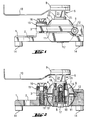
- the fastener shown in Figs. 1 to 3 is not used to determine shown guide rails on the surface of a substrate, which also with Tools not shown is edited, which can be moved along the guide rail are.
- the fastening element has a base element 1, which for better support the surface of a component, not shown, is provided with support elements which Have contact surfaces 14. On the base element 1 there are for example 4 support elements arranged, of which only two are visible.
- the basic element 1 can, for example, only be equipped with three support elements, so that one so-called "three-point support” can be achieved.
- the definition of the basic element 1 on the surface of the surface to be processed is not used
- Fastening screw shown which penetrates an elongated hole 2 in the base element 1 and can be screwed into a prepared receiving bore, also not shown, in the underground is.
- the base element 1 has on a side opposite the support surfaces 14 a substantially hemispherical receiving opening 6, which is in Tapered in the direction of the contact surfaces 14 and in which a ball 4 is arranged.
- a with the ball 4 cooperating with the base element 1 in connection Clamping element 3 serves to clamp ball 4 between base element 1 and the clamping element 3.
- the clamping element 3 also has, like the basic element 1 a semi-circular receiving opening 6, which is in one of the support surfaces 14 opposite direction tapers.
- the clamping element 3 and the base element 1 are pivotally connected to one another by means of an axis of rotation 12, the central longitudinal axis thereof runs parallel to the contact surfaces 14. The exact position of this axis of rotation is shown in in a later section.
- the surface of the clamping element 3 is, for example, one of two disks existing compensating element 15 is arranged. With the help of this compensating element 15 is a good support of the head of the screw 16 on the clamping element 3 itself then ensured when the clamping element 3 opposite one of the support surfaces 14 formed plane is arranged inclined.
- the ball 4 has a counter bearing 8 in the form of a cylindrical through hole, which widens step-wise in the direction of the contact surfaces 14. From two each other opposite sides protrudes each with a flange-like collar Bearing bushing 18, 19 in that part of the through hole that has the smaller diameter having. Between the spaced-apart bearing bushes, the Through hole an additional radial extension in the form of an undercut 13 on.
- the bearing bushes 18, 19 are used to support a connecting element 5, which penetrates both bearing bushes 18, 19 with a bearing 7, wherein the free end of the bearing 7 and the step-shaped transition of the through hole 8 are in the same plane.
- a threaded hole extends from the free end of the bearing point 7 into the connecting element 5, in which a screw 17 is screwed, the head of which is below Intermediate layer of a washer on one of the step-shaped transition of Through hole formed, the bearing surfaces 14 facing, annular Supports the abutment surface.
- the outside diameter of the bearing point 7 corresponds to that Inner diameter of the bearing bushes 18, 19 and the outer diameter of the bearing bushes 18, 19 corresponds to the smaller diameter of the ball 4 penetrating centrally Through hole.
- the eccentric cross-sectional area in one is perpendicular to the central longitudinal axis of the bearing 7 plane.
- the eccentric 9 has two spaced apart parallel to each other and parallel to Center lateral axis of the bearing point 7 extending, straight side surfaces.
- a pivot lever closes directly on the eccentric 9 10 on, the free end in a direction facing away from the support surfaces 14 is bent at right angles.
- This bent free end of the pivot lever 10 is for example provided with a locking contour, not shown, with whose help the eccentric 9 in a guide rail, not shown in the clamped position can be locked by the locking contour with positive the guide rail interacts.
- a wrench size 21 adjoins the swivel lever 10, via which the entire connecting element 5 with a suitable fork bowl, not shown is rotatable.
- the ball 4 points in a plane that is perpendicular to the central longitudinal axis of the counter bearing 8 runs and in which the ball 4 has the largest cross-sectional area, one circumferential trained recess 11 on the outer contour.
- the axis of rotation 12 extends essentially tangentially to the depression 11 the ball 4 and parallel to the bearing surfaces 14 through the base element 1 and the Clamping element 3 and protrudes laterally into the recess 11 of the ball 4.
- That area of the axis of rotation 12 which projects into the recess 11 is one-sided Provide recess 20.
- the recess 20 can be aligned towards the recess 11 so that the axis of rotation 12 no longer into this recess 11 protrudes.
- the ball 4 can now be pivoted into a position are in which the central longitudinal axis of the thrust bearing 8 is no longer perpendicular to one of the support surfaces 14 formed plane extends.
Landscapes
- Engineering & Computer Science (AREA)
- General Engineering & Computer Science (AREA)
- Mechanical Engineering (AREA)
- Pivots And Pivotal Connections (AREA)
- Processing Of Stones Or Stones Resemblance Materials (AREA)
- Polishing Bodies And Polishing Tools (AREA)
- Thermotherapy And Cooling Therapy Devices (AREA)
- Perforating, Stamping-Out Or Severing By Means Other Than Cutting (AREA)
- Finish Polishing, Edge Sharpening, And Grinding By Specific Grinding Devices (AREA)
- Clamps And Clips (AREA)
- Harvester Elements (AREA)
Priority Applications (1)
| Application Number | Priority Date | Filing Date | Title |
|---|---|---|---|
| DK00810357T DK1055831T3 (da) | 1999-05-07 | 2000-04-26 | Skinnefod til diamantskæresystem |
Applications Claiming Priority (2)
| Application Number | Priority Date | Filing Date | Title |
|---|---|---|---|
| DE19921148A DE19921148A1 (de) | 1999-05-07 | 1999-05-07 | Schienenfuß für ein Diamantschneidesystem |
| DE19921148 | 1999-05-07 |
Publications (2)
| Publication Number | Publication Date |
|---|---|
| EP1055831A1 true EP1055831A1 (fr) | 2000-11-29 |
| EP1055831B1 EP1055831B1 (fr) | 2004-11-24 |
Family
ID=7907340
Family Applications (1)
| Application Number | Title | Priority Date | Filing Date |
|---|---|---|---|
| EP00810357A Expired - Lifetime EP1055831B1 (fr) | 1999-05-07 | 2000-04-26 | Patin de rail pour système de coupe de diamant |
Country Status (8)
| Country | Link |
|---|---|
| US (1) | US6361238B1 (fr) |
| EP (1) | EP1055831B1 (fr) |
| JP (1) | JP4531928B2 (fr) |
| AT (1) | ATE283432T1 (fr) |
| DE (2) | DE19921148A1 (fr) |
| DK (1) | DK1055831T3 (fr) |
| ES (1) | ES2231143T3 (fr) |
| PL (1) | PL195730B1 (fr) |
Families Citing this family (19)
| Publication number | Priority date | Publication date | Assignee | Title |
|---|---|---|---|---|
| US6746173B2 (en) * | 2001-04-25 | 2004-06-08 | Japan Servo Co., Ltd. | Universal joint |
| GB0117098D0 (en) * | 2001-07-13 | 2001-09-05 | Renishaw Plc | Pivot joint |
| US7241070B2 (en) * | 2001-07-13 | 2007-07-10 | Renishaw Plc | Pivot joint |
| DE20205827U1 (de) * | 2002-04-15 | 2003-08-28 | Kreul, Stephan, Dipl.-Ing., 46147 Oberhausen | Halterungsvorrichtung zur Halterung von Wandanbauteilen o.dgl. |
| US20050244214A1 (en) * | 2002-07-08 | 2005-11-03 | Kilburn Kip K | Vehicle suspension system |
| US20040066015A1 (en) * | 2002-07-08 | 2004-04-08 | Kip Kilburn | Vehicle suspension system |
| US6918722B1 (en) | 2004-02-27 | 2005-07-19 | Valeda Company Llc | Double plunger track fitting |
| US7637705B2 (en) * | 2004-02-27 | 2009-12-29 | Valeda Company | Track fitting with visual indicia of engagement |
| US7229238B2 (en) * | 2004-03-25 | 2007-06-12 | Valeda Company Llc | Wheelchair docking system |
| ITPD20050143A1 (it) * | 2005-05-18 | 2006-11-19 | Lino Manfrotto & Co Spa | Supporto per attrezzature video fotografiche |
| US7665939B1 (en) | 2006-08-10 | 2010-02-23 | Sure—Lok, Inc. | Retractor anchor with top release |
| US20110097177A1 (en) * | 2009-10-28 | 2011-04-28 | Carnevali Jeffrey D | Ball mount having center fastener |
| CN103047517A (zh) * | 2012-12-27 | 2013-04-17 | 中山日高精密工业有限公司 | 一种新型云台结构 |
| FR3001713B1 (fr) * | 2013-02-05 | 2016-07-15 | Astrium Sas | Dispositif de retenue d'un reservoir dans un aeronef |
| FR3001714B1 (fr) * | 2013-02-05 | 2016-08-26 | Astrium Sas | Dispositif de support et de maintien de reservoirs cryogeniques |
| US20150314386A1 (en) * | 2014-05-05 | 2015-11-05 | GM Global Technology Operations LLC | Adaptor for a tool or handle |
| ITUA20162560A1 (it) * | 2016-04-13 | 2017-10-13 | Vitec Imaging Solutions S P A | Modulo orientabile per apparecchiature video-fotografiche |
| USD847036S1 (en) | 2017-02-02 | 2019-04-30 | Aircraft Gear Corporation | Tie rod end |
| USD847696S1 (en) | 2017-02-02 | 2019-05-07 | Aircraft Gear Corporation | Tie rod connector |
Citations (6)
| Publication number | Priority date | Publication date | Assignee | Title |
|---|---|---|---|---|
| DE2112431A1 (de) * | 1970-03-17 | 1971-10-07 | Eliny Plast Ab | Gelenk |
| FR2548746A1 (fr) * | 1983-07-04 | 1985-01-11 | Thomson Brandt | Articulation a rotule immobilisable a l'aide d'un seul element de blocage |
| US4515336A (en) * | 1983-04-14 | 1985-05-07 | Opcon, Inc. | Ball and socket mount for optical sensing system source and/or detector devices |
| US4796508A (en) * | 1986-07-31 | 1989-01-10 | Hoshino Gakki Co., Ltd. | Musical instrument support fixture |
| WO1990014031A1 (fr) * | 1989-05-19 | 1990-11-29 | Tridec Iii Corporation | Chaise pivotante a siege inclinable et mecanisme prevu a cet effet |
| DE9301268U1 (de) * | 1993-01-30 | 1993-03-11 | Fa. Carl Zeiss, 7920 Heidenheim | Gelenkige Aufhängung |
Family Cites Families (7)
| Publication number | Priority date | Publication date | Assignee | Title |
|---|---|---|---|---|
| US2664029A (en) * | 1951-04-07 | 1953-12-29 | Richard L Higgins | Remotely adjustable rearview mirror |
| US4026657A (en) * | 1974-09-05 | 1977-05-31 | Textron, Inc. | Sintered spherical articles |
| DE3225052A1 (de) * | 1982-07-05 | 1984-01-05 | Hilti AG, 9494 Schaan | Widerlager mit dem aufbringen eines drehmomentes dienendem betaetigungsorgan fuer gewindebolzen |
| DE3344064A1 (de) * | 1983-12-06 | 1985-07-04 | Hilti Ag, Schaan | Haltevorrichtung fuer bohrgeraete |
| DE3719164A1 (de) * | 1987-06-09 | 1988-12-29 | Hilti Ag | Spreizduebel mit begrenzter spreizung |
| DE4333913C2 (de) * | 1992-10-09 | 1997-11-20 | Link Johs Sonor Gmbh | Einstellvorrichtung an längen- und/oder neigungsverstellbaren Haltern, insbesondere für Percussions-Musikinstrumente |
| US5899167A (en) * | 1997-08-11 | 1999-05-04 | Furman; Shulim | Display support device for displaying replaceable indicia |
-
1999
- 1999-05-07 DE DE19921148A patent/DE19921148A1/de not_active Withdrawn
-
2000
- 2000-03-23 US US09/533,475 patent/US6361238B1/en not_active Expired - Lifetime
- 2000-04-26 ES ES00810357T patent/ES2231143T3/es not_active Expired - Lifetime
- 2000-04-26 AT AT00810357T patent/ATE283432T1/de active
- 2000-04-26 DK DK00810357T patent/DK1055831T3/da active
- 2000-04-26 EP EP00810357A patent/EP1055831B1/fr not_active Expired - Lifetime
- 2000-04-26 DE DE50008721T patent/DE50008721D1/de not_active Expired - Lifetime
- 2000-05-05 PL PL340001A patent/PL195730B1/pl unknown
- 2000-05-08 JP JP2000134795A patent/JP4531928B2/ja not_active Expired - Fee Related
Patent Citations (6)
| Publication number | Priority date | Publication date | Assignee | Title |
|---|---|---|---|---|
| DE2112431A1 (de) * | 1970-03-17 | 1971-10-07 | Eliny Plast Ab | Gelenk |
| US4515336A (en) * | 1983-04-14 | 1985-05-07 | Opcon, Inc. | Ball and socket mount for optical sensing system source and/or detector devices |
| FR2548746A1 (fr) * | 1983-07-04 | 1985-01-11 | Thomson Brandt | Articulation a rotule immobilisable a l'aide d'un seul element de blocage |
| US4796508A (en) * | 1986-07-31 | 1989-01-10 | Hoshino Gakki Co., Ltd. | Musical instrument support fixture |
| WO1990014031A1 (fr) * | 1989-05-19 | 1990-11-29 | Tridec Iii Corporation | Chaise pivotante a siege inclinable et mecanisme prevu a cet effet |
| DE9301268U1 (de) * | 1993-01-30 | 1993-03-11 | Fa. Carl Zeiss, 7920 Heidenheim | Gelenkige Aufhängung |
Also Published As
| Publication number | Publication date |
|---|---|
| DK1055831T3 (da) | 2005-04-04 |
| DE50008721D1 (de) | 2004-12-30 |
| ES2231143T3 (es) | 2005-05-16 |
| JP4531928B2 (ja) | 2010-08-25 |
| PL195730B1 (pl) | 2007-10-31 |
| DE19921148A1 (de) | 2000-11-09 |
| US6361238B1 (en) | 2002-03-26 |
| ATE283432T1 (de) | 2004-12-15 |
| JP2000334730A (ja) | 2000-12-05 |
| PL340001A1 (en) | 2000-11-20 |
| EP1055831B1 (fr) | 2004-11-24 |
Similar Documents
| Publication | Publication Date | Title |
|---|---|---|
| EP1055831B1 (fr) | Patin de rail pour système de coupe de diamant | |
| EP0563542B1 (fr) | Moyens pour connecter des pièces de façon détachable | |
| EP0324022A1 (fr) | Dispositif de positionnement | |
| CH680839A5 (fr) | ||
| EP2070440A1 (fr) | Table, notamment table pour la position debout ou de bistrot | |
| AT401080B (de) | Halter für die biegemomentfreie lagerung von glasplatten | |
| EP1726403A2 (fr) | Levier avec butée reglable en hauteur | |
| EP2097199B1 (fr) | Dispositif pendulaire et procédé associé | |
| AT393797B (de) | Bindung fuer snowboards | |
| DE60219018T2 (de) | Gelenkverbindung | |
| DE19821924C2 (de) | Gartenschere mit einem Schneidblatt und einem hiermit zusammenwirkenden Amboß | |
| DE69301591T2 (de) | Befestigungs- und Schwenkeinrichtung für eine über einer Grundplatte befindlichen Vorrichtung | |
| WO2013156471A1 (fr) | Écrou à tête pivotante | |
| DE2721107A1 (de) | Vorrichtung zur verbindung eines arbeitswerkzeuges an einem tragarm, insbesondere an einem holm | |
| EP0157890A1 (fr) | Outil de coupe avec tête de coupe et tige d'accouplement | |
| DE4240361C2 (de) | Dreidimensional einstellbares Kraftwagentürscharnier | |
| DE69517190T2 (de) | Gleitschutzvorrichtung | |
| DE1958554B2 (de) | Schneidwerkzeug fur spanabhebende Bearbeitung | |
| DE3102800C2 (de) | Spannvorrichtung zum Festspannen von Werkstücken auf dem Tisch od.dgl. einer Werkzeugmaschine | |
| DE102004024945B4 (de) | Feststellbarer Schnellverstellzirkel | |
| DE202004000843U1 (de) | Schraubenschlüssel | |
| DE202024107096U1 (de) | Handschleifer zum Schleifen von Wandoberflächen an Ecken zwischen zwei Wänden | |
| DE202005012422U1 (de) | Verbindungselement, insbesondere für Handläufe | |
| DE9216325U1 (de) | Dreidimensional einstellbares Kraftwagentürscharnier | |
| DE202022107088U1 (de) | Schraubenschlüsselkörperstruktur |
Legal Events
| Date | Code | Title | Description |
|---|---|---|---|
| PUAI | Public reference made under article 153(3) epc to a published international application that has entered the european phase |
Free format text: ORIGINAL CODE: 0009012 |
|
| AK | Designated contracting states |
Kind code of ref document: A1 Designated state(s): AT BE CH CY DE DK ES FI FR GB GR IE IT LI LU MC NL PT SE |
|
| AX | Request for extension of the european patent |
Free format text: AL;LT;LV;MK;RO;SI |
|
| 17P | Request for examination filed |
Effective date: 20010529 |
|
| AKX | Designation fees paid |
Free format text: AT BE CH CY DE DK ES FI FR GB GR IE IT LI LU MC NL PT SE |
|
| GRAP | Despatch of communication of intention to grant a patent |
Free format text: ORIGINAL CODE: EPIDOSNIGR1 |
|
| RIC1 | Information provided on ipc code assigned before grant |
Ipc: 7F 16M 11/14 B Ipc: 7F 16C 11/10 A |
|
| GRAS | Grant fee paid |
Free format text: ORIGINAL CODE: EPIDOSNIGR3 |
|
| GRAA | (expected) grant |
Free format text: ORIGINAL CODE: 0009210 |
|
| AK | Designated contracting states |
Kind code of ref document: B1 Designated state(s): AT BE CH CY DE DK ES FI FR GB GR IE IT LI LU MC NL PT SE |
|
| PG25 | Lapsed in a contracting state [announced via postgrant information from national office to epo] |
Ref country code: IE Free format text: LAPSE BECAUSE OF FAILURE TO SUBMIT A TRANSLATION OF THE DESCRIPTION OR TO PAY THE FEE WITHIN THE PRESCRIBED TIME-LIMIT Effective date: 20041124 Ref country code: FI Free format text: LAPSE BECAUSE OF FAILURE TO SUBMIT A TRANSLATION OF THE DESCRIPTION OR TO PAY THE FEE WITHIN THE PRESCRIBED TIME-LIMIT Effective date: 20041124 |
|
| REG | Reference to a national code |
Ref country code: GB Ref legal event code: FG4D Free format text: NOT ENGLISH |
|
| REG | Reference to a national code |
Ref country code: SE Ref legal event code: TRGR Ref country code: CH Ref legal event code: EP |
|
| REF | Corresponds to: |
Ref document number: 50008721 Country of ref document: DE Date of ref document: 20041230 Kind code of ref document: P |
|
| REG | Reference to a national code |
Ref country code: IE Ref legal event code: FG4D Free format text: GERMAN |
|
| GBT | Gb: translation of ep patent filed (gb section 77(6)(a)/1977) |
Effective date: 20050202 |
|
| PG25 | Lapsed in a contracting state [announced via postgrant information from national office to epo] |
Ref country code: GR Free format text: LAPSE BECAUSE OF FAILURE TO SUBMIT A TRANSLATION OF THE DESCRIPTION OR TO PAY THE FEE WITHIN THE PRESCRIBED TIME-LIMIT Effective date: 20050224 |
|
| REG | Reference to a national code |
Ref country code: DK Ref legal event code: T3 |
|
| PGFP | Annual fee paid to national office [announced via postgrant information from national office to epo] |
Ref country code: IE Payment date: 20050414 Year of fee payment: 6 |
|
| PG25 | Lapsed in a contracting state [announced via postgrant information from national office to epo] |
Ref country code: CY Free format text: LAPSE BECAUSE OF FAILURE TO SUBMIT A TRANSLATION OF THE DESCRIPTION OR TO PAY THE FEE WITHIN THE PRESCRIBED TIME-LIMIT Effective date: 20050426 Ref country code: LU Free format text: LAPSE BECAUSE OF NON-PAYMENT OF DUE FEES Effective date: 20050426 |
|
| PG25 | Lapsed in a contracting state [announced via postgrant information from national office to epo] |
Ref country code: MC Free format text: LAPSE BECAUSE OF NON-PAYMENT OF DUE FEES Effective date: 20050430 |
|
| REG | Reference to a national code |
Ref country code: ES Ref legal event code: FG2A Ref document number: 2231143 Country of ref document: ES Kind code of ref document: T3 |
|
| REG | Reference to a national code |
Ref country code: IE Ref legal event code: FD4D |
|
| PLBE | No opposition filed within time limit |
Free format text: ORIGINAL CODE: 0009261 |
|
| STAA | Information on the status of an ep patent application or granted ep patent |
Free format text: STATUS: NO OPPOSITION FILED WITHIN TIME LIMIT |
|
| ET | Fr: translation filed | ||
| 26N | No opposition filed |
Effective date: 20050825 |
|
| PG25 | Lapsed in a contracting state [announced via postgrant information from national office to epo] |
Ref country code: PT Free format text: LAPSE BECAUSE OF NON-PAYMENT OF DUE FEES Effective date: 20050424 |
|
| REG | Reference to a national code |
Ref country code: FR Ref legal event code: PLFP Year of fee payment: 17 |
|
| REG | Reference to a national code |
Ref country code: FR Ref legal event code: PLFP Year of fee payment: 18 |
|
| REG | Reference to a national code |
Ref country code: FR Ref legal event code: PLFP Year of fee payment: 19 |
|
| PGFP | Annual fee paid to national office [announced via postgrant information from national office to epo] |
Ref country code: NL Payment date: 20180418 Year of fee payment: 19 |
|
| PGFP | Annual fee paid to national office [announced via postgrant information from national office to epo] |
Ref country code: ES Payment date: 20180525 Year of fee payment: 19 Ref country code: CH Payment date: 20180419 Year of fee payment: 19 Ref country code: DE Payment date: 20180420 Year of fee payment: 19 Ref country code: DK Payment date: 20180418 Year of fee payment: 19 |
|
| PGFP | Annual fee paid to national office [announced via postgrant information from national office to epo] |
Ref country code: MC Payment date: 20170828 Year of fee payment: 10 Ref country code: FR Payment date: 20180420 Year of fee payment: 19 Ref country code: BE Payment date: 20180418 Year of fee payment: 19 |
|
| PGFP | Annual fee paid to national office [announced via postgrant information from national office to epo] |
Ref country code: SE Payment date: 20180418 Year of fee payment: 19 |
|
| PGFP | Annual fee paid to national office [announced via postgrant information from national office to epo] |
Ref country code: GB Payment date: 20180418 Year of fee payment: 19 |
|
| PGFP | Annual fee paid to national office [announced via postgrant information from national office to epo] |
Ref country code: IT Payment date: 20190429 Year of fee payment: 20 |
|
| REG | Reference to a national code |
Ref country code: DE Ref legal event code: R119 Ref document number: 50008721 Country of ref document: DE |
|
| REG | Reference to a national code |
Ref country code: CH Ref legal event code: PL |
|
| REG | Reference to a national code |
Ref country code: DK Ref legal event code: EBP Effective date: 20190430 |
|
| REG | Reference to a national code |
Ref country code: SE Ref legal event code: EUG |
|
| REG | Reference to a national code |
Ref country code: NL Ref legal event code: MM Effective date: 20190501 |
|
| REG | Reference to a national code |
Ref country code: AT Ref legal event code: MM01 Ref document number: 283432 Country of ref document: AT Kind code of ref document: T Effective date: 20190426 |
|
| REG | Reference to a national code |
Ref country code: BE Ref legal event code: MM Effective date: 20190430 |
|
| GBPC | Gb: european patent ceased through non-payment of renewal fee |
Effective date: 20190426 |
|
| PG25 | Lapsed in a contracting state [announced via postgrant information from national office to epo] |
Ref country code: NL Free format text: LAPSE BECAUSE OF NON-PAYMENT OF DUE FEES Effective date: 20190501 Ref country code: DE Free format text: LAPSE BECAUSE OF NON-PAYMENT OF DUE FEES Effective date: 20191101 Ref country code: GB Free format text: LAPSE BECAUSE OF NON-PAYMENT OF DUE FEES Effective date: 20190426 Ref country code: AT Free format text: LAPSE BECAUSE OF NON-PAYMENT OF DUE FEES Effective date: 20190426 Ref country code: LI Free format text: LAPSE BECAUSE OF NON-PAYMENT OF DUE FEES Effective date: 20190430 Ref country code: CH Free format text: LAPSE BECAUSE OF NON-PAYMENT OF DUE FEES Effective date: 20190430 Ref country code: SE Free format text: LAPSE BECAUSE OF NON-PAYMENT OF DUE FEES Effective date: 20190427 |
|
| PG25 | Lapsed in a contracting state [announced via postgrant information from national office to epo] |
Ref country code: BE Free format text: LAPSE BECAUSE OF NON-PAYMENT OF DUE FEES Effective date: 20190430 |
|
| PG25 | Lapsed in a contracting state [announced via postgrant information from national office to epo] |
Ref country code: DK Free format text: LAPSE BECAUSE OF NON-PAYMENT OF DUE FEES Effective date: 20190430 |
|
| PG25 | Lapsed in a contracting state [announced via postgrant information from national office to epo] |
Ref country code: FR Free format text: LAPSE BECAUSE OF NON-PAYMENT OF DUE FEES Effective date: 20190430 |
|
| REG | Reference to a national code |
Ref country code: ES Ref legal event code: FD2A Effective date: 20200901 |
|
| PG25 | Lapsed in a contracting state [announced via postgrant information from national office to epo] |
Ref country code: ES Free format text: LAPSE BECAUSE OF NON-PAYMENT OF DUE FEES Effective date: 20190427 |