EP1055854A2 - Electrovanne à structure monolithique en matériau ferromagnétique - Google Patents
Electrovanne à structure monolithique en matériau ferromagnétique Download PDFInfo
- Publication number
- EP1055854A2 EP1055854A2 EP00440093A EP00440093A EP1055854A2 EP 1055854 A2 EP1055854 A2 EP 1055854A2 EP 00440093 A EP00440093 A EP 00440093A EP 00440093 A EP00440093 A EP 00440093A EP 1055854 A2 EP1055854 A2 EP 1055854A2
- Authority
- EP
- European Patent Office
- Prior art keywords
- monolithic structure
- solenoid valve
- cavity
- core
- intake
- Prior art date
- Legal status (The legal status is an assumption and is not a legal conclusion. Google has not performed a legal analysis and makes no representation as to the accuracy of the status listed.)
- Granted
Links
- 239000003302 ferromagnetic material Substances 0.000 title claims abstract description 17
- 239000012530 fluid Substances 0.000 claims abstract description 25
- 238000006073 displacement reaction Methods 0.000 claims abstract description 6
- 238000001914 filtration Methods 0.000 claims description 3
- 238000009434 installation Methods 0.000 claims 1
- ZPEZUAAEBBHXBT-WCCKRBBISA-N (2s)-2-amino-3-methylbutanoic acid;2-amino-3-methylbutanoic acid Chemical compound CC(C)C(N)C(O)=O.CC(C)[C@H](N)C(O)=O ZPEZUAAEBBHXBT-WCCKRBBISA-N 0.000 abstract 1
- 230000000903 blocking effect Effects 0.000 abstract 1
- 230000005291 magnetic effect Effects 0.000 description 28
- 238000004804 winding Methods 0.000 description 18
- 230000005294 ferromagnetic effect Effects 0.000 description 10
- 239000000463 material Substances 0.000 description 5
- XEEYBQQBJWHFJM-UHFFFAOYSA-N Iron Chemical compound [Fe] XEEYBQQBJWHFJM-UHFFFAOYSA-N 0.000 description 4
- 239000000806 elastomer Substances 0.000 description 4
- 229920001971 elastomer Polymers 0.000 description 4
- 230000005284 excitation Effects 0.000 description 4
- 239000007788 liquid Substances 0.000 description 4
- 239000002184 metal Substances 0.000 description 4
- 229910052751 metal Inorganic materials 0.000 description 4
- 238000007789 sealing Methods 0.000 description 4
- 239000004020 conductor Substances 0.000 description 3
- 230000000694 effects Effects 0.000 description 2
- 229910052742 iron Inorganic materials 0.000 description 2
- 238000004519 manufacturing process Methods 0.000 description 2
- 239000007787 solid Substances 0.000 description 2
- RYGMFSIKBFXOCR-UHFFFAOYSA-N Copper Chemical compound [Cu] RYGMFSIKBFXOCR-UHFFFAOYSA-N 0.000 description 1
- 238000004026 adhesive bonding Methods 0.000 description 1
- 239000000443 aerosol Substances 0.000 description 1
- 238000010276 construction Methods 0.000 description 1
- 238000001816 cooling Methods 0.000 description 1
- 229910052802 copper Inorganic materials 0.000 description 1
- 239000010949 copper Substances 0.000 description 1
- 230000004907 flux Effects 0.000 description 1
- 239000003292 glue Substances 0.000 description 1
- 230000006698 induction Effects 0.000 description 1
- 239000011810 insulating material Substances 0.000 description 1
- 239000012212 insulator Substances 0.000 description 1
- 230000007257 malfunction Effects 0.000 description 1
- 230000035699 permeability Effects 0.000 description 1
- 230000003252 repetitive effect Effects 0.000 description 1
- 229910000679 solder Inorganic materials 0.000 description 1
- 239000007921 spray Substances 0.000 description 1
- 238000005507 spraying Methods 0.000 description 1
- 238000003466 welding Methods 0.000 description 1
Images


Classifications
-
- F—MECHANICAL ENGINEERING; LIGHTING; HEATING; WEAPONS; BLASTING
- F16—ENGINEERING ELEMENTS AND UNITS; GENERAL MEASURES FOR PRODUCING AND MAINTAINING EFFECTIVE FUNCTIONING OF MACHINES OR INSTALLATIONS; THERMAL INSULATION IN GENERAL
- F16K—VALVES; TAPS; COCKS; ACTUATING-FLOATS; DEVICES FOR VENTING OR AERATING
- F16K31/00—Actuating devices; Operating means; Releasing devices
- F16K31/02—Actuating devices; Operating means; Releasing devices electric; magnetic
- F16K31/06—Actuating devices; Operating means; Releasing devices electric; magnetic using a magnet, e.g. diaphragm valves, cutting off by means of a liquid
- F16K31/0644—One-way valve
- F16K31/0655—Lift valves
-
- F—MECHANICAL ENGINEERING; LIGHTING; HEATING; WEAPONS; BLASTING
- F16—ENGINEERING ELEMENTS AND UNITS; GENERAL MEASURES FOR PRODUCING AND MAINTAINING EFFECTIVE FUNCTIONING OF MACHINES OR INSTALLATIONS; THERMAL INSULATION IN GENERAL
- F16K—VALVES; TAPS; COCKS; ACTUATING-FLOATS; DEVICES FOR VENTING OR AERATING
- F16K31/00—Actuating devices; Operating means; Releasing devices
- F16K31/02—Actuating devices; Operating means; Releasing devices electric; magnetic
- F16K31/06—Actuating devices; Operating means; Releasing devices electric; magnetic using a magnet, e.g. diaphragm valves, cutting off by means of a liquid
- F16K31/0644—One-way valve
- F16K31/0651—One-way valve the fluid passing through the solenoid coil
Definitions
- the present invention relates to a new structure solenoid valve. It relates more particularly to a miniature solenoid valve, intended to be supplied under low voltage, notably by means of an autonomous energy source, battery or battery type.
- the invention finds its application in all areas where it is useful to block or leave circulate a fluid (liquid or gas), and for example, but not exclusively pressurized fluid.
- the miniature solenoid valves currently available on the market usually include a solenoid valve body, which is usually plastic, which is associated with a valve and in which an intake duct and a duct are provided exhaust of a fluid. These two intake ducts and exhaust lead into an open cavity of the body of the solenoid valve, the cavity in which the seat of the valve.
- the valve is in the form of a movable core in translation between two positions: a closed position of the solenoid valve in which the core is applied against the valve seat so as to block the inlet of the duct exhaust, and prevent any circulation of a fluid between the intake duct and the exhaust duct; a position opening of the solenoid valve in which the core is not in contact with the valve seat, a fluid can thus circulate between the intake duct and the duct exhaust.
- the face of the core that comes into contact with the valve seat is provided with an elastomeric pad.
- the displacement of the core between the closed positions and opening of the solenoid valve is controlled by means electromagnetic.
- the core cooperates with a return spring which returns it to its closed position, in the absence of solicitation of electromagnetic means, and electromagnetic means, when requested, cause the displacement of the valve core and its holding the solenoid valve in the open position.
- the coil is made using one or more wires electrically conductive which are wound on a carcass cylindrical, and which are intended to be supplied by a Electric power.
- the cylindrical carcass is hollow by being open at both ends, and is made of a material insulator, such as for example plastic.
- One of the two open ends of the carcass is positioned opposite from the seat of the solenoid valve, the other end open being sealed off by an attached plug.
- the valve-like core is partly housed in the carcass cylindrical.
- the solenoid valve magnetic circuit is generally made of three separate pieces of material ferromagnetic, for example in soft iron: the aforementioned plug, a U-shaped frame, the base of which comes into contact with the plug and the two branches of which extend substantially parallel to the axis of the coil, and a ring which connects the two branches of the U-shaped frame, which is applied against the open open end of the coil carcass, and which is crossed by the valve function core.
- the above-mentioned solenoid valves have a relatively complex structure, which makes their manufacture expensive. Also the sealing of these solenoid valves, which is essential to avoid any leakage of the fluid circulating in the solenoid valve, is difficult to achieve and requires the use of three seals: a first seal mounted on the periphery of the plug the magnetic circuit for sealing between this plug and the coil carcass; a second seal ensuring the seal between the carcass of the coil and the ring of the magnetic circuit; a third seal ensuring the seal between the ring of the magnetic circuit and the body of the solenoid valve.
- the volume available for the coil is low, and what is more this coil is generally supplied with a current of low intensity delivered for example by a battery.
- the magnetic field created by the coil is weak and allows the solenoid valve to operate with a maximum stroke of the core with valve function, which is small and which is typically less than 0.25 mm.
- the elastomeric pad of the core tends to deform by becoming hollow under the effect of repetitive contacts with the seat of the valve, which has the effect over time of increase the core stroke. It may happen that this stroke becomes greater than the maximum authorized stroke for the core, which in this case results in a malfunction of the solenoid valve.
- the subject of the invention is a new solenoid valve structure. which has the particular advantage of simplifying the construction and obtaining of the sealing of the solenoid valve, and which in addition, compared to the aforementioned solenoid valves of the prior art, allows to obtain for the order of the displacement of the nucleus, a more intense magnetic field high, and thereby increase the maximum allowed travel for the nucleus.
- the frame which allows with the monolithic structure to form a closed magnetic circuit can be permanently fixed to the monolithic structure, or be separated and provided in the system using the solenoid valve, by example in the form of a base in contact with which one comes apply the polar ends of the monolithic structure during the implementation of the solenoid valve.
- the monolithic structure serves as the times of coil carcass while being part of the circuit solenoid valve. Since in the solenoid valve of the invention, the coil carcass is in ferromagnetic material, on the one hand when feeding the coil wire, the magnetic field created by the wound wire induced, in the monolithic structure in material ferromagnetic, an additional magnetic field that comes add to the magnetic field of the coil. On the other hand we reduces the air gap between the core and the coil winding compared to prior art solenoid valves previously described.
- a metal core 4 to valve function which rests on the bottom 25 of the cavity 21, via a return spring R.
- the rear part 40 of the core has a diameter lower and is threaded on the spring R, and the front part 41 of the core forms, with respect to the rear part 40 a shoulder on which the return spring comes to bear A.
- a buffer elastomer T On the front face 42 of the core 4 is provided a buffer elastomer T which is fixed, for example by being glued, in a recess provided in the front face 42 of the core 4.
- the second part 3 made of ferromagnetic material is presented under the shape of a solid piece of parallelepiped shape.
- a small cavity open 31 of circular shape In one of the faces 30 of this part 3 is formed a small cavity open 31 of circular shape, the bottom 6a of which forms at the level from the center of the cavity a projecting part 33 intended for form the valve seat.
- this room 3 are further formed two conduits 34 and 35 for circulation of a fluid.
- the duct 34 is straight, crosses part by part part 3, and opens at its end 340 to inside the cavity 31 of the part 3 and at its end opposite 341 in the upper face 37 of the part 3.
- the conduit 35 is a straight pipe which also passes through the part 3, and which opens at a first end 350 at the top of the seat valve 33 and at its opposite end 351 in the rear face 36 of Exhibit 3.
- the core 4 with valve function and its spring R are introduced into the cavity 21 of the cylindrical portion 20 of the part 2.
- the parts 2 are assembled and 3 by fixing one against the other, for example by gluing or by welding, the front face 23 of the cylindrical portion 20 and the front face 30 of part 3, ensuring that the connection between the two parts 2 and 3 is perfectly waterproof.
- Exhibit 3 is positioned in relation to part 2 so that the interior cavity 21 and interior cavity 31 are located in the extension of each other, and that the top of the seat 33 of the valve comes into contact with the elastomer pad T of the core 4.
- the outer periphery of the cylindrical portion 20 comprises a winding 5 of at least one electrically conductive wire 5 forming a plurality of turns preferably contiguous and superimposed.
- the conductor wire (s) of the winding 5 consist for example of one or more copper wires enameled.
- This winding 5 forms with the cylindrical portion 20 a coil whose carcass constituted by the portion cylindrical 20 is made of ferromagnetic material.
- the winding conductor 5 is intended to be supplied with current, by example by means of an autonomous voltage source, of the battery type allowing a low DC voltage to be applied to both ends of the wire or wires constituting the conductive winding 5 and generate a current in the coil winding.
- one of the two ends of the wire or wires will be welded directly to part 2, the monolithic structure consisting of parts 2 and 3 acting as a mass.
- a ferromagnetic armature A is provided, form of plaque in the illustrated copy, which combines the two polar ends of the monolithic structure, i.e. in the example of FIG. 1, part 3 at the rear part 24 of part 2.
- This frame A can be fixed so definitive on the monolithic structure of the solenoid valve. In a variant, this frame may not be permanently fixed on the monolithic structure, but can be integrated into the system using the solenoid valve, for example forming a base on which we just adapt the monolithic structure of Figure 1.
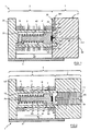
- the operation of the solenoid valve 1 is as follows. In no excitation current in the conductor winding 5, the core 4 with valve function is in the position illustrated in Figure 1, called the closed position of the solenoid valve. In this position, the head 41 of the core 4 is kept applied, by the return force of the spring R, against the seat 33 of the valve, the elastomeric buffer T closing off tightly the orifice 350 of the conduit 35. In this position, no fluid (liquid or gas) can circulate at inside the solenoid valve between the two conduits 34 and 35. It should be noted that conduits 34 and 35 can either act as an intake duct or fluid exhaust.
- the magnetic field created by the coil and that induced in the coil carcass made of ferromagnetic material polarize the monolithic structure and cause the core to slide 4 towards the rear, i.e. towards the rear 24, and unlike the restoring force of the spring R which therefore fact is more strongly compressed.
- the elastomer pad T leaves the seat 33 of the valve and frees the opening 350 from the conduit 35, leaving the passage of a fluid between the conduit 34 and the conduit 35 via the cavities 21 and 31.
- the solenoid valve remains in the open position.
- the carcass of the coil the solenoid valve being made of ferromagnetic material, and therefore thermally conductive, it also advantageously allows to quickly dissipate the heat given off by the passage of current in the coil winding, and thereby to ensure better cooling of the coil.
- the stroke of the core 4 which corresponds to the distance between the rear portion 40 of the core 4 of the bottom 25 of the cavity 21.
- the winding 5 of the coil is in a variant formed by three conducting wires 50, 51, 52, the external structure of which is covered with an insulating material 53 and which are intended to be supplied in parallel .
- These three wires 50, 51, 52 are advantageously twisted for a question of space.
- the resistance of the winding 5 is divided by three compared to a winding comprising the same number of turns but composed of a single wire. It follows that this type of winding 5 composed of several wires in parallel (at least two) makes it possible to create a more intense magnetic field.
- FIG. 2 differs from that of FIG. 1 essentially by the implementation of a monolithic ferromagnetic structure which is produced in a single part 6.
- This part 6 has two parts 7 and 7 '.
- Part 7 is structurally similar to part 2 of the embodiment in FIG.
- Part 7 ' has substantially the same external shape as the part 3 and has a cylindrical recess 70 'which is located in the extension and has a diameter slightly greater than that of cavity 71 in part 7.
- This obviously 70 ' has, opposite the cavity 71, an access opening 71 'allowing the introduction of the core 4 and its spring R to the interior of the monolithic structure and its placement into the cavity 71.
- 70 ′ is crimped a insert insert 8 of cylindrical shape which is for example in plastic material.
- the front face 80 of this insert reported 8 comes to bear against an intermediate shoulder between the cavity 71 and the recess 70 ', via a 72 'O-ring seal.
- the front face 80 of this insert 8 has a protruding central part 82 forming the seat of the valve.
- An intake or exhaust duct 83 is provided at central part of this insert 8.
- the conduit 83 ends with a chamber 84 substantially hemispherical, which communicates with conduit 83, which, on the other hand, is formed by a perforated surface 85.
- a perforated surface 85 When the conduit 82 is used as liquid exhaust duct, chamber 84 and surface perforated 85 form a nozzle for spraying the liquid in the form of a multitude of jets.
- the perforated wall 85 makes it possible to filter the fluid on admission.
- the conduit 76 which in this variant makes intake duct office, ends at its end 77 by an open cavity 78, inside which is mounted a filter element 79, such as for example a metallic canvas.
- the position and shape of the intake ducts and exhaust 34, 35 or 76 and 83 is not limiting of the invention. In particular the position will be chosen according to of the intended application. More particularly, in a variant it is possible to modify the embodiment of the Figure 2, using conduit 83 as conduit intermediate, this conduit 83 having for example a bent shape upwards and by making this conduit 83 communicate with a additional duct (intake or exhaust duct) formed through the part 7 '.
- Part 7 identically comprises a cylindrical part 70, a rear part 74, a cylindrical interior cavity 71, a metal core 4 comprising a rear part 40 and a front part 41, a return spring R, a front face 42 fitted with an elastomeric T buffer, an intake duct or exhaust of a fluid 76 formed in the rear part 74 and which opens into the cavity 71 at the bottom 75 of this cavity 71, and a winding 5.
- part 7 ′ it also has a cylindrical recess 70 'which extends cavity 71, however this houses the front part 41 of the metal core 4 and is closed by the part 9 which is secured tightly to part 7 ', and of which protrudes, to at least partially penetrate into obviously cylindrical 70 ', a central part 90 in which opens an intake or exhaust duct 91 and against which can abut the core 4 by through the buffer T, to form the seat of the valve.
- conduits intake and exhaust are made in room 9, one such as conduit 91, and the other opening into the cavity 70 ', opposite the central part 90.
- the part 9 can be made of a non-material ferromagnetic, and it can be secured to part 6 by collage for example.
- the invention finds its application in all areas where it is useful to regulate the circulation of a fluid. She finds more particularly but not exclusively its application to the production of pressurized aerosols incorporating solenoid valve of the invention to realize the mechanism of spray.
Landscapes
- Engineering & Computer Science (AREA)
- General Engineering & Computer Science (AREA)
- Mechanical Engineering (AREA)
- Magnetically Actuated Valves (AREA)
Abstract
- une structure monolithique en matériau ferromagnétique, et dans laquelle sont ménagés une cavité (21, 31) servant de logement au noyau (4) à fonction de clapet, et au moins l'un (34, 35) des deux conduits d'admission ou d'échappement, lequel débouche dans la cavité,
- au moins un fil (5) électriquement conducteur enroulé sur la structure monolithique, et destiné à être alimenté par un courant électrique,
- et au moins une armature (A) en matériau ferromagnétique qui relie les deux extrémités polaires (24, 3) de la structure monolithique.
Description
Dans une électrovanne miniature, le volume disponible pour la bobine est faible, et qui plus est cette bobine est généralement alimentée avec un courant de faible intensité délivré par exemple par une pile. Il en résulte que le champ magnétique créé par la bobine est faible et autorise un fonctionnement de l'électrovanne avec une course maximale du noyau à fonction de clapet, qui est faible et qui est typiquement inférieure à 0,25 mm. Or après un certain nombre de cycles de fonctionnement d'une électrovanne, le tampon élastomère du noyau a tendance à se déformer en se creusant sous l'effet des contacts répétitifs avec le siège du clapet, ce qui a pour effet dans le temps d'augmenter la course du noyau. Il peut arriver que cette course devienne supérieure à la course maximale autorisée pour le noyau, ce qui se traduit dans ce cas par un dysfonctionnement de l'électrovanne.
- un conduit d'admission et un conduit d'échappement d'un fluide.
- un noyau mobile à fonction de clapet, qui permet en fonction de sa position de bloquer ou de laisser circuler un fluide entre le conduit d'admission et le conduit d'échappement,
- et des moyens électromagnétiques qui permettent de commander le déplacement du noyau.
- une structure monolithique qui est en matériau ferromagnétique, et dans laquelle sont ménagés d'une part une cavité servant de logement au noyau à fonction de clapet et d'autre part au moins l'un des deux conduits d'admission ou d'échappement, lequel conduit débouche dans ladite cavité,
- au moins un fil électriquement conducteur qui est enroulé sur la structure monolithique, et qui est destiné à être alimenté par un courant électrique,
- et au moins une armature en matériau ferromagnétique qui relie les deux extrémités polaires de la structure monolithique.
- la figure 1 représente une vue schématique en coupe longitudinale d'un premier mode de réalisation d'une électrovanne selon l'invention, présentant une structure monolithique ferromagnétique formée par l'assemblage étanche de deux pièces,
- la figure 2 représente une vue schématique en coupe longitudinale d'un second mode de réalisation d'une électrovanne de l'invention, dans laquelle la structure monolithique ferromagnétique est réalisée en une seule pièce,
- la figure 3 représente une variante préférée de réalisation d'un enroulement multifilaire pour constituer la bobine génératrice du champ magnétique,
- la figure 4 représente une variante d'un conduit d'admission muni de moyens de filtration du fluide à l'admission,
- la figure 5 représente une vue schématique en coupe longitudinale d'une variante du second mode de réalisation d'une électrovanne selon l'invention, dans laquelle la structure monolithique ferromagnétique est réalisée en une seule pièce. En référence à la figure 1, dans un premier mode de réalisation, l'électrovanne 1 comporte une structure monolithique constituée par l'assemblage de deux pièces 2 et 3, qui sont réalisées en matériau ferromagnétique, par exemple en fer doux. La première pièce 2 comporte une première partie cylindrique 20 qui est évidée en sorte de former une cavité intérieure cylindrique 3. Cette cavité 21 présente une ouverture d'accès 22 qui est réalisée dans la face avant 23 de la partie cylindrique 20. A l'opposé de cette face avant 23, la partie cylindrique 20 se prolonge par une portion arrière 24 qui est pleine, et qui de préférence forme un épaulement par rapport à la portion centrale 20. Dans l'exemple particulier illustré, cette portion arrière 24 est de forme rectangulaire ou carrée.
En référence à la figure 3, l'enroulement 5 de la bobine est dans une variante formée de trois fils conducteurs 50, 51, 52, dont la structure externe est recouverte d'un matériau isolant 53 et qui sont prévus pour être alimentés en parallèle. Ces trois fils 50, 51, 52, sont avantageusement torsadés pour une question d'encombrement. Ainsi pour un nombre de spires (n) donné, la résistance de l'enroulement 5 est divisée par trois par rapport à un enroulement comportant le même nombre de spires mais composé d'un seul fil. Il s'ensuit que ce type d'enroulement 5 composé de plusieurs fils en parallèle (au moins deux) permet de créer un champ magnétique plus intense.
Le mode de réalisation de la figure 2 se différencie de celui de la figure 1 essentiellement par la mise en oeuvre d'une structure monolithique ferromagnétique qui est réalisée en une seule pièce 6. Cette pièce 6 comporte deux parties 7 et 7'. La partie 7 est similaire sur le plan structurel à la pièce 2 du mode de réalisation de la figure 1, à savoir qu'elle comporte une partie cylindrique 70, une partie arrière 74, une cavité intérieure cylindrique 71, un noyau métallique 4 comprenant une partie arrière 40 et une partie avant 41, un ressort de rappel R, une face avant 42 garnie d'un tampon élastomère T qui est fixé, par exemple en étant collé, dans un renfoncement prévu dans la face avant 42 du noyau 4, à la seule différence près que le conduit d'admission ou d'échappement d'un fluide 76 est ménagé dans la partie arrière 74 et débouche dans la cavité 71 au niveau du fond 75 de cette cavité 71.
Claims (8)
- Electrovanne (1; 1') comportant :caractérisée en ce que les moyens électromagnétiques comportent:un conduit d'admission (34, 35 ; 76 ; 83 ; 91) et un conduit d'échappement (34, 35 ; 76 ; 83 ; 91) d'un fluide,un noyau mobile (4) à fonction de clapet, qui permet en fonction de sa position de bloquer ou de laisser circuler un fluide entre le conduit d'admission et le conduit d'échappement,et des moyens électromagnétiques qui permettent de commander le déplacement du noyau,une structure monolithique qui est en matériau ferromagnétique, et dans laquelle sont ménagés d'une part une cavité (21, 31 ; 71, 70') servant de logement au noyau (4) à fonction de clapet et d'autre part au moins l'un (34 , 35 ; 76 ; 83 ; 91) des deux conduits d'admission ou d'échappement, lequel conduit débouche dans ladite cavité,au moins un fil (50, 51, 52) électriquement conducteur qui est enroulé sur la structure monolithique, et qui est destiné à être alimenté par un courant électrique,et au moins une armature (A) en matériau ferromagnétique qui relie les deux extrémités polaires (24, 3 ; 74, 7') de la structure monolithique.
- Electrovanne (1') selon la revendication 1 caractérisée en ce que la structure monolithique est constituée d'une seule pièce (6), et en ce que l'électrovanne comporte un insert (8) rapporté qui forme un siège (82) de clapet, qui est fixé de manière étanche à l'intérieur de la cavité (71, 70') de la structure monolithique et qui est traversé par un conduit de circulation (83) du fluide constituant le conduit d'échappement ou d'admission.
- Electrovanne (1') selon la revendication 1 caractérisée en ce que la structure monolithique est constituée d'une seule pièce (6), en ce que les deux conduits d'admission et d'échappement sont ménagés dans la pièce formant la structure monolithique, et en ce que l'électrovanne comporte un insert rapporté (8) qui forme un siège (82) de clapet, qui est fixé de manière étanche à l'intérieur de la cavité (71, 70') de la structure monolithique et qui est traversé par un conduit de circulation du fluide permettant de faire communiquer la conduit d'admission avec le conduit d'échappement.
- Electrovanne (1') selon la revendication 1 caractérisée en ce que la structure monolithique est constituée d'une seule pièce (6) et en ce qu'elle comporte une pièce (9) rapportée et fixée de manière étanche sur ladite structure monolithique, et dont une partie saillante (90), qui forme un siège de clapet, est introduite au moins partiellement dans la cavité (71, 70') et est traversée par au moins un conduit (91) de circulation du fluide constituant le conduit d'échappement ou d'admission.
- Electrovanne (1) selon la revendication 1 caractérisée en ce que la structure monolithique est réalisée au moyen d'une première pièce (2) en matériau ferromagnétique qui comporte une cavité ouverte (21) dans laquelle peut être introduit le noyau (4), et d'une deuxième pièce (3) en matériau ferromagnétique, qui comprend un siège (33) de clapet, et dans laquelle est ménagée au moins l'un des conduits d'admission ou d'échappement (35), et en ce que les deux pièces (2, 3) sont fixées de manière définitive et étanche l'une avec l'autre, après mise en place du noyau (4) dans la cavité (21) de la première pièce.
- Electrovanne (1 ; 1') selon l'une quelconque des revendications 1 à 5, caractérisée en ce qu'elle comprend au moins deux fils (50, 51, 52) électriquement conducteurs qui sont enroulés sur la structure monolithique et qui sont prévus pour être alimentés en parallèle.
- Electrovanne (1 ; 1') selon l'une quelconque des revendications 1 à 6, caractérisée en ce que l'une des deux extrémités du ou de chacun des fils est soudée directement sur la surface de structure monolithique.
- Electrovanne (1 ; 1') selon l'une quelconque des revendications 1 à 7, caractérisée en ce que le conduit d'admission est pourvu de moyens (78, 79) permettant de filtrer le fluide à l'admission.
Applications Claiming Priority (2)
| Application Number | Priority Date | Filing Date | Title |
|---|---|---|---|
| FR9906918 | 1999-05-28 | ||
| FR9906918A FR2794209A1 (fr) | 1999-05-28 | 1999-05-28 | Electrovanne a structure monolithique en materiau ferromagnetique |
Publications (3)
| Publication Number | Publication Date |
|---|---|
| EP1055854A2 true EP1055854A2 (fr) | 2000-11-29 |
| EP1055854A3 EP1055854A3 (fr) | 2002-07-03 |
| EP1055854B1 EP1055854B1 (fr) | 2004-09-15 |
Family
ID=9546252
Family Applications (1)
| Application Number | Title | Priority Date | Filing Date |
|---|---|---|---|
| EP00440093A Expired - Lifetime EP1055854B1 (fr) | 1999-05-28 | 2000-04-05 | Electrovanne à structure monolithique en matériau ferromagnétique |
Country Status (5)
| Country | Link |
|---|---|
| EP (1) | EP1055854B1 (fr) |
| AT (1) | ATE276467T1 (fr) |
| DE (1) | DE60013692T2 (fr) |
| ES (1) | ES2228434T3 (fr) |
| FR (1) | FR2794209A1 (fr) |
Cited By (2)
| Publication number | Priority date | Publication date | Assignee | Title |
|---|---|---|---|---|
| WO2007014796A1 (fr) * | 2005-07-30 | 2007-02-08 | Deutsch Zentr Luft & Raumfahrt | Vanne a commande magnetique |
| CN116792556A (zh) * | 2022-03-18 | 2023-09-22 | 北京顿超科技有限公司 | 截止阀 |
Families Citing this family (2)
| Publication number | Priority date | Publication date | Assignee | Title |
|---|---|---|---|---|
| USD582027S1 (en) | 2007-08-16 | 2008-12-02 | Sara Lee Household And Body Care Nederland B.V. | Air deodorising apparatus |
| DE102008060483A1 (de) * | 2008-12-05 | 2010-06-10 | Honeywell Technologies S.A.R.L. | Servoventil eines Gasregelgeräts |
Family Cites Families (3)
| Publication number | Priority date | Publication date | Assignee | Title |
|---|---|---|---|---|
| GB1414301A (en) * | 1972-01-14 | 1975-11-19 | Ass Eng Ltd | Fluid control valves |
| US5100102A (en) * | 1990-10-15 | 1992-03-31 | Ford Motor Company | Compact electronic fuel injector |
| DE19727414A1 (de) * | 1997-06-27 | 1999-01-07 | Bosch Gmbh Robert | Verfahren zur Herstellung einer Magnetspule für ein Ventil und Ventil mit einer Magnetspule |
-
1999
- 1999-05-28 FR FR9906918A patent/FR2794209A1/fr active Pending
-
2000
- 2000-04-05 AT AT00440093T patent/ATE276467T1/de not_active IP Right Cessation
- 2000-04-05 ES ES00440093T patent/ES2228434T3/es not_active Expired - Lifetime
- 2000-04-05 EP EP00440093A patent/EP1055854B1/fr not_active Expired - Lifetime
- 2000-04-05 DE DE60013692T patent/DE60013692T2/de not_active Expired - Lifetime
Non-Patent Citations (1)
| Title |
|---|
| None |
Cited By (3)
| Publication number | Priority date | Publication date | Assignee | Title |
|---|---|---|---|---|
| WO2007014796A1 (fr) * | 2005-07-30 | 2007-02-08 | Deutsch Zentr Luft & Raumfahrt | Vanne a commande magnetique |
| US8915481B2 (en) | 2005-07-30 | 2014-12-23 | Deutsches Zentrum fur Luft—und Raumfahrt e.V. | Magnetically actuable valve |
| CN116792556A (zh) * | 2022-03-18 | 2023-09-22 | 北京顿超科技有限公司 | 截止阀 |
Also Published As
| Publication number | Publication date |
|---|---|
| EP1055854B1 (fr) | 2004-09-15 |
| ES2228434T3 (es) | 2005-04-16 |
| DE60013692D1 (de) | 2004-10-21 |
| FR2794209A1 (fr) | 2000-12-01 |
| DE60013692T2 (de) | 2005-09-29 |
| ATE276467T1 (de) | 2004-10-15 |
| EP1055854A3 (fr) | 2002-07-03 |
Similar Documents
| Publication | Publication Date | Title |
|---|---|---|
| EP0197232A1 (fr) | Valve à commande électromagnétique pulsée | |
| FR2559851A1 (fr) | Pompe a ejecteur | |
| FR2689599A1 (fr) | Distributeur à commande électromagnétique, à trois voies et trois positions. | |
| FR2686387A1 (fr) | Partie superieure d'une electrovanne. | |
| FR2665497A1 (fr) | Amortisseur de vibrations. | |
| EP1055854B1 (fr) | Electrovanne à structure monolithique en matériau ferromagnétique | |
| FR2685390A1 (fr) | Soupape d'injection susceptible d'etre actionnee electromagnetiquement en direction de l'axe longitudinal de la soupape. | |
| FR2772515A1 (fr) | Dispositif de lampe a decharge electrique et prise isolante pour celui-ci | |
| FR2889621A1 (fr) | Actionneur electromagnetique comportant un tube magnetique et destine a actionner une vanne hydraulique ou pneumatique | |
| EP1217272B1 (fr) | Electrovanne | |
| FR2874059A1 (fr) | Injecteur de carburant | |
| FR2929045A1 (fr) | Magnetron | |
| WO1995030992A1 (fr) | Bobine d'allumage destinee a etre montee sur une bougie pour l'alimentation electrique individuelle de cette bougie | |
| CH650320A5 (en) | Solenoid valve | |
| FR2813870A1 (fr) | Aerosol de petite dimension a fonctionnement electrique | |
| FR2532129A1 (fr) | Pompe pour fluides a piston lineaire | |
| EP2927547A1 (fr) | Electrovanne miniature rapide | |
| MC1604A1 (fr) | Vanne a commande electro-magnetique | |
| FR2593555A1 (fr) | Actionneur electromagnetique pour la commande des pompes d'injection, pompe et injection et soupape de commande d'un fluide | |
| FR2517760A1 (fr) | Electrovalve pour installations pneumatiques, notamment a bord de vehicules | |
| EP3717812B1 (fr) | Electrovanne | |
| CH685955A5 (fr) | Valve electromagnetique. | |
| EP1128110A1 (fr) | Agencement d'électrovanne susceptible d'être monté sur un bloc hydraulique | |
| FR2685429A1 (fr) | Electrovanne a noyau mobile plat. | |
| FR3038662B1 (fr) | Injecteur de carburant avec tarage exterieur du ressort de bobine |
Legal Events
| Date | Code | Title | Description |
|---|---|---|---|
| PUAI | Public reference made under article 153(3) epc to a published international application that has entered the european phase |
Free format text: ORIGINAL CODE: 0009012 |
|
| AK | Designated contracting states |
Kind code of ref document: A2 Designated state(s): AT BE CH CY DE DK ES FI FR GB GR IE IT LI LU MC NL PT SE |
|
| AX | Request for extension of the european patent |
Free format text: AL;LT;LV;MK;RO;SI |
|
| 17P | Request for examination filed |
Effective date: 20010516 |
|
| PUAL | Search report despatched |
Free format text: ORIGINAL CODE: 0009013 |
|
| AK | Designated contracting states |
Kind code of ref document: A3 Designated state(s): AT BE CH CY DE DK ES FI FR GB GR IE IT LI LU MC NL PT SE |
|
| AX | Request for extension of the european patent |
Free format text: AL;LT;LV;MK;RO;SI |
|
| AKX | Designation fees paid |
Designated state(s): AT BE CH CY DE DK ES FI FR GB GR IE IT LI LU MC NL PT SE |
|
| 17Q | First examination report despatched |
Effective date: 20030306 |
|
| GRAP | Despatch of communication of intention to grant a patent |
Free format text: ORIGINAL CODE: EPIDOSNIGR1 |
|
| GRAS | Grant fee paid |
Free format text: ORIGINAL CODE: EPIDOSNIGR3 |
|
| GRAA | (expected) grant |
Free format text: ORIGINAL CODE: 0009210 |
|
| RAP1 | Party data changed (applicant data changed or rights of an application transferred) |
Owner name: SOCIETE CIVILE GROUPA 5 |
|
| RIN1 | Information on inventor provided before grant (corrected) |
Inventor name: VINCI, RENE |
|
| AK | Designated contracting states |
Kind code of ref document: B1 Designated state(s): AT BE CH CY DE DK ES FI FR GB GR IE IT LI LU MC NL PT SE |
|
| PG25 | Lapsed in a contracting state [announced via postgrant information from national office to epo] |
Ref country code: NL Free format text: LAPSE BECAUSE OF FAILURE TO SUBMIT A TRANSLATION OF THE DESCRIPTION OR TO PAY THE FEE WITHIN THE PRESCRIBED TIME-LIMIT Effective date: 20040915 Ref country code: FI Free format text: LAPSE BECAUSE OF FAILURE TO SUBMIT A TRANSLATION OF THE DESCRIPTION OR TO PAY THE FEE WITHIN THE PRESCRIBED TIME-LIMIT Effective date: 20040915 |
|
| REG | Reference to a national code |
Ref country code: GB Ref legal event code: FG4D Free format text: NOT ENGLISH Ref country code: CH Ref legal event code: EP |
|
| REG | Reference to a national code |
Ref country code: IE Ref legal event code: FG4D Free format text: FRENCH |
|
| REF | Corresponds to: |
Ref document number: 60013692 Country of ref document: DE Date of ref document: 20041021 Kind code of ref document: P |
|
| PG25 | Lapsed in a contracting state [announced via postgrant information from national office to epo] |
Ref country code: SE Free format text: LAPSE BECAUSE OF FAILURE TO SUBMIT A TRANSLATION OF THE DESCRIPTION OR TO PAY THE FEE WITHIN THE PRESCRIBED TIME-LIMIT Effective date: 20041215 Ref country code: DK Free format text: LAPSE BECAUSE OF FAILURE TO SUBMIT A TRANSLATION OF THE DESCRIPTION OR TO PAY THE FEE WITHIN THE PRESCRIBED TIME-LIMIT Effective date: 20041215 |
|
| REG | Reference to a national code |
Ref country code: CH Ref legal event code: NV Representative=s name: ISLER & PEDRAZZINI AG |
|
| REG | Reference to a national code |
Ref country code: GR Ref legal event code: EP Ref document number: 20040404316 Country of ref document: GR |
|
| GBT | Gb: translation of ep patent filed (gb section 77(6)(a)/1977) |
Effective date: 20050115 |
|
| NLV1 | Nl: lapsed or annulled due to failure to fulfill the requirements of art. 29p and 29m of the patents act | ||
| PG25 | Lapsed in a contracting state [announced via postgrant information from national office to epo] |
Ref country code: IE Free format text: LAPSE BECAUSE OF NON-PAYMENT OF DUE FEES Effective date: 20050405 Ref country code: LU Free format text: LAPSE BECAUSE OF NON-PAYMENT OF DUE FEES Effective date: 20050405 Ref country code: CY Free format text: LAPSE BECAUSE OF NON-PAYMENT OF DUE FEES Effective date: 20050405 Ref country code: AT Free format text: LAPSE BECAUSE OF NON-PAYMENT OF DUE FEES Effective date: 20050405 |
|
| REG | Reference to a national code |
Ref country code: ES Ref legal event code: FG2A Ref document number: 2228434 Country of ref document: ES Kind code of ref document: T3 |
|
| PG25 | Lapsed in a contracting state [announced via postgrant information from national office to epo] |
Ref country code: BE Free format text: LAPSE BECAUSE OF NON-PAYMENT OF DUE FEES Effective date: 20050430 Ref country code: LI Free format text: LAPSE BECAUSE OF NON-PAYMENT OF DUE FEES Effective date: 20050430 Ref country code: CH Free format text: LAPSE BECAUSE OF NON-PAYMENT OF DUE FEES Effective date: 20050430 |
|
| PLBE | No opposition filed within time limit |
Free format text: ORIGINAL CODE: 0009261 |
|
| STAA | Information on the status of an ep patent application or granted ep patent |
Free format text: STATUS: NO OPPOSITION FILED WITHIN TIME LIMIT |
|
| 26N | No opposition filed |
Effective date: 20050616 |
|
| BERE | Be: lapsed |
Owner name: SOC. CIVILE *GROUPA 5 Effective date: 20050430 |
|
| PG25 | Lapsed in a contracting state [announced via postgrant information from national office to epo] |
Ref country code: GR Free format text: LAPSE BECAUSE OF NON-PAYMENT OF DUE FEES Effective date: 20051103 |
|
| REG | Reference to a national code |
Ref country code: CH Ref legal event code: PL |
|
| PG25 | Lapsed in a contracting state [announced via postgrant information from national office to epo] |
Ref country code: MC Free format text: LAPSE BECAUSE OF NON-PAYMENT OF DUE FEES Effective date: 20050101 |
|
| BERE | Be: lapsed |
Owner name: SOC. CIVILE *GROUPA 5 Effective date: 20050430 |
|
| PG25 | Lapsed in a contracting state [announced via postgrant information from national office to epo] |
Ref country code: PT Free format text: LAPSE BECAUSE OF NON-PAYMENT OF DUE FEES Effective date: 20050215 |
|
| REG | Reference to a national code |
Ref country code: FR Ref legal event code: CL |
|
| PGFP | Annual fee paid to national office [announced via postgrant information from national office to epo] |
Ref country code: GB Payment date: 20100325 Year of fee payment: 11 |
|
| PGFP | Annual fee paid to national office [announced via postgrant information from national office to epo] |
Ref country code: ES Payment date: 20100505 Year of fee payment: 11 |
|
| PGFP | Annual fee paid to national office [announced via postgrant information from national office to epo] |
Ref country code: IT Payment date: 20100417 Year of fee payment: 11 Ref country code: DE Payment date: 20100430 Year of fee payment: 11 |
|
| REG | Reference to a national code |
Ref country code: DE Ref legal event code: R119 Ref document number: 60013692 Country of ref document: DE |
|
| REG | Reference to a national code |
Ref country code: DE Ref legal event code: R119 Ref document number: 60013692 Country of ref document: DE |
|
| GBPC | Gb: european patent ceased through non-payment of renewal fee |
Effective date: 20110405 |
|
| PG25 | Lapsed in a contracting state [announced via postgrant information from national office to epo] |
Ref country code: IT Free format text: LAPSE BECAUSE OF NON-PAYMENT OF DUE FEES Effective date: 20110405 Ref country code: GB Free format text: LAPSE BECAUSE OF NON-PAYMENT OF DUE FEES Effective date: 20110405 |
|
| PG25 | Lapsed in a contracting state [announced via postgrant information from national office to epo] |
Ref country code: DE Free format text: LAPSE BECAUSE OF NON-PAYMENT OF DUE FEES Effective date: 20111031 |
|
| PGFP | Annual fee paid to national office [announced via postgrant information from national office to epo] |
Ref country code: FR Payment date: 20130418 Year of fee payment: 14 |
|
| REG | Reference to a national code |
Ref country code: ES Ref legal event code: FD2A Effective date: 20131029 |
|
| PG25 | Lapsed in a contracting state [announced via postgrant information from national office to epo] |
Ref country code: ES Free format text: LAPSE BECAUSE OF NON-PAYMENT OF DUE FEES Effective date: 20110406 |
|
| REG | Reference to a national code |
Ref country code: FR Ref legal event code: ST Effective date: 20141231 |
|
| PG25 | Lapsed in a contracting state [announced via postgrant information from national office to epo] |
Ref country code: FR Free format text: LAPSE BECAUSE OF NON-PAYMENT OF DUE FEES Effective date: 20140430 |