EP1055883B1 - Dunstabzugshaube - Google Patents
Dunstabzugshaube Download PDFInfo
- Publication number
- EP1055883B1 EP1055883B1 EP00111278A EP00111278A EP1055883B1 EP 1055883 B1 EP1055883 B1 EP 1055883B1 EP 00111278 A EP00111278 A EP 00111278A EP 00111278 A EP00111278 A EP 00111278A EP 1055883 B1 EP1055883 B1 EP 1055883B1
- Authority
- EP
- European Patent Office
- Prior art keywords
- temperature
- outside temperature
- switching
- over
- exhaust
- Prior art date
- Legal status (The legal status is an assumption and is not a legal conclusion. Google has not performed a legal analysis and makes no representation as to the accuracy of the status listed.)
- Expired - Lifetime
Links
- 239000000779 smoke Substances 0.000 title 1
- 239000003517 fume Substances 0.000 claims abstract 6
- OKTJSMMVPCPJKN-UHFFFAOYSA-N Carbon Chemical compound [C] OKTJSMMVPCPJKN-UHFFFAOYSA-N 0.000 claims description 6
- 235000019568 aromas Nutrition 0.000 claims 1
- 230000000630 rising effect Effects 0.000 claims 1
- 235000019645 odor Nutrition 0.000 description 33
- 239000004519 grease Substances 0.000 description 7
- 230000003134 recirculating effect Effects 0.000 description 5
- 238000011109 contamination Methods 0.000 description 4
- 239000000463 material Substances 0.000 description 3
- 238000001179 sorption measurement Methods 0.000 description 3
- 238000010521 absorption reaction Methods 0.000 description 2
- 238000010438 heat treatment Methods 0.000 description 2
- 239000000126 substance Substances 0.000 description 2
- 238000001816 cooling Methods 0.000 description 1
- 230000003247 decreasing effect Effects 0.000 description 1
- 238000011161 development Methods 0.000 description 1
- 230000018109 developmental process Effects 0.000 description 1
- 239000002699 waste material Substances 0.000 description 1
Images
Classifications
-
- F—MECHANICAL ENGINEERING; LIGHTING; HEATING; WEAPONS; BLASTING
- F24—HEATING; RANGES; VENTILATING
- F24C—DOMESTIC STOVES OR RANGES ; DETAILS OF DOMESTIC STOVES OR RANGES, OF GENERAL APPLICATION
- F24C15/00—Details
- F24C15/20—Removing cooking fumes
- F24C15/2021—Arrangement or mounting of control or safety systems
Definitions
- the invention relates to an extractor hood according to the preamble of claim 1.
- the invention relates to a cooker hood, which has a switching device for switching between exhaust air operation and recirculation mode.
- a generic extractor hood is known, which is formed with a control device, in which a total airway, a division of the total air flow is made in a waste air and a recirculating air flow.
- an extractor hood which has an odor filter cartridge within the housing of the hood, in which there are also a grease filter and a blower.
- the filter material of the odor filter can be activated carbon or other material which by adsorption, adsorption, absorption or other chemical means filters out odors from the air stream which is generated by the fan and flows first through the grease filter and then through the odor filter.
- the blower can be arranged in the flow path between the grease filter and the odor filter, as this document and also the DE utility model G 91 05 430.3 show. According to DE-A-27 14 286 and DE-Utility Model 1 987 333 it is also possible to arrange the fan downstream of the odor filter.
- Flaps are also known from this document, which is a switch between a recirculation mode, in which the air flow in the room in which the hood is located, for example, a kitchen, is directed back, and an exhaust air operation in which the air flow out of said space directed into an outdoor area.
- the invention enables the problem to be solved, to avoid the disadvantages mentioned, in particular to operate the hood automatically at low outdoor temperatures in the recirculation mode and at high outdoor temperatures automatically in the exhaust air mode.
- a switching device for switching between recirculation and exhaust air operation, an electric drive device and an electrical control device are provided by which the switching device of the drive device depending on outside temperatures automatically between exhaust air operation and recirculation mode is switchable, below below a predetermined first temperature on recirculation mode and above a certain second temperature on exhaust air operation is automatically switched.
- the outside temperature can be measured, for example, with an outside temperature sensor which outputs a signal representing the outside temperature to the control device, which activates the drive device according to the signal.
- the air flow is conducted past the odor filter or the odor filter is removed from the airway.
- a delay in the contamination of the odor filter is achieved.
- the odor filter may in particular be an activated carbon filter or another material which filters out odors from the air stream by adhesion, adsorption, absorption or by other chemical means.
- the first and the second temperature are apart by a predetermined temperature range. It can be provided that the switching device is switchable to an intermediate position for operation with a proportion of exhaust air and at the same time with a proportion of circulating air, wherein the switching device is temperature controlled automatically switched by the electric drive device in the intermediate circuit when the outside temperature is within a predetermined temperature range , For the operation of the hood in this intermediate temperature range can be provided that an odor filter is completely outside the extractor-total air flow or only in the circulating air flow part or both in the circulating air flow part and in the exhaust air flow part.
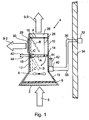
- the underside of the extractor hood 4 shown in Fig. 1, through which the air to be cleaned is sucked, may be partially or completely open and in the open area a bottom 2 in the form of a perforated plate or grid or other air-permeable plate-like element, above which Grease filter 6 is followed by a fan 8 for generating an air flow 9 is arranged.
- the housing 10 has a funnel-like lower portion 11 with the bottom 2 and above an upper portion 12. In the upper portion 12 is located above the fan 8, an odor filter 14 and a shutter 16.
- the odor filter 14 and the shutter 16 are of a drive device 18th , Preferably, an electric linear actuator, or alternatively an electric motor in a recirculation position "A", an exhaust air position “C” or an intermediate position “B” pivotally.
- the odor filter 14 is actuated directly by the drive device 18, which in turn actuates the closure flap 16 via a connecting means 26 (articulated rod).
- Umluft ein “A” are the grease filter 6 and the odor filter 14 in the airway of the entire air flow 9 of the blower 8 and thereby filter out fat and unwanted odors from the air stream 9 out.
- a sensor 32 on an exterior wall 34 of the building generates a signal via signal lines 36, 38 in a control device 40 as a function of the outside temperature.
- the control device 40 controls the drive device 18 in dependence on the outside temperature, to which it is connected via electrical lines 42, 44 is.
- the flap 16 and the odor filter 14 are in the recirculation position "A", whereby the air flow 9 again completely supplied to the kitchen and thus does not have to be replaced by cold outside air. This avoids re-heating of the kitchen due to heat losses through the extractor hood 4.
- a certain second temperature which is preferably at or above a usual housing temperature (eg 18 ° C or higher)
- the flap 16 and the odor filter 14 are brought into exhaust air position "C" by the drive device.
- the flapper 16 and the odor filter 14 are in the intermediate position "B".
- an embodiment is possible in which no intermediate position "B" is provided.
- the first temperature and the second temperature may be identical or different.
- the adjustment of the flap 16 and the odor filter 14 can be carried out gradually or continuously continuously.
- a temperature range is provided as the first and / or the second temperature, the switching to one of the operating modes (circulating air position, intermediate position, exhaust position) with increasing temperature at the upper temperature range end and with decreasing temperature respectively at the lower temperature range end.
- the odor filter 14 is disposed directly in the recirculating air channel 29, preferably between the housing 10 and Um Kunststoffgitter 30, whereby a switching of the odor filter 14 between the recirculation position "A" and the exhaust air position "C" is omitted.
- the fan 8 is arranged downstream of the odor filter 14 in the flow direction.
- the invention also makes it possible to provide additional means by which the outside temperature control can be switched off and a switchover between recirculation mode and exhaust air operation manually and / or via a switch, button or similar by the electric motor 18 is possible without the hood needs to be disassembled and without tools are required.
Landscapes
- Engineering & Computer Science (AREA)
- Ventilation (AREA)
- Chemical & Material Sciences (AREA)
- Combustion & Propulsion (AREA)
- Mechanical Engineering (AREA)
- General Engineering & Computer Science (AREA)
- Superstructure Of Vehicle (AREA)
Description
- Die Erfindung betrifft eine Dunstabzugshaube gemäß dem Oberbegriff von Anspruch 1.
- Demgemäß betrifft die Erfindung eine Dunstabzugshaube, welche eine Umschaltvorrichtung zum Umschalten zwischen Abluftbetrieb und Umluftbetrieb aufweist.
- Aus DE 30 40 051 A ist eine gattungsgemäße Dunstabzugshaube bekannt, die mit einer Steuervorrichtung ausgebildet ist, bei der in einem Gesamtluftweg eine Aufteilung des Gesamtluftstromes in einen Abluft- und einem Umluftstrom vorgenommen wird.
- Aus der DE-B-23 63 820 ist eine Dunstabzugshaube bekannt, welche eine Geruchsfilterkassette innerhalb des Gehäuses der Dunstabzugshaube aufweist, in welcher sich auch ein Fettfilter und ein Gebläse befinden. Das Filtermaterial des Geruchsfilters kann Aktivkohle oder ein anderes Material sein, welches durch Adhäsion, Adsorption, Absorption oder auf anderem chemischen Wege Gerüche aus dem Luftstrom herausfiltert, welcher von dem Gebläse erzeugt wird und zuerst durch den Fettfilter und dann durch den Geruchsfilter hindurchströmt. Das Gebläse kann im Strömungsweg zwischen dem Fettfilter und dem Geruchsfilter angeordnet sein, wie dies diese Schrift und auch das DE-Gebrauchsmuster G 91 05 430.3 zeigen. Gemäß der DE-A-27 14 286 und dem DE-Gebrauchsmuster 1 987 333 ist es auch möglich, das Gebläse stromabwärts des Geruchsfilters anzuordnen. Ferner ist es aus dem DE-Gebrauchsmuster GM 78 02 041 bekannt, in einer Dunstabzugshaube mehrere, beispielsweise zwei Gebläse zu verwenden. Aus dieser Schrift sind weiterhin Klappen bekannt, die eine Umstellung zwischen einem Umluftbetrieb, bei dem der Luftstrom in den Raum, in dem sich die Dunstabzugshaube befindet, beispielsweise eine Küche, zurückgerichtet ist, und einem Abluftbetrieb, bei dem der Luftstrom aus dem genannten Raum heraus in einen Außenbereich gerichtet ist, ermöglichen.
- Bei Abluftbetrieb muß die aus der Küche entfernte Luft ersetzt werden, insbesondere durch Außenluft. Diese muß in der kalten Jahreszeit auf Zimmertemperatur aufgeheizt werden, wodurch sich ein hoher Wärmeverlust oder, bei hoher Luftförderleistung des Gebläses, eine starke Abkühlung der Küche ergibt. Ein ständiger Umluftbetrieb führt dagegen zu einer raschen Verschmutzung des Geruchsfilters.
- Durch die Erfindung soll die Aufgabe gelöst werden, die genannten Nachteile zu vermeiden, insbesondere die Dunstabzugshaube bei tiefen Außentemperaturen automatisch im Umluftbetrieb und bei hohen Außentemperaturen automatisch im Abluftbetrieb zu betreiben.
- Diese Aufgabe wird gemäß der Erfindung durch die kennzeichnenden Merkmale von Anspruch 1 gelöst.
- Weitere Merkmale von Weiterbildungen der Erfindung sind in den Unteransprüchen enthalten.
- Gemäß der Erfindung sind eine Umschaltvorrichtung zum Umschalten zwischen Umluftbetrieb und Abluftbetrieb, eine elektrische Antriebsvorrichtung und eine elektrische Steuervorrichtung vorgesehen, durch welche die Umschaltvorrichtung von der Antriebsvorrichtung in Abhängigkeit von Außentemperaturen automatisch zwischen Abluftbetrieb und Umluftbetrieb umschaltbar ist, wobei unterhalb einer vorbestimmten ersten Temperatur auf Umluftbetrieb und oberhalb einer bestimmten zweiten Temperatur auf Abluftbetrieb automatisch umschaltbar ist.
- Aufgrund des automatischen Umschaltens von Abluftbetrieb auf Umluftbetrieb und umgekehrt, in Abhängigkeit von der Außentemperatur, wird ein energiesparender Betrieb der Dunstabzugshaube auch in der kalten Jahreszeit gewährleistet. Die Außentemperatur kann beispielsweise mit einem Außentemperaturfühler gemessen werden, welcher ein die Außentemperatur repräsentierendes Signal an die Steuervorrichtung abgibt, die dem Signal entsprechend die Antriebsvorrichtung aktiviert.
- Gemäß der Erfindung kann vorgesehen sein, daß mit dem Umschalten von Umluft auf Abluftbetrieb der Luftstrom an dem Geruchsfilter vorbeigeleitet wird oder der Geruchsfilter aus dem Luftweg entfernt wird. Dadurch wird eine Verzögerung der Verschmutzung des Geruchsfilters erreicht. Zusätzlich ergibt sich je nach konstruktiver Ausgestaltung eine erhöhte Saugleistung der Dunstabzugshaube, da der Strömungswiderstand für die Luftströmung durch das Umgehen des Geruchsfilters verringert wird. Der Geruchsfilter kann insbesondere ein Aktivkohlefilter oder ein anderes Material sein, welches durch Adhäsion, Adsorption, Absorption oder auf anderem chemischen Wege Gerüche aus dem Luftstrom herausfiltert.
- Die erste und die zweite Temperatur liegen um einen vorbestimmten Temperaturbereich auseinander. Es kann vorgesehen sein, daß die Umschaltvorrichtung auf eine Zwischenstellung für einen Betrieb mit einem Anteil Abluft und gleichzeitig mit einem Anteil Umluft schaltbar ist, wobei die Umschaltvorrichtung durch die elektrische Antriebsvorrichtung temperaturgesteuert automatisch in die Zwischenschaltung schaltbar ist, wenn die Außentemperatur innerhalb eines vorbestimmten Temperaturbereiches liegt.
Für den Betrieb der Dunstabzugshaube in diesem Temperaturzwischenbereich kann vorgesehen sein, daß ein Geruchsfilter vollständig außerhalb des Dunstabzugs-Gesamt-Luftstromes liegt oder nur in dem Umluftstromteil oder sowohl im Umluftstromteil als auch im Abluftstromteil liegt. - Die Erfindung wird im folgenden mit Bezug auf die Zeichnung anhand einer bevorzugten Ausführungsform als Beispiel beschrieben. In der Zeichnung zeigt
- Fig. 1
- eine Dunstabzugshaube gemäß der Erfindung im Vertikalschnitt.
- Die Unterseite der in Fig. 1 dargestellten Dunstabzugshaube 4, durch welche die zu reinigende Luft angesaugt wird, kann teilweise oder vollkommen offen sein und im offenen Bereich einen Boden 2 in Form eines Lochbleches oder Gitters oder eines anderen luftdurchlässigen plattenartigen Elementes haben, über welchem ein Fettfilter 6 gefolgt von einem Gebläse 8 zur Erzeugung eines Luftstromes 9 angeordnet ist. Das Gehäuse 10 hat einen trichterartigen unteren Abschnitt 11 mit dem Boden 2 und darüber einen oberen Abschnitt 12. Im oberen Abschnitt 12 befindet sich oberhalb des Gebläses 8 ein Geruchsfilter 14 und eine Verschlußklappe 16. Der Geruchsfilter 14 und die Verschlußklappe 16 sind von einer Antriebsvorrichtung 18, vorzugsweise ein elektrischer Linear-Stellantrieb, oder alternativ ein Elektromotor, in eine Umluftstellung "A", eine Abluftstellung "C" oder eine Zwischenstellung "B" schwenkbar. Der Geruchsfilter 14 wird direkt durch die Antriebsvorrichtung 18 betätigt, welche ihrerseits über ein Verbindungsmittel 26 (Gelenkstange) die Verschlußklappe 16 betätigt. In Umluftstellung "A" befinden sich der Fettfilter 6 und der Geruchsfilter 14 im Luftweg des gesamten Luftstromes 9 des Gebläses 8 und filtern dadurch Fett und unerwünschte Gerüche aus dem Luftstrom 9 heraus. Gleichzeitig verschließt die Verschlußklappe 16 in Umluftstellung "A" einen Abluftkanal 28 im oberen Gehäuseabschnitt 12 und leitet den vom Fettfilter 6 gefilterten und vom Geruchsfilter 14 geruchsneutralisierten Luftstrom 9-2 durch einen Umluftkanal 29, der ein Umluftgitter 30 enthalten kann, in den Raum bzw. in die Küche, in der die Dunstabzugshaube 4 installiert ist, zurück.
- In der Abluftstellung "C" ist der Geruchsfilter 14 aus dem Luftweg herausgeschwenkt, wodurch eine Verunreinigung dieses Geruchsfilters im Abluftbetrieb vermieden wird. Durch das Verbindungsmittel 26 wurde auch die Verschlußklappe 16 in Abluftstellung "C" gebracht, in welcher die Verschlußklappe den Abluftkanal 28 freigibt und gleichzeitig den Umluftkanal 29 verschließt. Der vom Fettfilter 6 gefilterte Luftstrom 9-3 wird durch den Abluftkanal 28 und danach durch eine Gebäudewand aus der Küche heraus in das Freie geleitet.
- In Zwischenstellung "B" strömt nur ein Teil des Luftstromes 9 durch den Geruchsfilter 14 und durch den Umluftkanal 29 in die Küche zurück, während ein anderer Teil an dem Geruchsfilter 14 vorbei und durch den Abluftkanal 28 ins Freie strömt. Die Strömungsaufteilung erfolgt an dem Geruchsfilter 14 und an der Verschlußklappe 16 durch deren Schrägstellung.
- Ein Sensor 32 an einer Außenwand 34 des Gebäudes erzeugt in Abhängigkeit von der Außentemperatur ein Signal über Signalleitungen 36,38 in einer Steuervorrichtung 40. Die Steuervorrichtung 40 steuert in Abhängigkeit von der Außentemperatur die Antriebsvorrichtung 18, mit der sie über elektrische Leitungen 42,44 verbunden ist.
- Gemäß der Erfindung ist vorgesehen, daß sich bei tiefen Außentemperaturen, die unter einer vorbestimmten ersten Temperatur (z. B. 10° C oder niedriger) liegen, die Verschlußklappe 16 und der Geruchsfilter 14 in Umluftstellung "A" befinden, wodurch der Luftstrom 9 wieder vollständig der Küche zugeführt wird und somit nicht durch kalte Außenluft ersetzt werden muß. Dadurch wird ein Nachheizen der Küche aufgrund von Wärmeverlusten durch die Dunstabzugshaube 4 vermieden. Bei Außentemperaturen oberhalb einer bestimmten zweiten Temperatur, die vorzugsweise bei oder oberhalb einer üblichen Wohnraumtemperatur (z. B. 18° C oder höher) liegt, wird die Verschlußklappe 16 und der Geruchsfilter 14 von der Antriebsvorrichtung in Abluftstellung "C" gebracht. Dadurch wird eine unnötige Verschmutzung des Geruchsfilters 14 während des Abluftbetriebes vermieden und die zum Ersatz der Abluft in die Küche nachströmende frische Außenluft verursacht aufgrund ihrer relativ hohen Temperatur keine zusätzlichen Heizkosten.
- Bei Außentemperaturen, die zwischen der genannten ersten Temperatur und der genannten zweiten Temperatur liegen, ist ein Mischbetrieb möglich, bei welchem die Verschlußklappe 16 und der Geruchsfilter 14 in der Zwischenstellung "B" sind. Andererseits ist auch eine Ausführungsform möglich, bei welcher keine Zwischenstellung "B" vorgesehen ist. Hier können die erste Temperatur und die zweite Temperatur identisch oder verschieden sein.
- Je nach Ausbildung der Steuervorrichtung 40, der Antriebsvorrichtung 18 und des Sensors 32 kann die Verstellung der Verschlußklappe 16 und des Geruchsfilters 14 stufenweise oder stufenlos kontinuierlich erfolgen.
- Gemäß der Erfindung ist als erste und/oder als zweite Temperatur jeweils ein Temperaturbereich vorgesehen, wobei die Umschaltung in eine der Betriebsarten (Umluftstellung, Zwischenstellung, Abluftstellung) bei steigender Temperatur jeweils am oberen Temperaturbereichsende und bei sinkender Temperatur jeweils am unteren Temperaturbereichsende erfolgt. Dadurch wird vermieden, daß bereits bei kleinen Temperaturschwankungen, beispielsweise durch kurzfristige Abschattung des Temperatursensors 32 durch Wolken, oder durch Schwankungen im Temperatursignal selbst, ein ständiges Hinund Herschalten zwischen den oben genannten Betriebsarten stattfindet.
- Bei einer weiteren Ausführungsform ist vorgesehen, daß der Geruchsfilter 14 direkt in dem Umluftkanal 29, vorzugsweise zwischen Gehäuse 10 und Umluftgitter 30 angeordnet ist, wodurch ein Umschalten des Geruchsfilters 14 zwischen der Umluftstellung "A" und der Abluftstellung "C" entfällt.
- Bei einer weiteren Ausführungsform ist vorgesehen, daß das Gebläse 8 in Strömungsrichtung nach dem Geruchsfilter 14 angeordnet ist.
- Anstatt einer Verschlußklappe 16 kann eine Strömungsweiche oder eine andere Strömungsumleitvorrichtung verwendet werden.
- Die Erfindung ermöglicht es auch, zusätzliche Mittel vorzusehen, durch welche die Außentemperaturregelung abschaltbar ist und eine Umschaltung zwischen Umluftbetrieb und Abluftbetrieb manuell und/oder über einen Schalter, Taster oder ähnlichem durch den Elektromotor 18 möglich ist, ohne daß die Dunstabzugshaube demontiert zu werden braucht und ohne daß Werkzeuge erforderlich sind.
Claims (5)
- Dunstabzugshaube (4), welche eine Umschaltvorrichtung (16) zum Umschalten zwischen Abluftbetrieb und Umluftbetrieb aufweist, wobei eine elektrische Antriebsvorrichtung (18) und eine elektrische Steuervorrichtung (40) vorgesehen sind, durch welche die Umschaltvorrichtung (16) von der Antriebsvorrichtung (18) in Abhängigkeit von Außentemperaturen (32) automatisch zwischen Abluftbetrieb (C) und Umluftbetrieb (A) umschaltbar ist, wobei unterhalb einer vorbestimmten ersten Außentemperatur auf Umluftbetrieb (A) und oberhalb einer bestimmten zweiten Außentemperatur auf Abluftbetrieb (C) automatisch umschaltbar ist, dadurch gekennzeichnet, daß als erste Außentemperatur und/oder als zweite Außentemperatur jeweils ein Temperaturbereich vorgesehen ist und daß die Umschaltung auf eine der genannten Betriebsarten (A, C) bei steigender Außentemperatur jeweils am oberen Temperaturbereichsende und bei fallender Außentemperatur jeweils am unteren Temperaturbereichsende erfolgt.
- Dunstabzugshaube nach Anspruch 1, dadurch gekennzeichnet, daß die erste Außentemperatur und die zweite Außentemperatur um einen vorbestimmten Temperaturbereich auseinanderliegen, daß die Umschaltvorrichtung (16) auf eine Zwischenstellung (B) für einen Betrieb mit einem Anteil Abluft und gleichzeitig mit einem Anteil Umluft schaltbar ist, und daß die Umschaltvorrichtung (16) durch die elektrische Antriebsvorrichtung (18) temperaturgesteuert durch die Steuervorrichtung (40) automatisch in die Zwischenstellung (B) schaltbar ist, wenn die Außentemperatur (32) innerhalb des vorbestimmten Temperaturbereiches liegt.
- Dunstabzugshaube nach Anspruch 1 oder 2, dadurch gekennzeichnet, daß an die Steuerschaltung (40) ein Außentemperaturfühler (32) angeschlossen ist.
- Dunstabzugshaube nach einem der vorhergehenden Ansprüche, dadurch gekennzeichnet, daß ein Geruchsfilter (14) zum Entziehen von Düften aus der Luft vorgesehen ist, welcher mit der Antriebsvorrichtung (18) antriebsmäßig verbunden (26) und von ihr automatisch für Abluftbetrieb (C) in und für Umluftbetrieb (A) aus dem Luftströmungsweg bewegbar ist.
- Dunstabzugshaube nach Anspruch 4, dadurch gekennzeichnet, daß der Geruchsfilter (14) ein Aktivkohlefilter ist.
Applications Claiming Priority (2)
| Application Number | Priority Date | Filing Date | Title |
|---|---|---|---|
| DE19923993 | 1999-05-26 | ||
| DE19923993A DE19923993A1 (de) | 1999-05-26 | 1999-05-26 | Dunstabzugshaube |
Publications (3)
| Publication Number | Publication Date |
|---|---|
| EP1055883A2 EP1055883A2 (de) | 2000-11-29 |
| EP1055883A3 EP1055883A3 (de) | 2003-07-30 |
| EP1055883B1 true EP1055883B1 (de) | 2006-12-20 |
Family
ID=7909165
Family Applications (1)
| Application Number | Title | Priority Date | Filing Date |
|---|---|---|---|
| EP00111278A Expired - Lifetime EP1055883B1 (de) | 1999-05-26 | 2000-05-25 | Dunstabzugshaube |
Country Status (4)
| Country | Link |
|---|---|
| EP (1) | EP1055883B1 (de) |
| AT (1) | ATE348984T1 (de) |
| DE (2) | DE19923993A1 (de) |
| ES (1) | ES2276649T3 (de) |
Cited By (5)
| Publication number | Priority date | Publication date | Assignee | Title |
|---|---|---|---|---|
| DE102007053819A1 (de) | 2007-11-12 | 2009-05-14 | BSH Bosch und Siemens Hausgeräte GmbH | Dunstabzugsvorrichtung |
| EP2476960A1 (de) | 2011-01-12 | 2012-07-18 | Naber Holding GmbH & Co. KG | Umschaltvorrichtung für eine Dunstabzugshaube zum Umschalten zwischen Umluft- und Abluftbetrieb |
| CN101443595B (zh) * | 2006-02-21 | 2012-10-10 | 苏剑蕾 | 通风、排气管道以及风扇的控制装置 |
| DE102015116863A1 (de) | 2015-10-05 | 2017-04-06 | Miele & Cie. Kg | Im Abluft- und Umluftbetrieb zu betreibende Dunstabzugshaube |
| EP3667176A1 (de) | 2018-12-11 | 2020-06-17 | Franke Futurum AB | Dunstabzugshaube, verfahren zum betreiben einer rauchabzugshaube |
Families Citing this family (8)
| Publication number | Priority date | Publication date | Assignee | Title |
|---|---|---|---|---|
| EP1363718A2 (de) | 2001-03-01 | 2003-11-26 | Phillips Plastics Corporation | Filtermedien aus porösen anorganischen partikeln |
| US7041159B2 (en) | 2003-08-04 | 2006-05-09 | Phillips Plastics Corporation | Separation apparatus |
| DE10247194A1 (de) * | 2002-10-10 | 2004-04-22 | BSH Bosch und Siemens Hausgeräte GmbH | Dunstabzugseinrichtung und Verfahren zum Reinigen von Luft |
| US7166140B2 (en) | 2003-10-22 | 2007-01-23 | Phillips Plastics Corporation | High capture efficiency baffle |
| DE102006024658A1 (de) * | 2006-05-22 | 2007-11-29 | Werner Pauen | Einrichtung für Dunstabzugshauben zum Wechselbetrieb zwischen Umluft und abluft, abhängig von der Außentemperatur |
| CH701800B1 (de) | 2009-09-01 | 2015-02-13 | Wesco Ag | Einrichtung zum Umleiten eines Luftstroms für eine Dunstabzugshaube. |
| EP2789921B1 (de) * | 2013-04-09 | 2017-04-05 | Silverline Küchengeräte und Handel GmbH | Dunstabzugshaube |
| CN106949515A (zh) * | 2017-04-19 | 2017-07-14 | 河海大学 | 一种联合无动力通风机的公共烟道油烟净化回收装置 |
Family Cites Families (10)
| Publication number | Priority date | Publication date | Assignee | Title |
|---|---|---|---|---|
| DE1987333U (de) | 1968-06-12 | Collo Rheincollodium Köln G.m.b.H. Werk Hersei, 5304 Hersei | Dunstabzugshaube | |
| DE2363820C3 (de) | 1973-12-21 | 1980-02-21 | Licentia-Patent-Verwaltungs-Gmbh, 6000 Frankfurt | Küchendunstfiltervorrichtung |
| DE2714286A1 (de) | 1977-03-31 | 1978-10-12 | Bosch Siemens Hausgeraete | Plattenfoermiges filter, insbesondere geruchsfilter fuer kuechen-dunstabzugshauben o.dgl. |
| DE7802041U1 (de) | 1978-01-24 | 1978-05-03 | G. Bauknecht Gmbh, Elektrotechnische Fabriken, 7000 Stuttgart | Dunstabzugshaube |
| DE3040051A1 (de) * | 1980-10-23 | 1982-06-03 | Georg Röhl, Lichttechnische Spezialfabrik, Apparate- und Gerätebau GmbH & Co KG, 8400 Regensburg | Steuervorrichtung fuer abluft-umluft-foerdergeraete und -systeme, insbesondere fuer dunstabzugshauben |
| DE3404004A1 (de) * | 1983-04-19 | 1984-10-25 | Friedrich 8000 München Bürcher | Ab- und zuluftvorrichtung fuer eine kochstelle |
| DE3603028A1 (de) * | 1986-01-31 | 1987-08-06 | Buercher Siegrist Rosmarie | Kuechenentlueftungsanlage |
| DE3625975C2 (de) * | 1986-07-31 | 1997-07-10 | Lubbe Karlheinz Dipl Ing | Umschaltvorrichtung für den wahlweisen Umluft- oder Abluftbetrieb einer Dunstabzugshaube |
| DE9105430U1 (de) | 1991-05-02 | 1992-09-03 | Bosch-Siemens Hausgeräte GmbH, 8000 München | Dunstabzugseinrichtung |
| DE9208718U1 (de) * | 1992-06-30 | 1992-09-17 | Bürcher, Friedrich, 8029 Sauerlach | Bauelement einer Lüftungsinstallation |
-
1999
- 1999-05-26 DE DE19923993A patent/DE19923993A1/de not_active Ceased
-
2000
- 2000-05-25 ES ES00111278T patent/ES2276649T3/es not_active Expired - Lifetime
- 2000-05-25 AT AT00111278T patent/ATE348984T1/de not_active IP Right Cessation
- 2000-05-25 EP EP00111278A patent/EP1055883B1/de not_active Expired - Lifetime
- 2000-05-25 DE DE50013876T patent/DE50013876D1/de not_active Expired - Lifetime
Cited By (7)
| Publication number | Priority date | Publication date | Assignee | Title |
|---|---|---|---|---|
| CN101443595B (zh) * | 2006-02-21 | 2012-10-10 | 苏剑蕾 | 通风、排气管道以及风扇的控制装置 |
| DE102007053819A1 (de) | 2007-11-12 | 2009-05-14 | BSH Bosch und Siemens Hausgeräte GmbH | Dunstabzugsvorrichtung |
| WO2009062809A2 (de) | 2007-11-12 | 2009-05-22 | BSH Bosch und Siemens Hausgeräte GmbH | Dunstabzugsvorrichtung |
| EP2476960A1 (de) | 2011-01-12 | 2012-07-18 | Naber Holding GmbH & Co. KG | Umschaltvorrichtung für eine Dunstabzugshaube zum Umschalten zwischen Umluft- und Abluftbetrieb |
| DE102015116863A1 (de) | 2015-10-05 | 2017-04-06 | Miele & Cie. Kg | Im Abluft- und Umluftbetrieb zu betreibende Dunstabzugshaube |
| DE102015116863B4 (de) * | 2015-10-05 | 2025-10-23 | Miele & Cie. Kg | Im Abluft- und Umluftbetrieb zu betreibende Dunstabzugshaube |
| EP3667176A1 (de) | 2018-12-11 | 2020-06-17 | Franke Futurum AB | Dunstabzugshaube, verfahren zum betreiben einer rauchabzugshaube |
Also Published As
| Publication number | Publication date |
|---|---|
| ES2276649T3 (es) | 2007-07-01 |
| EP1055883A3 (de) | 2003-07-30 |
| DE50013876D1 (de) | 2007-02-01 |
| DE19923993A1 (de) | 2000-11-30 |
| ATE348984T1 (de) | 2007-01-15 |
| EP1055883A2 (de) | 2000-11-29 |
Similar Documents
| Publication | Publication Date | Title |
|---|---|---|
| EP1055883B1 (de) | Dunstabzugshaube | |
| DE69625027T2 (de) | Anlage mit Filterzustandsensor und -anzeiger | |
| EP2570735B1 (de) | Dunstabzugssystem und Verfahren zum Betreiben eines Dunstabzugssystems | |
| DE19654955C2 (de) | Klimatisierungsvorrichtung | |
| DE2149548B2 (de) | Klimaanlage für Eisenbahnfahrzeuge | |
| EP2880368B1 (de) | Dunstabzugsvorrichtung und verfahren zum ansteuerung eines lüftermotors eines lüfters | |
| EP1278993A1 (de) | Dunstabzugshaube | |
| DE3040051A1 (de) | Steuervorrichtung fuer abluft-umluft-foerdergeraete und -systeme, insbesondere fuer dunstabzugshauben | |
| DE19711031A1 (de) | Heizungs-, Lüftungs- und/oder Klimaanlage mit Leistungsregelung, insbesondere für Kraftfahrzeuge | |
| DE19509495C1 (de) | Verfahren zur Steuerung der Belüftung eines Fahrzeuginnenraumes | |
| DE3603028A1 (de) | Kuechenentlueftungsanlage | |
| EP3772620B1 (de) | Luftbehandlungssystem zur verbesserung einer luftqualität einer innenluft in einem raum und verfahren zu dessen betrieb | |
| DE102014015231A1 (de) | Klimatisierungsvorrichtung für einen abgeschlossenen Raum und Betriebsverfahren für eine Klimatisierungsvorrichtung | |
| DE102020124068A1 (de) | Downdraftlüfter und Verfahren zum Betreiben | |
| EP0857593B1 (de) | Klimaanlage für den Innenraum eines Fahrzeuges | |
| DE10316294A1 (de) | Verfahren zur Steuerung/Regelung einer klimaanlage für ein Kraftfahrzeug | |
| DE102015116863B4 (de) | Im Abluft- und Umluftbetrieb zu betreibende Dunstabzugshaube | |
| EP1475260A1 (de) | Heizsystem für ein Fahrzeug | |
| DE102021110574B4 (de) | System, umfassend ein Gargerät mit einem Garraum und eine Dunstabzugsvorrichtung, und Verfahren zum Betrieb eines Systems | |
| EP2645009B1 (de) | Lüftungsanlage | |
| DE60101825T2 (de) | Motorisierte Abzugshaube für Küchen | |
| DE2423188A1 (de) | Regelsystem fuer fahrzeugklimaanlage | |
| DE3007407A1 (de) | Heizungs-, belueftungs- oder klimaanlage fuer kraftfahrzeuge | |
| DE8805325U1 (de) | Dunstabzugshaube | |
| DE102023103673B4 (de) | Dunstabzugseinheit und Verfahren zum Betrieb einer Dunstabzugseinheit |
Legal Events
| Date | Code | Title | Description |
|---|---|---|---|
| PUAI | Public reference made under article 153(3) epc to a published international application that has entered the european phase |
Free format text: ORIGINAL CODE: 0009012 |
|
| AK | Designated contracting states |
Kind code of ref document: A2 Designated state(s): AT BE CH CY DE DK ES FI FR GB GR IE IT LI LU MC NL PT SE |
|
| AX | Request for extension of the european patent |
Free format text: AL;LT;LV;MK;RO;SI |
|
| PUAL | Search report despatched |
Free format text: ORIGINAL CODE: 0009013 |
|
| AK | Designated contracting states |
Designated state(s): AT BE CH CY DE DK ES FI FR GB GR IE IT LI LU MC NL PT SE |
|
| AX | Request for extension of the european patent |
Extension state: AL LT LV MK RO SI |
|
| RAP1 | Party data changed (applicant data changed or rights of an application transferred) |
Owner name: BSH BOSCH UND SIEMENS HAUSGERAETE GMBH |
|
| 17P | Request for examination filed |
Effective date: 20040130 |
|
| AKX | Designation fees paid |
Designated state(s): AT BE CH CY DE DK ES FI FR GB GR IE IT LI LU MC NL PT SE |
|
| 17Q | First examination report despatched |
Effective date: 20050309 |
|
| GRAP | Despatch of communication of intention to grant a patent |
Free format text: ORIGINAL CODE: EPIDOSNIGR1 |
|
| GRAS | Grant fee paid |
Free format text: ORIGINAL CODE: EPIDOSNIGR3 |
|
| GRAA | (expected) grant |
Free format text: ORIGINAL CODE: 0009210 |
|
| AK | Designated contracting states |
Kind code of ref document: B1 Designated state(s): AT BE CH CY DE DK ES FI FR GB GR IE IT LI LU MC NL PT SE |
|
| PG25 | Lapsed in a contracting state [announced via postgrant information from national office to epo] |
Ref country code: NL Free format text: LAPSE BECAUSE OF FAILURE TO SUBMIT A TRANSLATION OF THE DESCRIPTION OR TO PAY THE FEE WITHIN THE PRESCRIBED TIME-LIMIT Effective date: 20061220 Ref country code: IE Free format text: LAPSE BECAUSE OF FAILURE TO SUBMIT A TRANSLATION OF THE DESCRIPTION OR TO PAY THE FEE WITHIN THE PRESCRIBED TIME-LIMIT Effective date: 20061220 Ref country code: FI Free format text: LAPSE BECAUSE OF FAILURE TO SUBMIT A TRANSLATION OF THE DESCRIPTION OR TO PAY THE FEE WITHIN THE PRESCRIBED TIME-LIMIT Effective date: 20061220 Ref country code: DK Free format text: LAPSE BECAUSE OF FAILURE TO SUBMIT A TRANSLATION OF THE DESCRIPTION OR TO PAY THE FEE WITHIN THE PRESCRIBED TIME-LIMIT Effective date: 20061220 |
|
| REG | Reference to a national code |
Ref country code: GB Ref legal event code: FG4D Free format text: NOT ENGLISH |
|
| REG | Reference to a national code |
Ref country code: CH Ref legal event code: EP |
|
| REF | Corresponds to: |
Ref document number: 50013876 Country of ref document: DE Date of ref document: 20070201 Kind code of ref document: P |
|
| GBT | Gb: translation of ep patent filed (gb section 77(6)(a)/1977) |
Effective date: 20070117 |
|
| REG | Reference to a national code |
Ref country code: IE Ref legal event code: FG4D Free format text: LANGUAGE OF EP DOCUMENT: GERMAN |
|
| PG25 | Lapsed in a contracting state [announced via postgrant information from national office to epo] |
Ref country code: SE Free format text: LAPSE BECAUSE OF FAILURE TO SUBMIT A TRANSLATION OF THE DESCRIPTION OR TO PAY THE FEE WITHIN THE PRESCRIBED TIME-LIMIT Effective date: 20070320 |
|
| PG25 | Lapsed in a contracting state [announced via postgrant information from national office to epo] |
Ref country code: PT Free format text: LAPSE BECAUSE OF FAILURE TO SUBMIT A TRANSLATION OF THE DESCRIPTION OR TO PAY THE FEE WITHIN THE PRESCRIBED TIME-LIMIT Effective date: 20070423 |
|
| ET | Fr: translation filed | ||
| NLV1 | Nl: lapsed or annulled due to failure to fulfill the requirements of art. 29p and 29m of the patents act | ||
| REG | Reference to a national code |
Ref country code: ES Ref legal event code: FG2A Ref document number: 2276649 Country of ref document: ES Kind code of ref document: T3 |
|
| PLBE | No opposition filed within time limit |
Free format text: ORIGINAL CODE: 0009261 |
|
| STAA | Information on the status of an ep patent application or granted ep patent |
Free format text: STATUS: NO OPPOSITION FILED WITHIN TIME LIMIT |
|
| 26N | No opposition filed |
Effective date: 20070921 |
|
| BERE | Be: lapsed |
Owner name: BSH BOSCH UND SIEMENS HAUSGERATE G.M.B.H. Effective date: 20070531 |
|
| REG | Reference to a national code |
Ref country code: CH Ref legal event code: PL |
|
| PG25 | Lapsed in a contracting state [announced via postgrant information from national office to epo] |
Ref country code: MC Free format text: LAPSE BECAUSE OF NON-PAYMENT OF DUE FEES Effective date: 20070531 |
|
| PG25 | Lapsed in a contracting state [announced via postgrant information from national office to epo] |
Ref country code: CH Free format text: LAPSE BECAUSE OF NON-PAYMENT OF DUE FEES Effective date: 20070531 Ref country code: LI Free format text: LAPSE BECAUSE OF NON-PAYMENT OF DUE FEES Effective date: 20070531 |
|
| PG25 | Lapsed in a contracting state [announced via postgrant information from national office to epo] |
Ref country code: BE Free format text: LAPSE BECAUSE OF NON-PAYMENT OF DUE FEES Effective date: 20070531 |
|
| PG25 | Lapsed in a contracting state [announced via postgrant information from national office to epo] |
Ref country code: GR Free format text: LAPSE BECAUSE OF FAILURE TO SUBMIT A TRANSLATION OF THE DESCRIPTION OR TO PAY THE FEE WITHIN THE PRESCRIBED TIME-LIMIT Effective date: 20070321 |
|
| PG25 | Lapsed in a contracting state [announced via postgrant information from national office to epo] |
Ref country code: AT Free format text: LAPSE BECAUSE OF NON-PAYMENT OF DUE FEES Effective date: 20070525 |
|
| PG25 | Lapsed in a contracting state [announced via postgrant information from national office to epo] |
Ref country code: LU Free format text: LAPSE BECAUSE OF NON-PAYMENT OF DUE FEES Effective date: 20070525 Ref country code: CY Free format text: LAPSE BECAUSE OF FAILURE TO SUBMIT A TRANSLATION OF THE DESCRIPTION OR TO PAY THE FEE WITHIN THE PRESCRIBED TIME-LIMIT Effective date: 20061220 |
|
| PGFP | Annual fee paid to national office [announced via postgrant information from national office to epo] |
Ref country code: GB Payment date: 20110523 Year of fee payment: 12 |
|
| GBPC | Gb: european patent ceased through non-payment of renewal fee |
Effective date: 20120525 |
|
| PG25 | Lapsed in a contracting state [announced via postgrant information from national office to epo] |
Ref country code: GB Free format text: LAPSE BECAUSE OF NON-PAYMENT OF DUE FEES Effective date: 20120525 |
|
| REG | Reference to a national code |
Ref country code: DE Ref legal event code: R081 Ref document number: 50013876 Country of ref document: DE Owner name: BSH HAUSGERAETE GMBH, DE Free format text: FORMER OWNER: BSH BOSCH UND SIEMENS HAUSGERAETE GMBH, 81739 MUENCHEN, DE Effective date: 20150402 |
|
| REG | Reference to a national code |
Ref country code: FR Ref legal event code: PLFP Year of fee payment: 16 |
|
| REG | Reference to a national code |
Ref country code: ES Ref legal event code: PC2A Owner name: BSH HAUSGERATE GMBH Effective date: 20150527 |
|
| REG | Reference to a national code |
Ref country code: FR Ref legal event code: CD Owner name: BSH HAUSGERATE GMBH Effective date: 20151022 |
|
| REG | Reference to a national code |
Ref country code: FR Ref legal event code: PLFP Year of fee payment: 17 |
|
| REG | Reference to a national code |
Ref country code: FR Ref legal event code: PLFP Year of fee payment: 18 |
|
| REG | Reference to a national code |
Ref country code: FR Ref legal event code: PLFP Year of fee payment: 19 |
|
| PGFP | Annual fee paid to national office [announced via postgrant information from national office to epo] |
Ref country code: DE Payment date: 20180531 Year of fee payment: 19 Ref country code: ES Payment date: 20180626 Year of fee payment: 19 |
|
| REG | Reference to a national code |
Ref country code: DE Ref legal event code: R084 Ref document number: 50013876 Country of ref document: DE |
|
| PGFP | Annual fee paid to national office [announced via postgrant information from national office to epo] |
Ref country code: IT Payment date: 20190521 Year of fee payment: 20 |
|
| PGFP | Annual fee paid to national office [announced via postgrant information from national office to epo] |
Ref country code: FR Payment date: 20190521 Year of fee payment: 20 |
|
| REG | Reference to a national code |
Ref country code: DE Ref legal event code: R119 Ref document number: 50013876 Country of ref document: DE |
|
| PG25 | Lapsed in a contracting state [announced via postgrant information from national office to epo] |
Ref country code: DE Free format text: LAPSE BECAUSE OF NON-PAYMENT OF DUE FEES Effective date: 20191203 |
|
| REG | Reference to a national code |
Ref country code: ES Ref legal event code: FD2A Effective date: 20200928 |
|
| PG25 | Lapsed in a contracting state [announced via postgrant information from national office to epo] |
Ref country code: ES Free format text: LAPSE BECAUSE OF NON-PAYMENT OF DUE FEES Effective date: 20190526 |