EP1055896B1 - Ölkühler - Google Patents
Ölkühler Download PDFInfo
- Publication number
- EP1055896B1 EP1055896B1 EP00110582A EP00110582A EP1055896B1 EP 1055896 B1 EP1055896 B1 EP 1055896B1 EP 00110582 A EP00110582 A EP 00110582A EP 00110582 A EP00110582 A EP 00110582A EP 1055896 B1 EP1055896 B1 EP 1055896B1
- Authority
- EP
- European Patent Office
- Prior art keywords
- oil cooler
- border
- oil
- seal
- cooler according
- Prior art date
- Legal status (The legal status is an assumption and is not a legal conclusion. Google has not performed a legal analysis and makes no representation as to the accuracy of the status listed.)
- Expired - Lifetime
Links
- 239000002826 coolant Substances 0.000 claims abstract description 3
- 238000001746 injection moulding Methods 0.000 claims description 3
- 230000000694 effects Effects 0.000 claims description 2
- 238000007789 sealing Methods 0.000 abstract description 9
- 238000003780 insertion Methods 0.000 description 6
- 230000037431 insertion Effects 0.000 description 6
- 238000004519 manufacturing process Methods 0.000 description 5
- XLYOFNOQVPJJNP-UHFFFAOYSA-N water Substances O XLYOFNOQVPJJNP-UHFFFAOYSA-N 0.000 description 4
- 230000015572 biosynthetic process Effects 0.000 description 2
- 230000002093 peripheral effect Effects 0.000 description 2
- 238000005476 soldering Methods 0.000 description 2
- XAGFODPZIPBFFR-UHFFFAOYSA-N aluminium Chemical compound [Al] XAGFODPZIPBFFR-UHFFFAOYSA-N 0.000 description 1
- 229910052782 aluminium Inorganic materials 0.000 description 1
- 230000005540 biological transmission Effects 0.000 description 1
- 238000010276 construction Methods 0.000 description 1
- 238000001816 cooling Methods 0.000 description 1
- 239000000498 cooling water Substances 0.000 description 1
- 230000007547 defect Effects 0.000 description 1
- 238000005516 engineering process Methods 0.000 description 1
- 238000002347 injection Methods 0.000 description 1
- 239000007924 injection Substances 0.000 description 1
- 238000012986 modification Methods 0.000 description 1
- 230000004048 modification Effects 0.000 description 1
- 210000001331 nose Anatomy 0.000 description 1
Images


Classifications
-
- F—MECHANICAL ENGINEERING; LIGHTING; HEATING; WEAPONS; BLASTING
- F16—ENGINEERING ELEMENTS AND UNITS; GENERAL MEASURES FOR PRODUCING AND MAINTAINING EFFECTIVE FUNCTIONING OF MACHINES OR INSTALLATIONS; THERMAL INSULATION IN GENERAL
- F16N—LUBRICATING
- F16N39/00—Arrangements for conditioning of lubricants in the lubricating system
- F16N39/02—Arrangements for conditioning of lubricants in the lubricating system by cooling
-
- F—MECHANICAL ENGINEERING; LIGHTING; HEATING; WEAPONS; BLASTING
- F28—HEAT EXCHANGE IN GENERAL
- F28D—HEAT-EXCHANGE APPARATUS, NOT PROVIDED FOR IN ANOTHER SUBCLASS, IN WHICH THE HEAT-EXCHANGE MEDIA DO NOT COME INTO DIRECT CONTACT
- F28D9/00—Heat-exchange apparatus having stationary plate-like or laminated conduit assemblies for both heat-exchange media, the media being in contact with different sides of a conduit wall
- F28D9/0012—Heat-exchange apparatus having stationary plate-like or laminated conduit assemblies for both heat-exchange media, the media being in contact with different sides of a conduit wall the apparatus having an annular form
Definitions
- the invention relates to an oil cooler which consists of a plate pack, with the alternating Flow channels are formed for the oil and for the coolant, wherein the plate package and the base plate or cover plate covering the plate package of at least one collecting space is broken through, in or at the mouth of plastic elements releasably secured are having a connecting part, as well as between the base or cover plate and a Aggregate whose oil is to be cooled, provided seal, which provides a sealing area around the Mouth of a collecting space forms or the several mouths of several collecting spaces includes.
- Such oil coolers are in multiple modification on the market and are successfully used, for example.
- the oil cooler described is similar to the oil cooler shown in DE 38 24 073 C2, although its elements have not been specified as consisting of plastic and connecting parts are not there. If the elements are to be made of plastic, their production by means of injection molding technology is suitable, as has also been shown and described in EP 751 364 B1.
- Strömungsumschetti for two plenums can be made in one piece by injection molding and use in the plenums in a single operation, which has significant manufacturing advantages because individual assembly errors can be limited.
- the object of the invention is to produce the described in the preamble Oil cooler by eliminating the need to separately insert the seals and thereby further simplify that additional benefits for the formation of the oil cooler itself should be achieved.
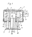
- the water-cooled oil cooler according to FIG. 1 has a housing 20 in which a nozzle 21 has been soldered in an opening. This can be the inlet connection for the cooling water.
- the outlet nozzle is in a different plane.
- the housing 20 is a plate pack 2, the structure of which can be taken from the prior art and therefore was not drawn in detail.
- the plate pack 2 has a base plate 3 and a cover plate 4. In this embodiment, the plate pack 2 and the base and cover plate 3; 4 of the Sammelräümen 5 and 12 broken.
- the collecting space 5 has an orifice 6 and the collecting space 12, the mouth 11. The water flows into the housing 20, between the plates of the plate pack 2 through and at another point, the water exits from the housing 20 again.
- the oil enters the collecting chamber 12, is within the channels formed by plates by means of the flow deflecting elements 16 formed elements 7 first to the periphery of the oil cooler, ie to the right, passed, as shown by the arrows and then flows to the left, to the plenum. 5 , from which it flows upwards into a filter not shown in order to get out of this, through the central channel 24, back into the below-arranged unit.
- elements 7 and the Strömungsumschetti 16 are releasably attached. In the drawing, these elements 7 are only partially in the plenums 5; 12 has been inserted to better emphasize the details.
- the central channel 24 is lined in this embodiment with a sleeve 22, which also consists of plastic and is part of the elements 7, but this does not necessarily have to be so.
- a sleeve 22 which also consists of plastic and is part of the elements 7, but this does not necessarily have to be so.
- the sleeve over its entire length range with a longitudinal gap 23 (see also Figs. 3 and 4) is provided.
- the longitudinal gap 23 is compressed and closed. The occurring radial tension keeps the plastic part in position.
- a seal 9 was glued, which comes after the insertion of the plastic part in the sealing region 10 on the base plate 3 to the plant. On the base plate 3 no positioning means for the seal 9 are required.
- Fig. 2 shows an oil cooler, which could belong to the housing-less design, ie in which both the channels for the oil and the channels for the water are formed and separated solely by the formation of the plates. Also on such an oil cooler a seal must be made to the aggregate, which is designed there so that a centering ring 17 has been provided with locking lugs 18.
- the locking lugs 18 engage in the mouth 6 of the collecting space 5 and thus also determine the position of the seal 9, which in turn was attached to the border 13.
- connecting elements 8 are arranged, which are designed as flat webs 19. 4 shows a view from below of the plastic part.
- the connecting part 8 has rather large openings 14. In the vicinity of the rim 13 further, but small, breakthroughs are provided, which serve to secure the seal 9, especially if this is to be vulcanized. From this illustration and also from FIG. 3, the shape of the Strömungsumschetti 16 can be detected, which is approximately half-round, wherein the semicircular contour is arranged in each case to the center of the oil cooler 1 back to reach the already mentioned flow of the periphery of the oil cooler.
- FIG. 5 shows a cross-sectionally round seal 9, which has been glued with its edge 15 on the border 13.
- 6 and 7 show another way of fastening the seal 9 to the border 13, in which the edge 15 has been formed U-shaped to accommodate the border 13 can. Such attachment can expect a higher strength.
- the seal 9 here has a wavy contour, which promises better sealing properties.
Landscapes
- Engineering & Computer Science (AREA)
- General Engineering & Computer Science (AREA)
- Mechanical Engineering (AREA)
- Physics & Mathematics (AREA)
- Thermal Sciences (AREA)
- Heat-Exchange Devices With Radiators And Conduit Assemblies (AREA)
- Packages (AREA)
- Lubrication Of Internal Combustion Engines (AREA)
- Sampling And Sample Adjustment (AREA)
- Fats And Perfumes (AREA)
- Lubrication Details And Ventilation Of Internal Combustion Engines (AREA)
Description
Der beschriebene Ölkühler ist dem in DE 38 24 073 C2 gezeigten Ölkühler ähnlich, obwohl dessen Elemente nicht als aus Kunststoff bestehend angegeben worden sind und Verbindungsteile dort nicht vorhanden sind. Sollen die Elemente aus Kunststoff hergestellt werden, bietet sich deren Herstellung mittels Spritzgußtechnik an, wie es auch im EP 751 364 B1 gezeigt und beschrieben worden ist. Insbesondere lassen sich Strömungsumlenkelemente für zwei Sammelräume aus einem Stück mittels Spritzgießen herstellen und in die Sammelräume in einer einzigen Operation einsetzen, was erhebliche fertigungstechnische Vorteile hat, weil individuelle Montagefehler eingeschränkt werden können.
Nichtsdestotrotz besteht weiterhin Bedarf, fertigungstechnische Fortschritte zu erreichen, beispielsweise im Bereich der Dichtungen, die ebenfalls von Hand einzulegen sind, wobei durch ungenaues Einlegen Fertigungsfehler auftreten können, die in der Folge zu Undichtigkeiten führen. Darüber hinaus kann das Einlegen der Dichtung völlig übersehen werden, was selbstverständlich zu Beanstandungen führen muß.
Ferner müssen zur Lagefixierung der Dichtung, die oft eine Ringdichtung ist, auf der Oberfläche der Grundplatte des Ölkühlers in Abständen Nasen oder dergleichen angeformt werden, was als nachteilig angesehen werden kann. Das gleiche muß natürlich auch an der Deckplatte vorgesehen werden, falls die Abdichtung zu einem darüber angeordneten Ölfilter gewünscht wird.
Zur Abdichtung von Sammelkästen aus Kunststoff mit dem zugehörigen Rohrboden, bspw. bei Wasserkühlern, ist es bekannt, die dafür erforderliche Dichtung unmittelbar an den Dichtrand des Sammelkastens anzuspritzen, damit das Einlegen der Dichtung entfallen kann. Deshalb scheint es naheliegend zu sein, bei anderen Wärmetauschern ebenfalls nach Möglichkeiten zum Entfall des Einlegens der Dichtung zu suchen. Jedoch scheiterten solche Überlegungen bei Ölkühlem bisher daran, daß dort Sammelkästen aus Kunststoff nicht zum Einsatz kommen. Gewöhnlich sind aus einem Plattenpaket bestehende Ölkühler komplett aus Aluminium hergestellt, wobei die Einzelteile durch Löten verbunden werden. Da bleibt kein Raum, um über das Anspritzen von Dichtungen nachzudenken, da solche Dichtungen selbstverständlich erst nach dem Löten angebracht werden können.
Durch die erfindungsgemäße Ausbildung kann die Deck-und/oder die Grundplatte, auf der die Dichtung mit dem Verbindungsteil aufliegt, einfacher hergestellt werden, ohne daß die Dichtwirkung eingeschränkt wird. Die im Stand der Technik vorgesehenen Nasen zur Lagepositionierung der Dichtung können entfallen. Nach der Erfindung erfolgt die Lagepositionierung der Dichtung in einem ersten Ausführungsbeispiel durch das Einführen der Elemente in den Sammelraum des Ölkühlers.
Die Elemente sind hier als Strömungsumlenkelemente ausgebildet, die das Öl innerhalb des Ölkühlers veranlassen, auch die äußeren Bereiche der Platten zu beströmen. Dadurch wird der Wärmeaustausch verbessert.
Bei einem anderen Ausführungsbeispiel sind die Elemente quasi als Zentrierring ausgebildet, der lediglich an der Mündung des Sammelraumes eingeclipst oder anderweitig lösbar befestigt ist.
Die erfindungsgemäßen Ölkühler lassen sich besser in eine automatisierte Fertigungslinie einordnen, weil das Einlegen und Positionieren der Dichtung an exakt der gleichen Stelle erfolgt und unabhängig von subjektiven Einflüssen ist.
Letztlich führt die Erfindung beim Kühlerhersteller zur Reduzierung der Anzahl der Einzelteile und damit zu logistischen Vorteilen. Die angesprochenen Elemente werden von spezialisierten Lieferanten hergestellt und komplett mit der Dichtung angeliefert.
Weitere Merkmale ergeben sich aus den Ansprüchen und aus der nachfolgenden Beschreibung von Ausführungsbeispielen.
Die beiliegenden Figuren zeigen:
- Fig. 1
- Querschnitt durch einen Ölkühler eines ersten Ausführungsbeispieles;
- Fig. 2
- perspektivische Ansicht eines Ölkühlers in einem zweiten Ausführungsbeispiel;
- Fig. 3
- Einzelteil des Ölkühlers aus Fig. 1;
- Fig. 4
- Ansicht von Fig. 3;
- Fig. 5
- Querschnitt durch das Umfangsteil von Fig. 4;
- Fig. 6
- Variante von Fig. 4
- Fig. 7
- Querschnitt durch das Umfangsteil von Fig. 6
Der zentrale Kanal 24 ist in diesem Ausführungsbeispiel mit einer Hülse 22 ausgekleidet, die ebenfalls aus Kunststoff besteht und Bestandteil der Elemente 7 ist, was jedoch nicht zwangsläufig so sein muß. Von Interesse ist jedoch, daß die Hülse über ihren gesamten Längenbereich mit einem Längsspalt 23 (siehe auch Fig. 3 und 4) versehen ist. Dadurch wurde eine hervorragende Möglichkeit geschaffen, unter Ausnutzung der elastischen Eigenschaften des Kunststoffes, die Hülse 22 und damit das gesamte Kunststoffteil zu befestigen. Beim Einschieben in den Kanal 24 wird der Längsspalt 23 zusammengedrückt und verschlossen. Die dabei auftretende radiale Spannung hält das Kunststoffteil in Position.
Nach unten, zu einem nicht gezeichneten Aggregat, dessen Öl zu kühlen ist, muß eine gute Abdichtung nach außen gewährleistet sein. Deshalb erstreckt sich das Verbindungsteil 8 der Elemente 7 bis zur Umrandung 13. An der Umrandung 13 wurde eine Dichtung 9 angeklebt, die nach dem Einführen des Kunststoffteiles im Abdichtungsbereich 10 an der Grundplatte 3 zur Anlage kommt.
An der Grundplatte 3 sind keinerlei Positionierungsmittel für die Dichtung 9 erforderlich.
Die Fig. 2 zeigt einen Ölkühler, der zur gehäuselosen Bauart gehören könnte, bei dem also sowohl die Kanäle für das Öl als auch die Kanäle für das Wasser allein durch die Ausbildung der Platten gebildet und getrennt sind. Auch an einem solchen Ölkühler muß eine Abdichtung zum Aggregat hin erfolgen, die dort so ausgeführt ist, daß ein Zentrierring 17 mit Rastnasen 18 versehen wurde.
Die Rastnasen 18 greifen in die Mündung 6 des Sammelraumes 5 ein und legen somit auch die Position der Dichtung 9 fest, die wiederum an der Umrandung 13 befestigt wurde. Zwischen dem Zentrierring 17 sind Verbindungselemente 8 angeordnet, die als flache Stege 19 ausgeführt sind.
Die Fig. 4 zeigt eine Ansicht von unten auf das Kunststoffteil. Das Verbindungsteil 8 besitzt ziemlich große Durchbrüche 14. In der Nähe der Umrandung 13 sind ringsherum weitere, jedoch kleine, Durchbrüche vorgesehen, die der Befestigung der Dichtung 9 dienen, insbesondere wenn diese aufvulkanisiert werden soll. Aus dieser Darstellung und auch aus Fig. 3 kann die Form der Strömungsumlenkelemente 16 erkannt werden, die etwa halbrund ist, wobei die halbrunde Kontur jeweils zum Zentrum des Ölkühlers 1 hin angeordnet ist, um die bereits angesprochene Beströmung der Peripherie des Ölkühlers zu erreichen.
Die Fig. 5 zeigt eine im Querschnitt runde Dichtung 9, die mit ihrem Rand 15 an der Umrandung 13 angeklebt worden ist.
Die Fig. 6 und 7 zeigen eine andere Art der Befestigung der Dichtung 9 an der Umrandung 13, bei der der Rand 15 u-förmig ausgebildet worden ist, um die Umrandung 13 aufnehmen zu können.
Eine solche Befestigung läßt eine höhere Festigkeit erwarten. Die Dichtung 9 hat hier eine wellenförmige Kontur, die bessere Dichtungseigenschaften verspricht.
Claims (9)
- Ölkühler (1) der aus einem Plattenpaket (2) besteht, mit dem sich abwechselnde Strömungskanäle für das Öl und für das Kühlmittel gebildet sind, wobei das Plattenpaket (2) und die das Plattenpaket (2) abdeckende Grund-oder Deckplatte (3:4) von mindestens einem Sammelraum (5) durchbrochen ist, in dem oder an dessen Mündung (6) Elemente (7) aus Kunststoff lösbar befestigt sind, die ein Verbindungsteil (8) aufweisen, sowie mit zwischen der Grund-oder Deckplatte und einem Aggregat, dessen Öl zu kühlen ist, vorgesehener Dichtung (9), die einen Abdichtungsbereich (10) um die Mündung (6) eines Sammelraumes (5) bildet oder die mehrere Mündungen (6;11) von mehreren Sammelräumen (5:12) umfaßt,
dadurch gekennzeichnet, daß
das Verbindungsteil (8) der oder des Elementels (7) auf der Grund - oder der Deckplatte (3; 4) aufliegt und sich als flache Struktur bis zum Abdichtungsbereich (10) erstreckt, um dort an einer Umrandung (13) zu enden, die um den gesamten Umfang des Abdichtungsbereiches (10) herum orientiert ist und an der die Dichtung (9) befestigt ist. - Ölkühler nach Anspruch 1, dadurch gekennzeichnet, daß das Verbindungsteil (8) mehrere Durchbrüche (14) aufweist.
- Ölkühler nach den Ansprüchen 1 und 2, dadurch gekennzeichnet, daß die Dichtung (9) an der Umrandung (13) angeklebt, angeclipst, aufvulkanisiert oder anderweitig befestigt ist und die Umrandung (13) durchgehend oder mit Unterbrechungen ausgebildet ist
- Ölkühler nach den vorstehenden Ansprüchen, dadurch gekennzeichnet, daß die Dichtung (9) im Abdichtungsbereich (10) einen runden Querschnitt aufweist oder wellenförmige Konturen besitzt und einen inneren Rand (15) hat, der zur Befestigung an der Umrandung (13) vorgesehen ist.
- Ölkühler nach Anspruch 1, dadurch gekennzeichnet, daß die Elemente (7) Strömungsumlenkelemente (16) sind, die sich in jeden Öl - Sammelraum (5;12) erstrecken und bewirken, daß das Öl möglichst die gesamte Wärmetauschfläche der Platten des Plattenpaketes (2) beströmt, wobei das Verbindungsteil (8) die beiden Strömungsumlenkelemente (16) und die Umrandung (13) mit denselben verbindet
- Ölkühler nach Anspruch 5, dadurch gekennzeichnet, daß die Elemente (7) bedarfsweise auch eine Hülse (22) umfassen, die einen Längsspalt (23) in ihrer Wandung aufweist, der beim Einführen in einen Kanal (24), der durch den Ölkühler hindurchgeht, unter Spannung zusammengedrückt wird.
- Ölkühler nach den Ansprüchen 1 bis 4, dadurch gekennzeichnet, daß das Element (7) als Zentrierring (17) ausgebildet ist, der Rasthaken (18) aufweist, um an der Mündung (6) des Sammelraumes (5) eingesteckt zu werden und das Verbindungsteil (8) zur Umrandung (13) aus flachen, einzelnen Stegen (19) besteht.
- Ölkühler nach Anspruch 7, dadurch gekennzeichnet, daß am Zentrierring (17) drei Rasthaken (18), am Umfang verteilt, vorgesehen sind und daß drei Stege (19), am Umfang verteilt, vom Zentrierring (17) zur Umrandung (13) angeordnet sind.
- Ölkühler nach einem der vorstehenden Ansprüche, dadurch gekennzeichnet, daß Element (7), Verbindungsteil (8) und Umrandung (13) als ein einziges Bauteil mittels Spritzgießen hergestellt ist.
Applications Claiming Priority (2)
| Application Number | Priority Date | Filing Date | Title |
|---|---|---|---|
| DE19923652A DE19923652A1 (de) | 1999-05-22 | 1999-05-22 | Ölkühler |
| DE19923652 | 1999-05-22 |
Publications (3)
| Publication Number | Publication Date |
|---|---|
| EP1055896A2 EP1055896A2 (de) | 2000-11-29 |
| EP1055896A3 EP1055896A3 (de) | 2002-08-14 |
| EP1055896B1 true EP1055896B1 (de) | 2005-05-18 |
Family
ID=7908943
Family Applications (1)
| Application Number | Title | Priority Date | Filing Date |
|---|---|---|---|
| EP00110582A Expired - Lifetime EP1055896B1 (de) | 1999-05-22 | 2000-05-18 | Ölkühler |
Country Status (4)
| Country | Link |
|---|---|
| EP (1) | EP1055896B1 (de) |
| AT (1) | ATE295955T1 (de) |
| DE (2) | DE19923652A1 (de) |
| ES (1) | ES2245283T3 (de) |
Families Citing this family (2)
| Publication number | Priority date | Publication date | Assignee | Title |
|---|---|---|---|---|
| DE10243522A1 (de) * | 2002-09-19 | 2004-04-01 | Modine Manufacturing Co., Racine | Plattenwärmeübertrager |
| DE10351112A1 (de) * | 2003-11-03 | 2005-05-25 | Mahle Filtersysteme Gmbh | Wärmetauscher-Einrichtung mit einem Wärmetauscher-Funktionsteil |
Family Cites Families (5)
| Publication number | Priority date | Publication date | Assignee | Title |
|---|---|---|---|---|
| DE3824073C2 (de) | 1988-07-15 | 1993-12-09 | Laengerer & Reich Kuehler | Ölkühler |
| DE3824074A1 (de) * | 1988-07-15 | 1990-01-18 | Laengerer & Reich Kuehler | Oelkuehler |
| DE69321926T2 (de) * | 1992-12-21 | 1999-04-01 | Calsonic Corp., Tokio/Tokyo | Ölkühler ohne Gehäuse und Verfahren zur dessen Herstellung |
| DE19523475C1 (de) | 1995-06-28 | 1996-11-28 | Laengerer & Reich Gmbh & Co | Plattenwärmetauscher, insbesondere Ölkühler sowie Herstellungsverfahren |
| US5797450A (en) * | 1996-05-02 | 1998-08-25 | Honda Giken Kogyo Kabushiki Kaisha | Oil cooler for automobiles |
-
1999
- 1999-05-22 DE DE19923652A patent/DE19923652A1/de not_active Withdrawn
-
2000
- 2000-05-18 ES ES00110582T patent/ES2245283T3/es not_active Expired - Lifetime
- 2000-05-18 AT AT00110582T patent/ATE295955T1/de not_active IP Right Cessation
- 2000-05-18 EP EP00110582A patent/EP1055896B1/de not_active Expired - Lifetime
- 2000-05-18 DE DE50010329T patent/DE50010329D1/de not_active Expired - Lifetime
Also Published As
| Publication number | Publication date |
|---|---|
| DE50010329D1 (de) | 2005-06-23 |
| EP1055896A3 (de) | 2002-08-14 |
| DE19923652A1 (de) | 2000-11-23 |
| ES2245283T3 (es) | 2006-01-01 |
| ATE295955T1 (de) | 2005-06-15 |
| EP1055896A2 (de) | 2000-11-29 |
Similar Documents
| Publication | Publication Date | Title |
|---|---|---|
| DE69003241T2 (de) | Platten-wärmeaustauscher und verfahren zur herstellung. | |
| EP1830048B1 (de) | Wärmetauscher mit einer Anschlussplatte, insbesondere Ladeluftkühler | |
| EP0828980B1 (de) | Wärmetauscher | |
| EP0928405B1 (de) | Plattenwärmetauscher, insbesondere öl/kühlmittel-kühler für kraftfahrzeuge | |
| EP0623798A2 (de) | Plattenwärmetauscher, insbesondere Öl/Kühlmittel-Kühler | |
| DE19603016A1 (de) | Wärmetauscher | |
| EP1288606B1 (de) | Getriebeölkühler | |
| DE19805439B4 (de) | Verfahren zur Herstellung eines Stapelscheibenwärmeübertragers und dadurch hergestellter Wärmeübertrager | |
| WO2020221537A1 (de) | Befestigungsanordnung mit dämpfungswirkung und bauteilverbindung mit der befestigungsanordnung | |
| DE20307881U1 (de) | Wärmeaustauscher, insbesondere Ladeluftkühler | |
| EP0180086B1 (de) | Ölkühler | |
| DE20121112U1 (de) | Sammelkasten für einen Wärmeaustauscher, insbesondere an Kraftfahrzeugen | |
| EP2795219B1 (de) | Modularer wärmetauscher | |
| DE19527050C2 (de) | Wärmetauscher für Kraftfahrzeuge | |
| DE10393269T5 (de) | Kühlvorrichtung für ein motorisiertes Fahrzeug | |
| DE102018124053B4 (de) | Hochvolt (HV)-Batterie mit einer Kühleinrichtung zum Kühlen elektrischer Module derselben | |
| DE102019202370A1 (de) | Elektrischer Antrieb | |
| DE29618878U1 (de) | Wärmetauscher | |
| DE102014200864A1 (de) | Wärmeübertrager | |
| EP1055896A2 (de) | Ölkühler | |
| EP0479011B1 (de) | Lüfterhaube zur Befestigung an dem Kühler einer Brennkraftmaschine | |
| DE3902786C2 (de) | Ölkühler | |
| DE102019132096B3 (de) | Einrichtung zum Kühlen von Batteriezellen | |
| DE102022127140A1 (de) | KFZ-Thermomanagementventildichtung und KFZ-Thermomanagementventil | |
| DE102019105984B3 (de) | Dichtring zur Verbindung von zwei fluidführenden Elementen, Kühlsystem mit einem solchen Dichtring für eine Traktionsbatterie eines elektrisch betriebenen Fahrzeugs und Verfahren zum Herstellen eines solchen Kühlsystems |
Legal Events
| Date | Code | Title | Description |
|---|---|---|---|
| PUAI | Public reference made under article 153(3) epc to a published international application that has entered the european phase |
Free format text: ORIGINAL CODE: 0009012 |
|
| AK | Designated contracting states |
Kind code of ref document: A2 Designated state(s): AT BE CH CY DE DK ES FI FR GB GR IE IT LI LU MC NL PT SE |
|
| AX | Request for extension of the european patent |
Free format text: AL;LT;LV;MK;RO;SI |
|
| PUAL | Search report despatched |
Free format text: ORIGINAL CODE: 0009013 |
|
| AK | Designated contracting states |
Kind code of ref document: A3 Designated state(s): AT BE CH CY DE DK ES FI FR GB GR IE IT LI LU MC NL PT SE |
|
| AX | Request for extension of the european patent |
Free format text: AL;LT;LV;MK;RO;SI |
|
| 17P | Request for examination filed |
Effective date: 20030214 |
|
| AKX | Designation fees paid |
Designated state(s): AT BE CH CY DE DK ES FI FR GB GR IE IT LI LU MC NL PT SE |
|
| GRAP | Despatch of communication of intention to grant a patent |
Free format text: ORIGINAL CODE: EPIDOSNIGR1 |
|
| GRAA | (expected) grant |
Free format text: ORIGINAL CODE: 0009210 |
|
| GRAS | Grant fee paid |
Free format text: ORIGINAL CODE: EPIDOSNIGR3 |
|
| AK | Designated contracting states |
Kind code of ref document: B1 Designated state(s): AT BE CH CY DE DK ES FI FR GB GR IE IT LI LU MC NL PT SE |
|
| PG25 | Lapsed in a contracting state [announced via postgrant information from national office to epo] |
Ref country code: LU Free format text: LAPSE BECAUSE OF NON-PAYMENT OF DUE FEES Effective date: 20050518 Ref country code: AT Free format text: LAPSE BECAUSE OF NON-PAYMENT OF DUE FEES Effective date: 20050518 Ref country code: CY Free format text: LAPSE BECAUSE OF FAILURE TO SUBMIT A TRANSLATION OF THE DESCRIPTION OR TO PAY THE FEE WITHIN THE PRESCRIBED TIME-LIMIT Effective date: 20050518 Ref country code: FI Free format text: LAPSE BECAUSE OF FAILURE TO SUBMIT A TRANSLATION OF THE DESCRIPTION OR TO PAY THE FEE WITHIN THE PRESCRIBED TIME-LIMIT Effective date: 20050518 Ref country code: IE Free format text: LAPSE BECAUSE OF FAILURE TO SUBMIT A TRANSLATION OF THE DESCRIPTION OR TO PAY THE FEE WITHIN THE PRESCRIBED TIME-LIMIT Effective date: 20050518 |
|
| REG | Reference to a national code |
Ref country code: GB Ref legal event code: FG4D Free format text: NOT ENGLISH |
|
| PG25 | Lapsed in a contracting state [announced via postgrant information from national office to epo] |
Ref country code: LI Free format text: LAPSE BECAUSE OF NON-PAYMENT OF DUE FEES Effective date: 20050531 Ref country code: CH Free format text: LAPSE BECAUSE OF NON-PAYMENT OF DUE FEES Effective date: 20050531 Ref country code: BE Free format text: LAPSE BECAUSE OF NON-PAYMENT OF DUE FEES Effective date: 20050531 Ref country code: MC Free format text: LAPSE BECAUSE OF NON-PAYMENT OF DUE FEES Effective date: 20050531 |
|
| REG | Reference to a national code |
Ref country code: CH Ref legal event code: EP |
|
| REG | Reference to a national code |
Ref country code: IE Ref legal event code: FG4D Free format text: LANGUAGE OF EP DOCUMENT: GERMAN |
|
| REF | Corresponds to: |
Ref document number: 50010329 Country of ref document: DE Date of ref document: 20050623 Kind code of ref document: P |
|
| PG25 | Lapsed in a contracting state [announced via postgrant information from national office to epo] |
Ref country code: GR Free format text: LAPSE BECAUSE OF FAILURE TO SUBMIT A TRANSLATION OF THE DESCRIPTION OR TO PAY THE FEE WITHIN THE PRESCRIBED TIME-LIMIT Effective date: 20050818 Ref country code: DK Free format text: LAPSE BECAUSE OF FAILURE TO SUBMIT A TRANSLATION OF THE DESCRIPTION OR TO PAY THE FEE WITHIN THE PRESCRIBED TIME-LIMIT Effective date: 20050818 |
|
| REG | Reference to a national code |
Ref country code: SE Ref legal event code: TRGR |
|
| GBT | Gb: translation of ep patent filed (gb section 77(6)(a)/1977) |
Effective date: 20050912 |
|
| PG25 | Lapsed in a contracting state [announced via postgrant information from national office to epo] |
Ref country code: PT Free format text: LAPSE BECAUSE OF FAILURE TO SUBMIT A TRANSLATION OF THE DESCRIPTION OR TO PAY THE FEE WITHIN THE PRESCRIBED TIME-LIMIT Effective date: 20051024 |
|
| BERE | Be: lapsed |
Owner name: MODINE MANUFACTURING CY Effective date: 20050531 |
|
| REG | Reference to a national code |
Ref country code: IE Ref legal event code: FD4D |
|
| REG | Reference to a national code |
Ref country code: ES Ref legal event code: FG2A Ref document number: 2245283 Country of ref document: ES Kind code of ref document: T3 |
|
| REG | Reference to a national code |
Ref country code: CH Ref legal event code: PL |
|
| PLBE | No opposition filed within time limit |
Free format text: ORIGINAL CODE: 0009261 |
|
| STAA | Information on the status of an ep patent application or granted ep patent |
Free format text: STATUS: NO OPPOSITION FILED WITHIN TIME LIMIT |
|
| ET | Fr: translation filed | ||
| 26N | No opposition filed |
Effective date: 20060221 |
|
| BERE | Be: lapsed |
Owner name: MODINE MANUFACTURING CY Effective date: 20050531 |
|
| PGFP | Annual fee paid to national office [announced via postgrant information from national office to epo] |
Ref country code: GB Payment date: 20100324 Year of fee payment: 11 |
|
| PGFP | Annual fee paid to national office [announced via postgrant information from national office to epo] |
Ref country code: FR Payment date: 20100617 Year of fee payment: 11 Ref country code: ES Payment date: 20100518 Year of fee payment: 11 |
|
| PGFP | Annual fee paid to national office [announced via postgrant information from national office to epo] |
Ref country code: IT Payment date: 20100521 Year of fee payment: 11 Ref country code: NL Payment date: 20100526 Year of fee payment: 11 |
|
| PGFP | Annual fee paid to national office [announced via postgrant information from national office to epo] |
Ref country code: SE Payment date: 20100520 Year of fee payment: 11 |
|
| REG | Reference to a national code |
Ref country code: NL Ref legal event code: V1 Effective date: 20111201 |
|
| REG | Reference to a national code |
Ref country code: SE Ref legal event code: EUG |
|
| GBPC | Gb: european patent ceased through non-payment of renewal fee |
Effective date: 20110518 |
|
| PG25 | Lapsed in a contracting state [announced via postgrant information from national office to epo] |
Ref country code: NL Free format text: LAPSE BECAUSE OF NON-PAYMENT OF DUE FEES Effective date: 20111201 |
|
| REG | Reference to a national code |
Ref country code: FR Ref legal event code: ST Effective date: 20120131 |
|
| PG25 | Lapsed in a contracting state [announced via postgrant information from national office to epo] |
Ref country code: IT Free format text: LAPSE BECAUSE OF NON-PAYMENT OF DUE FEES Effective date: 20110518 |
|
| PG25 | Lapsed in a contracting state [announced via postgrant information from national office to epo] |
Ref country code: FR Free format text: LAPSE BECAUSE OF NON-PAYMENT OF DUE FEES Effective date: 20110531 |
|
| PG25 | Lapsed in a contracting state [announced via postgrant information from national office to epo] |
Ref country code: GB Free format text: LAPSE BECAUSE OF NON-PAYMENT OF DUE FEES Effective date: 20110518 |
|
| PG25 | Lapsed in a contracting state [announced via postgrant information from national office to epo] |
Ref country code: SE Free format text: LAPSE BECAUSE OF NON-PAYMENT OF DUE FEES Effective date: 20110519 |
|
| REG | Reference to a national code |
Ref country code: ES Ref legal event code: FD2A Effective date: 20130702 |
|
| PG25 | Lapsed in a contracting state [announced via postgrant information from national office to epo] |
Ref country code: ES Free format text: LAPSE BECAUSE OF NON-PAYMENT OF DUE FEES Effective date: 20110519 |
|
| PGFP | Annual fee paid to national office [announced via postgrant information from national office to epo] |
Ref country code: DE Payment date: 20140603 Year of fee payment: 15 |
|
| REG | Reference to a national code |
Ref country code: DE Ref legal event code: R119 Ref document number: 50010329 Country of ref document: DE |
|
| PG25 | Lapsed in a contracting state [announced via postgrant information from national office to epo] |
Ref country code: DE Free format text: LAPSE BECAUSE OF NON-PAYMENT OF DUE FEES Effective date: 20151201 |