EP1055906B1 - Procédé pour combiner des données partiellement mesurées - Google Patents
Procédé pour combiner des données partiellement mesurées Download PDFInfo
- Publication number
- EP1055906B1 EP1055906B1 EP00111423A EP00111423A EP1055906B1 EP 1055906 B1 EP1055906 B1 EP 1055906B1 EP 00111423 A EP00111423 A EP 00111423A EP 00111423 A EP00111423 A EP 00111423A EP 1055906 B1 EP1055906 B1 EP 1055906B1
- Authority
- EP
- European Patent Office
- Prior art keywords
- measured data
- partially measured
- ranges
- overlapped
- data
- Prior art date
- Legal status (The legal status is an assumption and is not a legal conclusion. Google has not performed a legal analysis and makes no representation as to the accuracy of the status listed.)
- Expired - Lifetime
Links
Images
Classifications
-
- G—PHYSICS
- G01—MEASURING; TESTING
- G01B—MEASURING LENGTH, THICKNESS OR SIMILAR LINEAR DIMENSIONS; MEASURING ANGLES; MEASURING AREAS; MEASURING IRREGULARITIES OF SURFACES OR CONTOURS
- G01B11/00—Measuring arrangements characterised by the use of optical techniques
- G01B11/24—Measuring arrangements characterised by the use of optical techniques for measuring contours or curvatures
Definitions
- the present invention relates to a method for combining partially measured data obtained from measurements taken on a large number of places on a free form surface by joining the measured data together.
- a three-dimensional coordinate measuring machine is used to measure sections of the surface of the object which partially overlap each other, and the measured data for the parts are combined together (stitched).
- measurement means determining the accuracy by comparing the data to some ideal reference information such as design data, and "digitizing” is used for the case in which no such reference information is used.
- obtaining a numerical data of a natural object or an industrial design means “digitizing.”
- both measurement and digitizing mean that a set of three-dimensional coordinate information is obtained using any type of sensor at sufficiently close intervals that details of the information can be reproduced in a computer; the systems are called “measuring instrument” and “digitizer” for the former and the latter, respectively.
- Methods for solving these problems include one in which two partial surfaces are first overlapped, and then other partial surfaces are added to the overlapped one, one after another, as disclosed in "Study on registration of range images” (by Ikuko Shimizu, Doctorate Thesis, Tokyo University).
- the advantage of this method is its capability for combining quickly and very precisely, despite a rather simple procedure.
- the partial data are combined in one direction (straight or zigzag), and the fitting combination method is applied only in one direction at each step, so the total data processing time is substantially proportional to the number, N, of sets being combined.
- an object of the present invention is to provide a method of combining partially measured data whereby highly accurate combined data can be created from a plurality of sets of partially measured data, using a small number of iterative calculations.
- the present invention provides a method of combining partially measured data, wherein (A) the surface shape of an object (1) is measured by changing locations and/or directions, and a plurality of sets of partially measured data (2) including the common parts (2a) are collected, (B) the existence of ranges (3a) over which adjacent common parts (2a) are overlapped in the measurement error ranges (3) is determined for all partially measured data (2), (C) if there are no ranges (3a) where the parts are overlapped, combining is judged to be impossible, and (D) when there are ranges in which the parts (3a) are overlapped, the common parts of each set of partially measured data are combined over the overlapped ranges (3a).
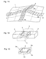
- Fig. 1A is a sketch showing the first step of the method of combining partially measured data according to the present invention, and Figs. 1B and 1C generally show the second step of the method.
- the surface shape of the object 1 is measured by changing the positions and/or directions of measurement, and a plurality of sets of partially measured data 2 including those of common parts 2a are determined.
- This object 1 being measured is a continuous body without holes or discontinuities, such as a mock-up model of an automobile.
- Continuity levels are predetermined, for instance, by the following four step procedure which assumes that an identity tolerance (IDTOL) has been given beforehand, whereby a group of measurement points of partially measured data 2 can be regarded as being identical.
- IDTTOL identity tolerance
- G0 The distance between a pair of points belonging to two adjacent groups of partial measurement points is IDTOL or less. (Point contact)
- G1 All distances between pair of points included in an overlapping part in the outermost portion of two adjacent groups of partially measured points are IDTOL or less. (Line contact)
- G2 For all pairs of points included in an overlapping part of two adjacent groups of partially measured points (called boundary point groups), the approximate tangents defined for each pair totally coincide.
- G3 For all pairs of points included in a boundary point group of two adjacent groups of partially measured points, the distribution of approximate principal curvatures defined for each pair totally coincide.
- the texture is the geometrical pattern of a surface.
- a no contact measuring instrument or digitizer such as an aperture interferometer or a range finder is used.
- partially measured data 2 are measured and/or digitized so that there is an overlap at all times.
- the overlapped ranges 3a of adjacent common parts 2a in the measurement error ranges 3 are determined for all partially measured data 2.
- the measurement error ranges 3 include the positioning accuracies of the no contact measuring instrument or digitizer as well as the measurement errors of the sensor.
- each polyhedron (in the measurement error ranges) obtained by offsetting each partially measured data point 2, as described below, is intersected by a set of a maximum of four adjacent ranges, and when the intersection is an empty set, it is concluded that there is no solution.
- the inability to make a combination is decided when there are no overlapped ranges 3a in the aforementioned measurement error ranges 3 in (c) above.
- the continuity at each of the levels G0 to G3 is adjusted while the four corners of each view are kept in the intersection range.
- the product range is fixed in the absolute coordinates, so there are no cumulative errors.
- a sensor such as an interferometer
- the image can be regarded as a rigid body (a three-dimensional body which cannot be deformed) because of the difference in the accuracies.
- the partially measured data are considered as individual rigid parts, and that they are combined into an assembly.
- a rigid body can be represented by a point fixed to the body (called the Representing Point for short) and three orthogonal coordinates (posture).
- the Representing Point can be the center of gravity, for example, and travels when the rigid body moves.
- the Representing Point need not be inside the rigid body.
- the conditions for the incorporation of the boundary point group of the four corners of the partially measured data in a product range that has already been obtained by rough checking can be expressed by a set of linear inequalities (that is, simultaneous linear inequalities) to determine the range in which the free, fixed points of the partially measured data can exist. Geometrically, this is equivalent to a polytope (a convex hull with only one peak).
- the positional vector of the center of gravity of the boundary point group of the four corners relative to the Representing Point is determined, and is rotated and translated by a linear approximation.
- a new Representing Point and restrictions to be satisfied in the local coordinates after incorporation are determined.
- the scope of the Representing Point and postures of the rigid body after being translated and rotated differentially relative to the reference (a linear approximation is substituted for this.)
- the conditions for which the overlapped parts of the adjacent partially measured data are included in the product of the measurement error ranges can be expressed as a development from the condition that a point is included in a convex polyhedron (a set of linear inequalities).
- each point in the rigid body is expressed by equation 1 (with an already known constant) with its center of gravity (g) and relative positional vector (r i ) from the center of gravity, and differential movements ( ⁇ x i , ⁇ y i , ⁇ z i ) and differential rotations ( ⁇ a i , ⁇ b i , ⁇ c i ) around the x, y and z axes are assumed for each set of partially measured data (with suffix i) in the measurement error ranges.
- the ranges in which the partially measured data can exist during the fine stitching are replaced by linear restrictions on six variables ( ⁇ x i , ⁇ y i , ⁇ z i , ⁇ a i , ⁇ b i , ⁇ c i ), i.e. the differential parallel and rotational components, for each set of partially measured data.
- the continuity conditions for each of the cases of surface contact, line contact, and point contact are modified depending on the connection levels, while the positional vectors relative to the Representing Points are determined and the restrictions on the positions and postures relative to the Representing Points are increased, in the same way as for one body.
- Continuousity conditions are modified means that although the number of the aforementioned six variables is the same as the number of sets of partially measured data, the variables are not independent, but are restricted by the various continuity levels; for G3, the conditions are the same as for a one-body problem (0 degrees of freedom); for G2, two degrees of freedom are added which permit translation in a plane while the posture is fixed; for G1, one degree of freedom is added which permits a differential angular rotation for each connection about the rotational axis of the contact line, and two degrees of freedom are added to permit differential translation of the axis in a plane (three degrees of freedom in total); for G0, two degrees of freedom are added which permit differential angular rotations about axis through the center of the contact point, and two degrees of freedom are added which permit differential translation movements of the contact point in a plane (a total of four degrees of freedom).
- a method of obtaining a region from a group of points is disclosed, for example, in B. Chazelle: "An Optimal Convex Hull Algorithm in Any Fixed Dimension,” Discrete Computational Geometry, 10:377-409, 1993.
- the overlapped ranges 3a of the adjacent common parts 2a are determined in the measurement error ranges 3, therefore the presence or absence of the overlapped ranges 3a can be identified very quickly.
- the measured data include errors that are greater than the inherent measurement errors, so even if the calculations are iterated during combination, no solutions can eventually be obtained. Therefore, (C) when there are no overlapped ranges (3a), a decision is made that a combination cannot be achieved to avoid useless repeated calculations.
Landscapes
- Physics & Mathematics (AREA)
- General Physics & Mathematics (AREA)
- Length Measuring Devices With Unspecified Measuring Means (AREA)
- Processing Or Creating Images (AREA)
- Length Measuring Devices By Optical Means (AREA)
Claims (2)
- Procédé de combinaison de données partiellement mesurées, comprenant les étapes consistant à :(A) mesurer la forme de surface d'un objet (1) en faisant varier la position et/ou la direction de la mesure, et en faisant l'acquisition d'une pluralité de jeux de données partiellement mesurées qui comprennent des parties communes (2a),(B) pour tous les jeux de données partiellement mesurées, déterminer s'il existe des plages de chevauchement (3a) pour les parties communes adjacentes (2a) dans les plages d'erreurs de mesure (3),(C) lorsqu'il n'y a pas de plage de chevauchement (3a), prendre une décision selon laquelle aucune combinaison ne peut être effectuée, et(D) lorsqu'il y a des plages de chevauchement (3a), combiner les parties communes de chaque jeu de données partiellement mesurées.
- Procédé de combinaison de données partiellement mesurées selon la revendication 1, comprenant les étapes consistant à :(E) transformer les coordonnées de chaque jeu de données partiellement mesurées de sorte qu'un groupe de données positionnelles des parties communes (2a) tombe dans les plages de chevauchement (3a) à ladite étape (D), et(F) combiner les parties communes (2a) pendant que les parties communes de chaque jeu de données partiellement mesurées sont maintenues dans les plages de chevauchement (3a) même après avoir transformé les coordonnées.
Applications Claiming Priority (2)
| Application Number | Priority Date | Filing Date | Title |
|---|---|---|---|
| JP14775699 | 1999-05-27 | ||
| JP14775699A JP3403668B2 (ja) | 1999-05-27 | 1999-05-27 | 部分測定データの合成方法 |
Publications (3)
| Publication Number | Publication Date |
|---|---|
| EP1055906A2 EP1055906A2 (fr) | 2000-11-29 |
| EP1055906A3 EP1055906A3 (fr) | 2001-05-02 |
| EP1055906B1 true EP1055906B1 (fr) | 2006-09-13 |
Family
ID=15437455
Family Applications (1)
| Application Number | Title | Priority Date | Filing Date |
|---|---|---|---|
| EP00111423A Expired - Lifetime EP1055906B1 (fr) | 1999-05-27 | 2000-05-26 | Procédé pour combiner des données partiellement mesurées |
Country Status (5)
| Country | Link |
|---|---|
| US (1) | US6611791B1 (fr) |
| EP (1) | EP1055906B1 (fr) |
| JP (1) | JP3403668B2 (fr) |
| CA (1) | CA2309071A1 (fr) |
| DE (1) | DE60030624D1 (fr) |
Families Citing this family (13)
| Publication number | Priority date | Publication date | Assignee | Title |
|---|---|---|---|---|
| US6956657B2 (en) * | 2001-12-18 | 2005-10-18 | Qed Technologies, Inc. | Method for self-calibrated sub-aperture stitching for surface figure measurement |
| JP3894063B2 (ja) * | 2002-07-12 | 2007-03-14 | 株式会社日立製作所 | 立体形状データ変換装置および立体形状データ変換方法 |
| US7221461B2 (en) * | 2004-08-13 | 2007-05-22 | Zygo Corporation | Method and apparatus for interferometric measurement of components with large aspect ratios |
| GB2422015B (en) | 2005-02-01 | 2007-02-28 | Taylor Hobson Ltd | A metrological instrument |
| DE102006005958A1 (de) * | 2006-02-08 | 2007-08-16 | Kuka Roboter Gmbh | Verfahren zum Erzeugen eines Umgebungsbildes |
| JP5424581B2 (ja) * | 2008-06-06 | 2014-02-26 | キヤノン株式会社 | 部分測定を合成する形状測定方法 |
| JP5312100B2 (ja) | 2009-03-03 | 2013-10-09 | キヤノン株式会社 | 測定方法及び測定装置 |
| JP5639773B2 (ja) * | 2010-03-11 | 2014-12-10 | 株式会社ミツトヨ | 画像測定機 |
| US9417047B2 (en) * | 2014-08-11 | 2016-08-16 | Toyota Motor Engineering & Manufacturing North America, Inc. | Three-dimensional edge profile determination |
| JP6293049B2 (ja) * | 2014-12-26 | 2018-03-14 | 株式会社Hielero | 点群データ取得システム及びその方法 |
| JP6903987B2 (ja) * | 2017-03-24 | 2021-07-14 | 富士通株式会社 | 情報処理プログラム、情報処理方法、および情報処理装置 |
| EP3511674B1 (fr) * | 2018-01-15 | 2021-07-21 | Mitutoyo Corporation | Procédé et système pour mesurer le profil de hauteur d'une surface d'un objet, et programme informatique et support de données à utiliser dans le procédé |
| CN112013784B (zh) * | 2019-05-28 | 2021-09-28 | 深圳中科飞测科技股份有限公司 | 一种检测方法和检测系统 |
Family Cites Families (4)
| Publication number | Priority date | Publication date | Assignee | Title |
|---|---|---|---|---|
| US5831621A (en) | 1996-10-21 | 1998-11-03 | The Trustees Of The University Of Pennyslvania | Positional space solution to the next best view problem |
| JP3309743B2 (ja) * | 1996-11-27 | 2002-07-29 | 富士ゼロックス株式会社 | 形状測定方法及び装置 |
| US5987189A (en) * | 1996-12-20 | 1999-11-16 | Wyko Corporation | Method of combining multiple sets of overlapping surface-profile interferometric data to produce a continuous composite map |
| US6078701A (en) * | 1997-08-01 | 2000-06-20 | Sarnoff Corporation | Method and apparatus for performing local to global multiframe alignment to construct mosaic images |
-
1999
- 1999-05-27 JP JP14775699A patent/JP3403668B2/ja not_active Expired - Fee Related
-
2000
- 2000-05-18 US US09/572,340 patent/US6611791B1/en not_active Expired - Fee Related
- 2000-05-19 CA CA002309071A patent/CA2309071A1/fr not_active Abandoned
- 2000-05-26 DE DE60030624T patent/DE60030624D1/de not_active Expired - Lifetime
- 2000-05-26 EP EP00111423A patent/EP1055906B1/fr not_active Expired - Lifetime
Also Published As
| Publication number | Publication date |
|---|---|
| EP1055906A2 (fr) | 2000-11-29 |
| JP3403668B2 (ja) | 2003-05-06 |
| US6611791B1 (en) | 2003-08-26 |
| EP1055906A3 (fr) | 2001-05-02 |
| JP2000337862A (ja) | 2000-12-08 |
| CA2309071A1 (fr) | 2000-11-27 |
| DE60030624D1 (de) | 2006-10-26 |
Similar Documents
| Publication | Publication Date | Title |
|---|---|---|
| US6611791B1 (en) | Method for combining partially measured data | |
| Li et al. | Free-form surface inspection techniques state of the art review | |
| Lee et al. | Automated inspection planning of free-form shape parts by laser scanning | |
| Son et al. | Automated laser scanning system for reverse engineering and inspection | |
| US7565216B2 (en) | Clearance measurement of manufactured parts | |
| US7487063B2 (en) | Three-dimensional modeling from arbitrary three-dimensional curves | |
| Menq et al. | Curve and surface approximation from CMM measurement data | |
| US5960379A (en) | Method of and apparatus for measuring shape | |
| Lai et al. | Registration and data merging for multiple sets of scan data | |
| Mason et al. | Automatic sensor placement for accurate dimensional inspection | |
| Fan et al. | Optimal shape error analysis of the matching image for a free-form surface | |
| Lee et al. | A framework for laser scan planning of freeform surfaces | |
| Yang et al. | Error analysis of 3D shape construction from structured lighting | |
| US20250033211A1 (en) | Robotic path planning | |
| Yang et al. | Error analysis and planning accuracy for dimensional measurement in active vision inspection | |
| CN118411462A (zh) | 一种基于激光与超声信息融合的异形空腔构件模型重建方法 | |
| Gordon et al. | Real-time part position sensing | |
| Mason | Conceptual model of the convergent multistation network configuration task | |
| EP1497794B1 (fr) | Logiciel de calibrage utilise dans la reconstruction de surface d'objets de dimension reduite | |
| EP1030162B1 (fr) | Procede d'evaluation d'erreurs de forme d'une surface courbe à forme libre | |
| US6683977B1 (en) | Method of taking three-dimensional measurements of object surfaces | |
| Wallack et al. | Robust algorithms for object localization | |
| Ristic et al. | Contact probe radius compensation using computer aided design models | |
| Suh et al. | Compensating probe radius in free surface modelling with CMM: simulation and experiment | |
| Krishnan et al. | Monocular pose of a rigid body using point landmarks |
Legal Events
| Date | Code | Title | Description |
|---|---|---|---|
| PUAI | Public reference made under article 153(3) epc to a published international application that has entered the european phase |
Free format text: ORIGINAL CODE: 0009012 |
|
| AK | Designated contracting states |
Kind code of ref document: A2 Designated state(s): DE FR GB IT |
|
| AX | Request for extension of the european patent |
Free format text: AL;LT;LV;MK;RO;SI |
|
| PUAL | Search report despatched |
Free format text: ORIGINAL CODE: 0009013 |
|
| AK | Designated contracting states |
Kind code of ref document: A3 Designated state(s): AT BE CH CY DE DK ES FI FR GB GR IE IT LI LU MC NL PT SE |
|
| AX | Request for extension of the european patent |
Free format text: AL;LT;LV;MK;RO;SI |
|
| 17P | Request for examination filed |
Effective date: 20010531 |
|
| AKX | Designation fees paid |
Free format text: DE FR GB IT |
|
| GRAP | Despatch of communication of intention to grant a patent |
Free format text: ORIGINAL CODE: EPIDOSNIGR1 |
|
| GRAS | Grant fee paid |
Free format text: ORIGINAL CODE: EPIDOSNIGR3 |
|
| GRAA | (expected) grant |
Free format text: ORIGINAL CODE: 0009210 |
|
| AK | Designated contracting states |
Kind code of ref document: B1 Designated state(s): DE FR GB IT |
|
| PG25 | Lapsed in a contracting state [announced via postgrant information from national office to epo] |
Ref country code: IT Free format text: LAPSE BECAUSE OF FAILURE TO SUBMIT A TRANSLATION OF THE DESCRIPTION OR TO PAY THE FEE WITHIN THE PRESCRIBED TIME-LIMIT;WARNING: LAPSES OF ITALIAN PATENTS WITH EFFECTIVE DATE BEFORE 2007 MAY HAVE OCCURRED AT ANY TIME BEFORE 2007. THE CORRECT EFFECTIVE DATE MAY BE DIFFERENT FROM THE ONE RECORDED. Effective date: 20060913 |
|
| REG | Reference to a national code |
Ref country code: GB Ref legal event code: FG4D |
|
| REF | Corresponds to: |
Ref document number: 60030624 Country of ref document: DE Date of ref document: 20061026 Kind code of ref document: P |
|
| PG25 | Lapsed in a contracting state [announced via postgrant information from national office to epo] |
Ref country code: DE Free format text: LAPSE BECAUSE OF FAILURE TO SUBMIT A TRANSLATION OF THE DESCRIPTION OR TO PAY THE FEE WITHIN THE PRESCRIBED TIME-LIMIT Effective date: 20061214 |
|
| ET | Fr: translation filed | ||
| PLBE | No opposition filed within time limit |
Free format text: ORIGINAL CODE: 0009261 |
|
| STAA | Information on the status of an ep patent application or granted ep patent |
Free format text: STATUS: NO OPPOSITION FILED WITHIN TIME LIMIT |
|
| 26N | No opposition filed |
Effective date: 20070614 |
|
| GBPC | Gb: european patent ceased through non-payment of renewal fee |
Effective date: 20070526 |
|
| REG | Reference to a national code |
Ref country code: FR Ref legal event code: ST Effective date: 20080131 |
|
| PG25 | Lapsed in a contracting state [announced via postgrant information from national office to epo] |
Ref country code: GB Free format text: LAPSE BECAUSE OF NON-PAYMENT OF DUE FEES Effective date: 20070526 |
|
| PG25 | Lapsed in a contracting state [announced via postgrant information from national office to epo] |
Ref country code: FR Free format text: LAPSE BECAUSE OF NON-PAYMENT OF DUE FEES Effective date: 20070531 |