EP1056011A2 - Procédé et système pour récupérer des données - Google Patents
Procédé et système pour récupérer des données Download PDFInfo
- Publication number
- EP1056011A2 EP1056011A2 EP20000201532 EP00201532A EP1056011A2 EP 1056011 A2 EP1056011 A2 EP 1056011A2 EP 20000201532 EP20000201532 EP 20000201532 EP 00201532 A EP00201532 A EP 00201532A EP 1056011 A2 EP1056011 A2 EP 1056011A2
- Authority
- EP
- European Patent Office
- Prior art keywords
- data center
- data
- failure
- critical
- recovery
- Prior art date
- Legal status (The legal status is an assumption and is not a legal conclusion. Google has not performed a legal analysis and makes no representation as to the accuracy of the status listed.)
- Withdrawn
Links
Images



Classifications
-
- G—PHYSICS
- G06—COMPUTING OR CALCULATING; COUNTING
- G06F—ELECTRIC DIGITAL DATA PROCESSING
- G06F11/00—Error detection; Error correction; Monitoring
- G06F11/07—Responding to the occurrence of a fault, e.g. fault tolerance
- G06F11/16—Error detection or correction of the data by redundancy in hardware
- G06F11/20—Error detection or correction of the data by redundancy in hardware using active fault-masking, e.g. by switching out faulty elements or by switching in spare elements
- G06F11/2053—Error detection or correction of the data by redundancy in hardware using active fault-masking, e.g. by switching out faulty elements or by switching in spare elements where persistent mass storage functionality or persistent mass storage control functionality is redundant
- G06F11/2056—Error detection or correction of the data by redundancy in hardware using active fault-masking, e.g. by switching out faulty elements or by switching in spare elements where persistent mass storage functionality or persistent mass storage control functionality is redundant by mirroring
- G06F11/2071—Error detection or correction of the data by redundancy in hardware using active fault-masking, e.g. by switching out faulty elements or by switching in spare elements where persistent mass storage functionality or persistent mass storage control functionality is redundant by mirroring using a plurality of controllers
- G06F11/2074—Asynchronous techniques
-
- G—PHYSICS
- G06—COMPUTING OR CALCULATING; COUNTING
- G06F—ELECTRIC DIGITAL DATA PROCESSING
- G06F11/00—Error detection; Error correction; Monitoring
- G06F11/07—Responding to the occurrence of a fault, e.g. fault tolerance
- G06F11/16—Error detection or correction of the data by redundancy in hardware
- G06F11/20—Error detection or correction of the data by redundancy in hardware using active fault-masking, e.g. by switching out faulty elements or by switching in spare elements
- G06F11/2053—Error detection or correction of the data by redundancy in hardware using active fault-masking, e.g. by switching out faulty elements or by switching in spare elements where persistent mass storage functionality or persistent mass storage control functionality is redundant
- G06F11/2056—Error detection or correction of the data by redundancy in hardware using active fault-masking, e.g. by switching out faulty elements or by switching in spare elements where persistent mass storage functionality or persistent mass storage control functionality is redundant by mirroring
- G06F11/2064—Error detection or correction of the data by redundancy in hardware using active fault-masking, e.g. by switching out faulty elements or by switching in spare elements where persistent mass storage functionality or persistent mass storage control functionality is redundant by mirroring while ensuring consistency
Definitions
- This invention relates to a method and system of implementing data recovery on a large scale. Typically by large scale is meant, for example, terabytes of data. More specifically, the invention relates to a method and system of implementing data recovery to facilitate uninterrupted continuation of business operations, and in particular, in a banking/financial transaction environment where millions of activities or transactions are conducted daily.
- the types of disasters which require this type of backup operation are those that cause the mainframe data center not to function. Examples of such disasters include fire, major electrical failure or other like causes. Specifically, a "disaster event" is an event that renders the main computer center unusable and causes implementation of contingency plans as described previously.
- the traditional recovery processes are inadequate because of the amount of time it takes in transit for the tapes to arrive at the off-site facility, as well the time required for restoration or copying of tape data from magnetic tape onto disk.
- the process currently can take up to 48 hours, and by the time the business applications are run and resynchronized with each other, total elapsed time can be 2 or 3 days.
- a system and method are provided which allow mirroring data into a recovery site in real time, for example, during daytime operation, so that as data is written to disk in the primary data center location, it is concurrently copied to disk at the recovery site, thereby eliminating the use of separate magnetic media for that purpose.
- real time mirroring of data is provided to a separate facility which is connected to the mainframe data center through appropriate communication circuits for example, through T3 circuits.
- the primary data center is upgraded with appropriate hardware, firmware and software, and a communications infrastructure is built between the primary data center location and a backup site, with sufficient hardware installed at the recovery site and through software, the operations of the primary data center to keep the remote data center disk current with the primary data center's data are controlled.
- existing disk storage technology for example, available from EMC Corporation is deployed.
- Disk subsystem(s) reside at the primary site and at the remote backup site, and existing software available from EMC under the name Symmetrix® Remote Data Facility (SRDF) provides the mirroring capability.
- SRDF Symmetrix® Remote Data Facility
- the system as implemented allows recovery during the "on-line” business day as well as allowing for "batch”, typically night-time recovery.
- the invention is directed to a method of recovering system function and data in the event of failure of on-line systems connected to a data center.
- a first data center having a predetermined equipment configuration is first established.
- a second data center having an equipment configuration which is substantially equivalent to the equipment configuration at the first data center is also established.
- critical on-line data is written in real time to a disk store at the first data center and to a mirror disk store at the second data center.
- critical is meant the data required to enable the business unit or units to continue their mission critical computer based processing.
- Examples of critical on-line functions to be recovered during an on-line day include, in the event of a banking operation, account balance inquiry, enabling of transmission interfaces, primarily with customers, application support staff data center applications, customer support and other necessary recovery steps required before making the system available to other users. Thereafter, restoration and recovery of data needed for nightly batch processing and restoration of other non-critical applications will then take place once the most critical functions are recovered, via traditional manner.
- critical batch processes are also backed up by storing batch data and processes on a mirror disk at the second data center.
- critical batch processes are backed up by a combination of disk mirroring and by creating magnetic tape files within a tape silo at the second data center.
- the invention is directed to a system for recovering systems functions and data in the event of failure of on-line systems connected to a data center.
- a first data center is established having a predetermined equipment configuration
- a second data center is also established having an equipment configuration which is substantially equivalent to the equipment configuration at the first data center.
- a first connection is provided between the two data centers for writing critical on-line data in real time to a disk store at the first data center and to a mirror disk store at the second data center.
- a second connection serves to back up critical batch processes during daytime operation of the first data center by storing batch data and processes on a mirror disk at the second data center.
- a third connection is configured for backing up critical batch processes during nighttime operation of the first data center by creating magnetic tape files critical for nightly batch recovery from disk files at the first data center onto a tape silo at the second data center.
- the second data center is further programmed for determining the state of the system at the time of a failure, with a scheduling subsystem mirrored to run on the equipment at the second data center, for determining which systems need to be restarted.
- batch recovery can be accomplished through a combination of a remote disk mirroring system, complemented by a remote tape vaulting process.
- a tape silo(s) typically available from Storage Technology Inc., is installed in the remote data center and connected through a network infrastructure to the primary data center.
- a determination is made as to which magnetic tape flies are critical for nightly batch recovery, and instead of creating them locally within the primary data center, are directed for creation within the remote silo at the recovery location. This determination is made by way of a software reporting system known as CD/IBR, commercially available from Implementation and Conversion Services, Inc.
- the software can be locally customized in a routine manner depending on parameters selected to be important for identifying critical files to be recovered.
- the remote mirroring is implemented on a disk volume basis. For example, all data on a designated disk is mirrored. A determination is made at the primary site as to which volumes or subsystems are critical for recovery at the remote site. Once the identification is made, the mirroring process is appropriately configured. Specifically, each of the required volumes is identified to the remote data facility, and the remote mirroring capability is activated against that particular volume or volumes.
- on-line portion i.e., the daytime portion of the recovery
- CICS system conventional and well known to those of ordinary skill in the art
- DB2, IDMS or other on-line database or transaction monitors.
- the recovery strategy as implemented herein allows for recovery to the point in time of the failure.
- the daytime recovery does not rely on any magnetic tape media in the remote silo.
- the system as implemented is fully recoverable from remote mirrored disks and in that manner can be recovered very quickly and substantially to the point in time of the failure.
- recording is achieved at both locations substantially simultaneously as data comes in as a result of semi-synchronous mirroring, and thereby provides for point in time recovery of on-line data.
- This includes transmitting customer and internal data to both the primary and secondary data site. In the event of failure, this eliminates the need for any data retransmission.
- an equipment configuration is provided at the recovery site that is essentially equivalent to the equipment configuration at the primary site, and when a disaster occurs, the recovery plan at the recovery site is initiated. This can be achieved by a phone call to the provider of the service at the remote recovery site which then triggers a series of events.
- the first step is that the equipment configuration at the recovery site will be prepared immediately for operation and configured according to prearranged specifications.
- the system is then made available to begin the start of processes which allows initializing of the system software, and start up of the operating system, for example, an MVS mainframe operating system software environment.
- Other environments in which the invention can be deployed include a variety of midrange platforms such as UNIX/AIX, VAX/VMS, etc.
- An automated scheduling subsystem is started and used to determine exactly the state of the system at the time of the failure, and will allow the operations staff to determine and know which systems need to be recovered. After that investigation is conducted, the systems that were operating at the time of the failure are then restarted.
- One aspect of the system is a device known as a link utilization monitor which is integrated into the software and hardware deployed. More particularly, this monitor facilitates maintaining system performance at the primary site and provides sufficient communications bandwidth between the sites so that the process at the primary site is not degraded in any manner while remote mirroring is operational.
- a key to providing sufficient bandwidth between sites is the ability to be able to determine how much available bandwidth is currently used, especially during peak periods, so that adequate capacity can be provided, thereby avoiding performance or response degradation at the primary site.
- the link utilization monitor provides that function and information to make the infrastructure manageable.
- a weakness in disk mirroring technology has been its inability to maintain logical data integrity across disk subsystems.
- this risk is mitigated by implementing software which allows identification of potential data integrity exposures and for taking corrective action.
- An example of such a condition is that if a database were to reside on a subsystem, and a recovery journal for the database were located on a second subsystem, if a failure were to occur during the active operation of the database, recovery of the application at the remote site is potentially problematic depending on the exact timing and synchronization levels between the journal and the actual database.
- software is implemented that recognizes various logical data entities and reports on the data entities.
- the software will report that the journal for the particular database has migrated onto a subsystem and represents a potential recovery or integrity exposure. Alter an alert is issued, corrective action is then taken. More particularly, the software automatically detects failures in the mirroring infrastructure, issues an automatic alert or warning to support personnel and a manual correction is implemented.
- Another aspect of the system is the ability to test at the remote site for the adequacy and effectiveness of the mirroring process simultaneous with the mirroring process itself.
- Such testing is achieved by physically and logically separating a copy of disk data at the remote site.
- the system provides for four literal copies of all data, i.e., two copies at the primary site, for disk recovery purposes, should there be a local disk failure, and two copies of the mirrored data at the remote site.
- the function is achieved by logically separating and physically separating the fourth copy at the remote site and treating it as a separate logical system and database using that copy for recovery testing, while the other copy at the remote site is still active in mirroring all data transactions at the primary data center.
- the individual mirrored disks can be automatically decoupled under program control.
- the decoupled mirrored disk can be used to validate the integrity of the mirrored data and the remote or alternate data center configuration.
- the fourth copy is then refreshed from the third copy or the other copy at the remote site, and synchronized so that both versions continue to be synchronized from that moment on until the next time that it is broken away for a continuity test i.e., the decoupled disk is automatically recoupled across the entire disk configuration under program control.
- recovery time of applications is reduced from, in some cases several days, to two and half hours.
- this is achieved by implementing disk caching of tape data.
- This aspect is implemented in a case of the nightly batch recovery into a remote silo.
- certain critical batch data is staged onto a mirrored disk to the recovery site. It has a relatively short life span on the disk and is downloaded off the disk onto a local tape at the primary data center.
- the communication linkages implemented are very robust, and implement the latest SONET Ring technology currently available from communications providers to provide alternate routing in the case of the loss of any one of the network links.
- EMC's SRDF Although the invention is described with reference to EMC's SRDF, it will be readily apparent to those of ordinary skill in the art that alternative systems may be substituted.
- EMC's SRDF a system such as that available from Hitachi "Data Systems” Hitachi Remote Copy (HRC) and Hitachi Open Remote Copy (HORC) disk mirroring technology can be deployed in place of the EMC systems as will be readily apparent to those of ordinary skill in the art.
- IBM Corporation can provide such a system.
- a SONET Ring 17 is installed between a primary data center 13 a secondary data center 15. Twelve T3 circuits are deployed, of which six are allocated for disk mirroring, and five are allocated for remote tape vaulting. The remaining T3 circuit is deployed across the vaulting infrastructure based upon capacity requirements.
- Fig. 2 illustrates in greater detail the specific T3 links 41 between the primary data center 13 and the secondary data center 15. Of special significance is the fact that, for example, the T3 circuits are security protected by data encryption technology, thereby providing a secure public communications facility. This is shown in Fig. 1 with encryptors 32 connected within the system.
- Figs. 4 and 5 illustrate remote silo configurations.
- the silo configuration is based on the number, size and frequency of back-ups necessary to accomplish intraday and nightly batch recovery. With these backups off-site, i.e., at the recovery data center, batch recovery can be accomplished exactly as it would if there was a local primary data center failure, i.e., a CPU failure in midstream.
- the files for local recovery will normally exist for a short period of time and will not be used as input to a scheduled production process.
- the system provides mirroring from a primary site to a remote site in the event of catastrophic failure, it also provides for re-establishing operations at the primary site once the failure(s) is corrected.
- reverse mirroring the secondary site to a primary site is achieved in the same manner that mirroring from the primary site to the secondary site can be achieved.
- the primary site becomes the mirroring remote site and the remote site operates as the primary site.
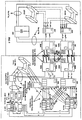
- the system 11 of the invention is shown as having a primary data center 13 connected through means of SONET Ring technology 17 employing T3 circuits to a secondary data center 15.
- the direct access storage devices or drive used in the system are shown in the system as disk storage configurations, typically direct access storage device (DASD) arrays 25 and 27 at the respective data centers 13 and 15, and each having multiple disks as part of the array.
- DASD direct access storage device
- These devices may be typically interconnected through the SONET Ring 17 employing the T3 circuits and are interconnected through the use of storage networking systems more generally shown as elements 45 in Fig. 3 interconnected by the T3 links 41 to connect to the DASD systems 47.
- Other types of interconnections can be accomplished through use of lease lines of varying speeds, T1 facilities, native T3 circuits, ATM connections and others.
- a monitoring device 28 known as a link utilization monitor (LUM), particularly at the primary site, monitors network utilization, i.e., T3, to determine the available capacity of the connection between the primary and secondary data centers. This is done by periodic sampling of the utilization under programmed control, and displaying information about the line utilization.
- the storage networking system is one which was previously available as the 9800 SNS from General Signal Corporation, now having been acquired by SPX Corporation and available from its subsidiary Inrange Technologies Corporation on a updated basis, still employing the 9800 series designation, as the 9801 SNS Storage Network System.
- the systems 45 are networking systems for business continuance and disaster recovery and provide performance storage networking at low bandwidth cost.
- DASD disk mirroring software
- SRDF disk mirroring software available from EMC Corporation
- Hitachi Data System IBM or others
- communications between the two data centers 13 and 15 is enabled by means of the storage network system connections shown in greater detail in Fig. 3 with respect to the various interconnections between the networking systems 45 and the DASD devices 47 of the arrays 25 and 27.
- the typical configuration for mirroring involves three of the DASD units 47 at each site such that the subsystems are physically housed in a secured space within each of the data center environments, and the respective units 47 are connected by three pairs of T3 lines with channel extenders and encryptors.
- the SRDF software running at the respective site enables mirroring at the volume level of' selected volumes, the number of volumes being mirrored initially are typically about 600 volumes (approximately two (2) terabytes of data), which requires recovery on a large scale.
- the DASD array 27 is connected to a dedicated ESCON switch within a switch 29.
- the switch 29 connects to dedicated front end processors 19.
- the dedicated front end processors 19 are connected by T1 lines to the customer network and infrastructure 23.
- a print pool 37 also connected to the matrix switch 29 is a print pool 37, a shared terminal pool 35, a shared DASD pool 31, a switch controller (not numbered), a shared tape pool 33, and a shared CPU pool 39, as well as a shared front end processor pool 21.
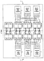
- Fig. 4 shows in greater detail a remote tape management system to allow vault tape backups.
- the silo at the recovery site 15 is connected to the primary site 13 via five T3 lines 41. Data flow is from a central processing unit 49 through ESCON channels to DASD devices 47 of array 25 through the T3 lines 41 to the DASD devices 47 of array 27 at the recovery site 15 and to a tape silo 59 which includes 16 tape units in two silos and is configured for redundancy.
- backups are directed to local tape units in the primary data center 13 and propagated to the remote silos 59 once the connections are restored.
- the flow of data is controlled by a channel switch 51 at the primary data center 13 and controlled at the secondary or recovery site 15 through a library management unit (LMU) control unit 53, which provides commands to a robot inside the tape/silo in a conventional manner, and through an ESCON director unit 55.
- LMU library management unit
- FIG. 5 A more detailed configuration for conducting tape vault operations is further shown in Fig. 5 wherein the various elements are also shown numbered, and the interconnections and the operation thereof will be readily apparent to those of ordinary skill in the art and similar to that of Fig. 4.
- the invention is implemented in the environment of global banking in which many financial services generate transaction flow to and from, in this case, a banking data center, to initiate transactions on behalf of the bank's clients and/or internal users.
- Services provided over such a network from a data processing center include such services as security trading, both within the bank implementing the data processing center, as well as outside of the individual bank's system.
- checking systems receive and generate batch feeds from and to operating units within and outside the bank's environment.
- Another function implemented through the network includes fund transfers which are initiated by customers and posted in real time. Thus, it becomes important to be able to recover these functions, many of which are considered critical on an expedited basis.
- critical systems and functions are those which are initially recovered prior to recovering other functions and data in the event of system failure.
- functions which are considered critical include checking, such as corporate checking and financial institutions checking.
- Other functions considered important are DB2-based applications that provide same-date posting to account balances, and supporting interaccount aggregation
- electronic banking to corporate customers, check processing control systems for various regions, applications that process remittances, support lock box operations, applications that support multi-currency transactions, and such other systems as billing applications, electronic check managers and global check systems are all considered critical and are the first to be recovered in the event of a failure.
- the following timeline provides an example of the typical recovery window for the system and method in accordance with the invention.
- the target recovery window for critical systems are measured from the time of declaration of a disaster. They are as follows:
- recovery is accomplished by switching the front-end network, readying and IPLing the system, establishing the connections to key user locations, activating critical applications and support systems (for example, TSO, scheduling subsystems, security subsystems, CICS regions, etc.), allowing application support staff and operations to conduct initial investigation of application and transactions status.
- critical applications and support systems for example, TSO, scheduling subsystems, security subsystems, CICS regions, etc.
- the back up of system and application files critical to recovery during the on-line day utilizes "volume" based disk mirroring.
- Critical data is written in substantially real-time, i.e., in semi-synchronous mode, to corresponding target disk volumes at the back-up site and will be made available in the recovery process.
- local mirror disks are provided at the remote site. In this manner, the failure of one or more disks at the remote site does not affect the recovery process due to provisioning of the local mirrors.
- the back up of critical batch processes during the day is implemented using a combination of disk mirroring and remote tape back up, depending on the characteristics of the process (i.e., files exceeding a given size are written to the remote silo as opposed to mirrored disk).
Landscapes
- Engineering & Computer Science (AREA)
- Theoretical Computer Science (AREA)
- Quality & Reliability (AREA)
- Physics & Mathematics (AREA)
- General Engineering & Computer Science (AREA)
- General Physics & Mathematics (AREA)
- Information Retrieval, Db Structures And Fs Structures Therefor (AREA)
Applications Claiming Priority (2)
| Application Number | Priority Date | Filing Date | Title |
|---|---|---|---|
| US13156599P | 1999-04-29 | 1999-04-29 | |
| US131565 | 1999-04-29 |
Publications (1)
| Publication Number | Publication Date |
|---|---|
| EP1056011A2 true EP1056011A2 (fr) | 2000-11-29 |
Family
ID=22450010
Family Applications (1)
| Application Number | Title | Priority Date | Filing Date |
|---|---|---|---|
| EP20000201532 Withdrawn EP1056011A2 (fr) | 1999-04-29 | 2000-04-28 | Procédé et système pour récupérer des données |
Country Status (2)
| Country | Link |
|---|---|
| EP (1) | EP1056011A2 (fr) |
| SG (1) | SG85177A1 (fr) |
Cited By (4)
| Publication number | Priority date | Publication date | Assignee | Title |
|---|---|---|---|---|
| EP1229448A3 (fr) * | 2001-01-31 | 2003-01-22 | Hewlett-Packard Company | Dispositif et méthode de sauvegarde redondante |
| EP1762939A1 (fr) * | 2005-09-09 | 2007-03-14 | Charles-Yves Bourhis | Procédé de mémorisation de données numériques dans un grand système informatique et dispositif associé |
| GB2497168A (en) * | 2011-10-27 | 2013-06-05 | Sungard Availability Services Lp | Dynamic resource allocation in recover to cloud sandbox test virtual data centres |
| CN103218256A (zh) * | 2013-04-18 | 2013-07-24 | 中国工商银行股份有限公司 | 一种主机批量的回退方法以及系统 |
Family Cites Families (3)
| Publication number | Priority date | Publication date | Assignee | Title |
|---|---|---|---|---|
| US5604863A (en) * | 1993-11-01 | 1997-02-18 | International Business Machines Corporation | Method for coordinating executing programs in a data processing system |
| US5434994A (en) * | 1994-05-23 | 1995-07-18 | International Business Machines Corporation | System and method for maintaining replicated data coherency in a data processing system |
| US5727142A (en) * | 1996-05-03 | 1998-03-10 | International Business Machines Corporation | Method for a non-disruptive host connection switch after detection of an error condition or during a host outage or failure |
-
2000
- 2000-04-28 EP EP20000201532 patent/EP1056011A2/fr not_active Withdrawn
- 2000-04-29 SG SG200002471A patent/SG85177A1/en unknown
Cited By (9)
| Publication number | Priority date | Publication date | Assignee | Title |
|---|---|---|---|---|
| EP1229448A3 (fr) * | 2001-01-31 | 2003-01-22 | Hewlett-Packard Company | Dispositif et méthode de sauvegarde redondante |
| US6662281B2 (en) | 2001-01-31 | 2003-12-09 | Hewlett-Packard Development Company, L.P. | Redundant backup device |
| EP1762939A1 (fr) * | 2005-09-09 | 2007-03-14 | Charles-Yves Bourhis | Procédé de mémorisation de données numériques dans un grand système informatique et dispositif associé |
| FR2890765A1 (fr) * | 2005-09-09 | 2007-03-16 | Charles Yves Bourhis | Procede de memorisation de donnees numeriques dans un grand systeme informatique et dispositif associe |
| GB2497168A (en) * | 2011-10-27 | 2013-06-05 | Sungard Availability Services Lp | Dynamic resource allocation in recover to cloud sandbox test virtual data centres |
| US8700946B2 (en) | 2011-10-27 | 2014-04-15 | Sungard Availability Services, Lp | Dynamic resource allocation in recover to cloud sandbox |
| GB2497168B (en) * | 2011-10-27 | 2014-06-25 | Sungard Availability Services Lp | Dynamic resource allocation in recover to cloud sandbox |
| CN103218256A (zh) * | 2013-04-18 | 2013-07-24 | 中国工商银行股份有限公司 | 一种主机批量的回退方法以及系统 |
| CN103218256B (zh) * | 2013-04-18 | 2016-04-13 | 中国工商银行股份有限公司 | 一种主机批量的回退方法以及系统 |
Also Published As
| Publication number | Publication date |
|---|---|
| SG85177A1 (en) | 2001-12-19 |
Similar Documents
| Publication | Publication Date | Title |
|---|---|---|
| US6697960B1 (en) | Method and system for recovering data to maintain business continuity | |
| US6539462B1 (en) | Remote data copy using a prospective suspend command | |
| US7627776B2 (en) | Data backup method | |
| US8401999B2 (en) | Data mirroring method | |
| US7225307B2 (en) | Apparatus, system, and method for synchronizing an asynchronous mirror volume using a synchronous mirror volume | |
| US6654752B2 (en) | Method and apparatus for independent and simultaneous access to a common data set | |
| US5870537A (en) | Concurrent switch to shadowed device for storage controller and device errors | |
| US7467168B2 (en) | Method for mirroring data at storage locations | |
| EP2366151B1 (fr) | Procédé et système de gestion de données de base dupliquées | |
| EP1639470B1 (fr) | Procede, systeme et programme pour gerer une reprise en direction d'un emplacement de memoire eloigne | |
| US7278049B2 (en) | Method, system, and program for recovery from a failure in an asynchronous data copying system | |
| US7111139B2 (en) | Data synchronization of multiple remote storage | |
| US6052758A (en) | Interface error detection and isolation in a direct access storage device DASD system | |
| CN101635638B (zh) | 一种容灾系统及其容灾方法 | |
| JP4624829B2 (ja) | データバックアップシステム及び方法 | |
| US20050160248A1 (en) | Distributed remote copy system | |
| MXPA06005797A (es) | Sistema y metodo para la recuperacion en caso de fallas. | |
| US7647357B2 (en) | Data transfer management in consistency group formation | |
| EP1056011A2 (fr) | Procédé et système pour récupérer des données | |
| Osuna et al. | Redpaper |
Legal Events
| Date | Code | Title | Description |
|---|---|---|---|
| PUAI | Public reference made under article 153(3) epc to a published international application that has entered the european phase |
Free format text: ORIGINAL CODE: 0009012 |
|
| AK | Designated contracting states |
Kind code of ref document: A2 Designated state(s): AT BE CH CY DE DK ES FI FR GB GR IE IT LI LU MC NL PT SE |
|
| AX | Request for extension of the european patent |
Free format text: AL;LT;LV;MK;RO;SI |
|
| STAA | Information on the status of an ep patent application or granted ep patent |
Free format text: STATUS: THE APPLICATION IS DEEMED TO BE WITHDRAWN |
|
| 18D | Application deemed to be withdrawn |
Effective date: 20031101 |