EP1056045A2 - Procédé et appareil de changement adaptatif de résolution d'une image numérique - Google Patents
Procédé et appareil de changement adaptatif de résolution d'une image numérique Download PDFInfo
- Publication number
- EP1056045A2 EP1056045A2 EP00304294A EP00304294A EP1056045A2 EP 1056045 A2 EP1056045 A2 EP 1056045A2 EP 00304294 A EP00304294 A EP 00304294A EP 00304294 A EP00304294 A EP 00304294A EP 1056045 A2 EP1056045 A2 EP 1056045A2
- Authority
- EP
- European Patent Office
- Prior art keywords
- conversion
- pixel
- pixels
- interpolation
- noticeable
- Prior art date
- Legal status (The legal status is an assumption and is not a legal conclusion. Google has not performed a legal analysis and makes no representation as to the accuracy of the status listed.)
- Granted
Links
Images








Classifications
-
- G—PHYSICS
- G06—COMPUTING OR CALCULATING; COUNTING
- G06T—IMAGE DATA PROCESSING OR GENERATION, IN GENERAL
- G06T3/00—Geometric image transformations in the plane of the image
- G06T3/40—Scaling of whole images or parts thereof, e.g. expanding or contracting
- G06T3/4007—Scaling of whole images or parts thereof, e.g. expanding or contracting based on interpolation, e.g. bilinear interpolation
Definitions
- Various methods for resolution-converting input low-resolution information into high-resolution information have been proposed so far.
- the proposed conventional methods are different in conversion method depending on the type of a purposed image (for example, multivalued image having gradation information for each pixel, binary image converted into binary notation by a pseudo intermediate gradation, binary image converted into binary notation by fixed threshold, or character image).
- One of the following methods is generally used as a conventional interpolation method: a closest interpolation method of arranging the same pixel values closest to the interpolation point shown in Fig. 20 and a common primary interpolation method of determining a pixel value E through the following calculation by using four points (pixel values of four points are assumed as A, B, C and D) shown in Fig. 21.
- the method shown in Fig. 20 has an advantage that the structure is simple, blocks are visually conspicuous and image quality is inferior because a pixel value is determined for each expanding block when using a purposed image for a natural image.
- the method in Fig. 21 is a method generally frequently used for expansion of a natural image.
- this method though an averaged and smoothed image quality is obtained, an edged portion or a portion requiring a sharp image quality has a dull image quality.
- important information may not be communicated to a receiver due to halation caused by interpolation.
- U.S. Patent No. 5430811 shows a non-linear interpolation art using LUT.
- an algorithm can correspond only to a magnification of doubleness ⁇ doubleness. Therefore, to obtain other magnification, it is necessary to repeat the above processing or use the processing together with other expansion processing and thus, processing becomes complex.
- a magnification of 2 n is realized in repetitive processing, it is not easy to perform control so as to provide a desired non-linearity for each pixel of high-resolution information in the final magnification.
- occurrence of jaggies cannot be avoided because values of observation pixels (original information) are not changed similarly to the case of U.S. Patent No. 5280546.
- U.S. Patent No. 5054100 also discloses non-linear interpolation.
- this art is effective for simple interpolation halation of an edge in longitudinal and transverse directions, an effect of the art cannot be obtained if video information becomes slightly complex. Occurrence of jaggies cannot be avoided similarly to the case of the above two conventional examples.
- Arts for realizing preferable resolution conversion by such as dither method and error diffusion method have been known from old times, in which linear interpolation and reconversion-into-binary-notation are applied to the resolution conversion of a binary image provided with pseudo gradation processing after passing a digital filter through the vicinity of a noticeable pixel and converting the binary image into a multivalued image (U.S. Patent No.
- the image processing apparatus of the present invention further preferably comprises:
- the image processing method of the present invention further preferably comprises:
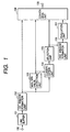
- Fig. 1 is a block diagram of an image processing apparatus of a first embodiment of the present invention. It is efficient to set an image processing apparatus of the present invention mainly in an image output unit such as a printer to which a computer is connected or a video printer to which a video signal is input. Moreover, it is possible to set the image processing apparatus as an image processing apparatus except an image output unit, application software in a host computer, or printer driver software to be output to a printer.
- a window is generally rectangular about a noticeable pixel, it is also considered that the window has a shape other than a rectangle. As shown in Fig. 2, a rectangle having a window size of 5 ⁇ 5 pixels is assumed. A noticeable pixel is M in Fig. 2.
- Numeral 103 denotes a maximum/minimum value detection unit which detects the maximum value (assumed as MAX5) and minimum value (assumed as MIN5) in 25 pixels in the window of the unit 102 and moreover detects the maximum value (assumed as MAX3) and minimum value (assumed as MIN3) in 3 ⁇ 3 pixels about the noticeable pixel.
- Numeral 140 denotes classification unit for evaluating a distribution state of pixel values in accordance with the video information in the window and classifying the type of the noticeable pixel into a type of image.
- the present embodiment locally judges a plurality of types of image attributes such as whether a noticeable pixel shows a characteristic of a natural image, a characteristic of an artificially-formed image including a CG (computer graphic), a flat portion, or an edged portion and classifies them.
- a window size for classification is set to 3 ⁇ 3 pixels about a noticeable pixel.
- Numeral 105 denotes a selection unit for selecting an optimum conversion out of a plurality of held conversion methods in a method for converting one pixel into N ⁇ M pixels in accordance with a local characteristic of a classified image.
- Numeral 106 denotes means (second window formation unit) which forms a window of a signal showing the type of a selected conversion system (hereafter referred to as conversion-system identification signal) including a noticeable pixel and refers to a conversion-system identification signal of a pixel adjacent to the noticeable pixel.
- conversion-system identification signal showing the type of a selected conversion system (hereafter referred to as conversion-system identification signal) including a noticeable pixel and refers to a conversion-system identification signal of a pixel adjacent to the noticeable pixel.
- the window size of 106 is assumed as 3 ⁇ 3 pixels about the position of the pixel M serving as a noticeable pixel (Fig. 3).
- G', H', I', L', M', N', Q', R' and S' show conversion-system identification signals of the pixels G, H, I, L, M, N, Q, R and S in Fig. 2.
- G', H', I', L', N', Q', R' and S' except M' serving as a noticeable-pixel conversion-system identification signal 3 ⁇ 3 pixels are necessary for each pixel classification unit. Therefore, a first window of at least 5 ⁇ 5 pixels (Fig. 2) is necessary.
- Numeral 107 denotes means for evaluating the content of the window of the conversion-system identification signal generated by 106.
- the means 107 evaluates a combination of conversion-system identification signals in the window.
- Numeral 108 denotes a conversion unit which generates video information of N ⁇ M pixels corresponding to a noticeable pixel in accordance with information in the window of original information (first window information), information for maximum and minimum values in the first window, and pieces of information for evaluation results in windows of a noticeable-pixel conversion-system identification signal and an adjacent-pixel conversion-system identification signal.
- Converted video information is output to a printer engine and the like through an output terminal 109.
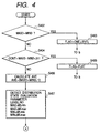
- Figs. 4 and 5 are flow charts for explaining the calculation procedure of the classification unit 104.
- MAX3 it is assumed that only 3 ⁇ 3 pixels in the first window formed by 102 are used for judgment of classification as described above.
- S402 it is judged whether MAX3 is the same as MIN3.
- MIN_diff_max shows a difference between a value (set to C) less than AVE, other than MIN3 and closest to MIN3 on one hand and MIN3 on the other.
- MIN_diff_max shows a difference between a value (set to D) less than AVE, other than MIN3 and farthest from MIN3 on one hand and MIN3 on the other.
- Evaluation 1 shows the so-called “middle-missing" distribution in which pixel values are biased to the vicinity of MAX3 and MIN3 and pixels at the middle portion are absent ⁇ 1 of (1) ⁇ or a discrete distribution in which MAX3 to MIN3 are generally uniformly quantized ⁇ 2 of (2) ⁇ , an artificially-formed image is judged.
- Evaluation 2 shows a distribution in which values close to MAX3 and MIN3 show a discrete "toothless" distribution rather saying that values close to MAX3 and MIN3 are continuous though artificiality as remarkable as that of the case of Evaluation 1 is not seen
- an original natural image is judged as video information which is previously quantized to several bits due to compression of a transmission line before an image processing apparatus input of the present embodiment.
- Pseudo-gradation video information of several bits frequently circulates through Internet that is recently quickly spread independently of an artificial image or natural image.
- a distribution showing a discrete trend more or less like the above distribution is not easily formed at an edged portion of a natural image such as a photograph input from capture means having many gradations such as an image scanner or digital camera due to weakening of MTF at the time of input and continuity is always found at a part of a distribution.
- the above described is an example of classification means.
- the classification means of the present embodiment provides six types of classifications such as ONE_LEVEL, FLAT, BI_EDGE, ART EDGE, INDEX EDGE and PICT_EDGE. It is a matter of course that classifications more than six or less than six are permitted.
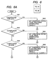
- Figs. 6A and 6B are flow charts showing a processing procedure by the selection unit.
- an optimum conversion method is selected in the above six types of classifications.
- S601 in Figs. 6A and 6B judges whether a classification signal that is an output of the classification unit is ONE_LEVEL. If the signal is ONE_LEVEL, a conversion system is set to zero-order interpolation in S602. Moreover, because conversion systems are previously sequenced and "3" which is the order of the zero-order interpolation is assigned. The order of a conversion system shows the priority of the conversion system. In the case of the present embodiment, the priority lowers as a value of an order increases.
- S603 judges whether a classification signal which is an output from the classification unit is FLAT. If the signal is FLAT, a conversion system is set to linear interpolation(primary interpolation). Number "2" which is the order of linear interpolation is assigned as the order of the conversion system.
- S605 judges whether a classification signal that is an output of the classification unit is BI_EDGE. If the signal is BI_EDGE, a conversion system is set to nonlinear interpolation in S606. Number "1" which is the order of the nonlinear interpolation is assigned as the order of the conversion system. Moreover, a condition setting number storing a condition such as a sum-of-products coefficient used for sum-of-products calculation of nonlinear interpolation is set to 1.
- ART_EDGE or not is judged in S607
- INDEX_EDGE or not is judged in S608, and PICT-EDGE or not is judged in S609. If classification does not belong to any of them, an error is output in S610.
- Fig. 8 is a block diagram of an essential portion of the conversion unit 108.
- the block enclosed by a broken line shows the conversion unit 108.
- a conversion-system identification system of a noticeable pixel output from the selection unit 105 is transmitted to a judgement unit 801 and an interpolation-condition setting unit 802.
- An evaluation result in the window of the conversion-system identification signal output from the evaluation unit 107 is similarly transmitted to the judgement unit 801.
- the judgment unit 801 outputs an instruction to a switch 803 in accordance with a judgment result and an optimum conversion system is selected.
- the switch 803 changes four types of conversion systems, that is, changes conversion systems of a zero-order interpolation unit 804, linear interpolation unit-A 805, linear interpolation unit-B 806, and nonlinear interpolation unit 807.
- Each interpolation unit performs interpolation in accordance with the pixel-value information sent from the first window.
- the nonlinear interpolation unit receives maximum/minimum value information in the window sent from a maximum/minimum value detection unit.
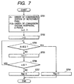
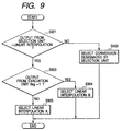
- Fig. 9 is a flow chart showing a processing procedure of the judgment unit 801.
- S901 judges whether an output from the selection unit shows linear interpolation. If the output does not show linear interpolation, a conversion system designated by the selection unit is selected in S902 to complete the operation.
- a variable flag serving as an output of the evaluation unit is set to 1.
- the linear interpolation B is selected in S904.
- the flag is not set to 1
- linear interpolation A is selected in S905 to complete the operation. That is, when a conversion system of a noticeable pixel conforms to linear interpolation and conversion systems of eight circumferential pixels conform to conversion systems having orders lower than the order of the linear interpolation, linear interpolation B is selected.
- the linear interpolation unit-A 805 is equivalent to the system (common primary interpolation method) shown for the conventional example in Fig. 21, which is means for linearly determining a relative positional relation between a sample point and an interpolation point and an interpolation value at the interpolation point. To calculate the interpolation point, it is enough that there is the peripheral pixel information of 3 ⁇ 3 pixels including the noticeable pixel in the first window.
- the linear interpolation-B 806 is an independent method of the present embodiment.
- a representative point necessary for an interpolation calculation is set by a representative-point setting unit 808 from the first window.
- a representative point is set to a middle position between a noticeable point and each sample point of each peripheral pixel.
- Set representative points are assumed as G'', H'', I'', M'', N'', Q'', R'' and S''.
- a representative-point conversion unit 809 is means for calculating conversion values of the eight set representative points.
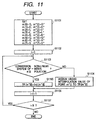
- Fig. 11 is a flow chart showing the processing procedure of the representative-point conversion unit.
- S1101 handles eight pixels of sample points as variables of m[] and eight pixels of the set representative points as variables of m''[] in initialization in order to simplify description.
- S1103 judges whether the conversion system of a sample point m[i] conforms to non-linear interpolation. That is, in the case of the present embodiment, it is necessary to previously determine a conversion system of an adjacent pixel to be scanned after a noticeable pixel.
- a linear interpolation value at a representative point is calculated in S1104 to assign the calculated linear interpolation value to a conversion value (assumed as TR).
- a conversion value of a representative point is calculated not through a conversion system selected for a noticeable pixel but through nonlinear conversion of adjacent circumferential pixels.
- the processing system for linear interpolation is not changed but sample points used for calculation are changed: That is, the linear interpolation A performs linear interpolation by using the sample point of original information but the linear interpolation B performs linear interpolation in accordance with a conversion value of a representative point. That is, calculations for linear interpolation are performed in accordance with eight conversion values such as TR[G''], TR[H''], TR[I''], TR[L''], TR[N''], TR[Q''], TR[R''] and TR[S"] and a pixel value of M serving as a noticeable pixel.
- conversion values of interpolation points of a to p about the noticeable pixel are calculated.
- Numeral 1303 denotes a calculation unit for calculating interpolation values in accordance with the interpolation information for linear interpolation, maximum/minimum information (above-described MAX5, MIN5, MAX3 and MIN3 in the case of the present embodiment) in a window sent from maximum/minimum value detection means and sum-of-products coefficient sent from the selection unit.
- maximum/minimum information above-described MAX5, MIN5, MAX3 and MIN3 in the case of the present embodiment
- the calculation unit calculates an interpolation value OUT[i][j] at an interpolation point (i,j) through the following calculations.
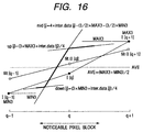
- Fig. 16 shows a case of using a filter for the adaptive LPF unit.
- a point indicated by a white-circle mark shows a pixel value after conversion using an adaptive LPF.
- an observation pixel according to the first window is also shown in Fig. 16 to show a relative positional relation with a conversion value.
- an edge position is slightly different from the case of using the first window. A shift of the edge position is very effective to reduce jaggies.
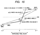
- Figs. 15 and 16 respectively describes a case in which I[q-1] is MIN3 and I[q+1] is MAX in order to simply the description. It is a matter of course that the present embodiment makes it possible to realize preferable nonlinear interpolation in any case.
- the sum-of-products calculation between the linear interpolation unit and a representative value in the window is described in the form of the expression (4) in order to simply the description.
- linear interpolation is effectuated by the sum-of-products calculation
- Nonlinear interpolation is effectuated by the following thought. That is, to remove an input resolution dependent part from input video information, adaptive smoothing for cutting high-frequency components of input resolution is necessary. However, even if only already-passing low-frequency components are output, an image having only remarkable halation is obtained. Therefore, nonlinear interpolation is indispensable that generates a high-frequency component corresponding to an output resolution.
- An object of the present invention is how to keep the continuity of converted pixel values when performing adaptive interpolation conversion every pixel.
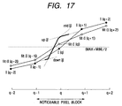
- Figs. 17, 18 and 19 are described below.
- Fig. 17 shows a case of using the pixel value information of the first window formation unit, in which the abscissa shows spatial coordinate and the longitudinal direction shows density.
- an observation pixel value becomes I[q] shown by a black-circle mark (pixel values of spatially front and rear sample points are assumed as I[q-2], I[q-1], I[q], I[q+1] and I[q+2]).
- the noticeable pixel is analogously shown using an interpolation range when converting the noticeable pixel as a noticeable-pixel block.
- the locus shown by a thick line serves as an output OUT[j] of the noticeable pixel depending on the relation between sizes of the above described three loci up[j], down[j] and mid[j].
- Fig. 18 shows loci of conversion values according to the conventional example (Japanese Patent Application Laid-Open No. 10-248012) when points q-1 and q+1 serving as spatially front and rear pixels are linearly interpolated in addition to the loci in Fig. 17.
- the interpolation range of each sample point is hereafter referred to as a conversion pixel block. That is, a discontinuous distortion occurs when conversion pixel blocks are changed.
- boundary points of conversion pixel blocks are midpoints between sample points q and q-1 and between sample points q and q+1.
- Fig. 19 shows loci of conversion values when using the structure of the present embodiment in Fig. 1. That is, when a point q-1 is a noticeable pixel, the conversion system uses linear interpolation. Moreover, because the conversion system of an adjacent pixel (corresponding to a point q in this case) uses nonlinear interpolation, a nonlinear interpolation value of the boundary point (shown by a white-square mark) of a conversion pixel serving as the midpoint between points q and q+1 is calculated to calculate linear interpolation in accordance with a conversion value of the nonlinear interpolation value.
- a nonlinear interpolation value of the boundary point (shown by a white-square mark) of a conversion pixel block serving as the midpoint between the points q and q+1 is calculated to calculate linear interpolation in accordance with a conversion value of the nonlinear interpolation value.
- the thought of the present invention is nonlinear interpolation + dynamic interpolation.
- dynamic interpolation represents that interpolation to be calculated in accordance with a sample point and interpolation to be calculated in accordance with a conversion value of a set representative point are dynamically switched.
- dynamic interpolation represents that positions of a representative point used for interpolation calculation are dynamically changed.
- a combination between conversion systems of a noticeable pixel and an adjacent pixel controls a dynamic change. Because conversion systems are sequenced, conversion according to priority can be made even at a boundary point.
- dynamic interpolation is described as nonlinear interpolation + dynamic linear interpolation by using linear interpolation as an example.
- nonlinear interpolation + dynamic nonlinear interpolation is also considered. In this case, it is preferable to sequence several priorities even in nonlinear interpolation.
- an image processing apparatus of the present invention it is permitted to use not only an integrally or separately set unit serving as an image output terminal of an information processor such as a computer but also a copying machine combined with a reader or a facsimile system having a transmission/reception function.
- the present invention can be applied to a system constituted of a plurality of devices such as a host computer, interface unit, reader and printer. Furthermore, the present invention can be applied to a single device such as a copying machine or facsimile device.
- the present invention can be applied to the case in which a storage medium storing a program code of software for realizing the function of the above embodiment is supplied to a system or apparatus and the computer (or CPU or MPU) of the system or apparatus reads and executes the program code stored in the storage medium.
- the program code read out of the storage medium constitutes the function of the above embodiment and the storage medium storing the program code constitutes the present invention.
- the storage medium for supplying a program code can use one of a floppy disk, hard disk, optical disk, magnetooptical disk, CR-ROM, CR-R, magnetic tape, nonvolatile memory card and ROM.
- An aspect of the present invention thus provides a storage medium storing processor implementable instructions for controlling a processor to carry out the method as hereinbefore described.
- the computer program can be obtained in electronic form for example by downloading the code over a network such as the internet.
- an electrical signal carrying processor implementable instructions for controlling a processor to carry out the method as hereinbefore described.
Landscapes
- Physics & Mathematics (AREA)
- General Physics & Mathematics (AREA)
- Engineering & Computer Science (AREA)
- Theoretical Computer Science (AREA)
- Image Processing (AREA)
- Editing Of Facsimile Originals (AREA)
Applications Claiming Priority (2)
| Application Number | Priority Date | Filing Date | Title |
|---|---|---|---|
| JP14491799A JP3167120B2 (ja) | 1999-05-25 | 1999-05-25 | 画像処理装置及び方法 |
| JP14491799 | 1999-05-25 |
Publications (3)
| Publication Number | Publication Date |
|---|---|
| EP1056045A2 true EP1056045A2 (fr) | 2000-11-29 |
| EP1056045A3 EP1056045A3 (fr) | 2005-12-21 |
| EP1056045B1 EP1056045B1 (fr) | 2008-09-10 |
Family
ID=15373258
Family Applications (1)
| Application Number | Title | Priority Date | Filing Date |
|---|---|---|---|
| EP00304294A Expired - Lifetime EP1056045B1 (fr) | 1999-05-25 | 2000-05-22 | Procédé et appareil de changement adaptatif de résolution d'une image numérique |
Country Status (4)
| Country | Link |
|---|---|
| US (1) | US6714693B1 (fr) |
| EP (1) | EP1056045B1 (fr) |
| JP (1) | JP3167120B2 (fr) |
| DE (1) | DE60040186D1 (fr) |
Cited By (1)
| Publication number | Priority date | Publication date | Assignee | Title |
|---|---|---|---|---|
| GB2514410A (en) * | 2013-05-24 | 2014-11-26 | Ibm | Image scaling for images including low resolution text |
Families Citing this family (17)
| Publication number | Priority date | Publication date | Assignee | Title |
|---|---|---|---|---|
| JP4617825B2 (ja) * | 2003-10-22 | 2011-01-26 | ソニー株式会社 | データ処理装置およびデータ処理方法、プログラム、並びに記録媒体 |
| KR100530224B1 (ko) * | 2004-04-20 | 2005-11-22 | 삼성전자주식회사 | 이미지 변환 장치 및 그 방법 |
| US7668366B2 (en) | 2005-08-09 | 2010-02-23 | Seiko Epson Corporation | Mosaic image data processing |
| RU2006131031A (ru) | 2006-08-29 | 2008-03-10 | Самсунг Электроникс Ко., Лтд. (KR) | Способ и устройство увеличения разрешения изображения |
| JP2008234426A (ja) * | 2007-03-22 | 2008-10-02 | Seiko Epson Corp | 画像処理方法、画像処理装置及び電子機器 |
| US8934713B2 (en) * | 2007-06-25 | 2015-01-13 | Intel Corporation | Image processing device, image processing method, program, and imaging device |
| US8233748B2 (en) * | 2007-07-20 | 2012-07-31 | Samsung Electronics Co., Ltd. | Image-resolution-improvement apparatus and method |
| JP4874904B2 (ja) * | 2007-09-13 | 2012-02-15 | 株式会社東芝 | 画像処理装置及びその方法 |
| EP2229658A1 (fr) * | 2007-12-21 | 2010-09-22 | Dolby Laboratories Licensing Corporation | Traitement d'image guidé par la bordure |
| EP2249308B1 (fr) * | 2008-03-03 | 2014-12-17 | Mitsubishi Electric Corporation | Dispositif et procédé de traitement d'image, et dispositif et procédé d'affichage d'image |
| WO2009149601A1 (fr) * | 2008-06-13 | 2009-12-17 | Shanghai Hewlett-Packard Co., Ltd | Traitement d’une image cible à superrésolution |
| JP5115361B2 (ja) * | 2008-06-27 | 2013-01-09 | 富士通株式会社 | 画素補間装置、画素補間方法および画素補間プログラム |
| JP4504449B2 (ja) * | 2008-11-28 | 2010-07-14 | 株式会社東芝 | 情報処理装置およびプログラム |
| KR20110021488A (ko) * | 2009-08-26 | 2011-03-04 | 삼성전자주식회사 | 영상의 선명도를 향상시키는 디스플레이 장치 및 영상 처리 방법 |
| JP5366855B2 (ja) * | 2010-02-16 | 2013-12-11 | 富士フイルム株式会社 | 画像処理方法及び装置並びにプログラム |
| JP2012186769A (ja) * | 2011-03-08 | 2012-09-27 | Fuji Xerox Co Ltd | 画像処理装置及びプログラム |
| JP5863554B2 (ja) | 2012-05-01 | 2016-02-16 | 国立大学法人旭川医科大学 | 画像処理装置、画像処理方法、およびプログラム |
Family Cites Families (16)
| Publication number | Priority date | Publication date | Assignee | Title |
|---|---|---|---|---|
| US4803558A (en) | 1985-11-15 | 1989-02-07 | Konishiroku Photo Industry Co., Ltd. | Halftone image estimation methods for dither images |
| JPS62200976A (ja) * | 1986-02-28 | 1987-09-04 | Dainippon Screen Mfg Co Ltd | 高分解能2値化画像出力装置 |
| US5008752A (en) * | 1989-06-16 | 1991-04-16 | Eastman Kodak Company | Digital image interpolator with multiple interpolation algorithms |
| US5054100A (en) * | 1989-11-16 | 1991-10-01 | Eastman Kodak Company | Pixel interpolator with edge sharpening |
| US5410615A (en) * | 1990-09-25 | 1995-04-25 | Xerox Corporation | Bitmap image resolution converter compensating for write-white xerographic laser printing |
| JP2991485B2 (ja) | 1990-11-29 | 1999-12-20 | 株式会社東芝 | 画像処理装置 |
| US5430811A (en) * | 1991-12-25 | 1995-07-04 | Matsushita Electric Industrial Co., Ltd. | Method for interpolating missing pixels and an apparatus employing the method |
| US5363213A (en) * | 1992-06-08 | 1994-11-08 | Xerox Corporation | Unquantized resolution conversion of bitmap images using error diffusion |
| DE69432093T2 (de) | 1993-09-27 | 2003-07-17 | Canon Kk | Bildverarbeitungsvorrichtung |
| JP3176195B2 (ja) | 1993-10-28 | 2001-06-11 | キヤノン株式会社 | 画像処理装置 |
| JP3195142B2 (ja) | 1993-10-29 | 2001-08-06 | キヤノン株式会社 | 画像処理方法及び装置 |
| EP0753828B1 (fr) * | 1995-07-13 | 2002-10-02 | Fuji Photo Film Co., Ltd. | Procédé et appareil pour l'interpolation des signaux d'images |
| JP3200351B2 (ja) | 1996-03-14 | 2001-08-20 | キヤノン株式会社 | 画像処理装置及びその方法 |
| US5917963A (en) | 1995-09-21 | 1999-06-29 | Canon Kabushiki Kaisha | Image processing apparatus and image processing method |
| US6157749A (en) * | 1997-03-05 | 2000-12-05 | Canon Kabushiki Kaisha | Image processing apparatus and method, and storing medium |
| JP3210264B2 (ja) | 1997-03-05 | 2001-09-17 | キヤノン株式会社 | 画像処理装置及び方法 |
-
1999
- 1999-05-25 JP JP14491799A patent/JP3167120B2/ja not_active Expired - Fee Related
-
2000
- 2000-05-22 DE DE60040186T patent/DE60040186D1/de not_active Expired - Lifetime
- 2000-05-22 EP EP00304294A patent/EP1056045B1/fr not_active Expired - Lifetime
- 2000-05-22 US US09/575,243 patent/US6714693B1/en not_active Expired - Fee Related
Cited By (1)
| Publication number | Priority date | Publication date | Assignee | Title |
|---|---|---|---|---|
| GB2514410A (en) * | 2013-05-24 | 2014-11-26 | Ibm | Image scaling for images including low resolution text |
Also Published As
| Publication number | Publication date |
|---|---|
| EP1056045B1 (fr) | 2008-09-10 |
| DE60040186D1 (de) | 2008-10-23 |
| JP3167120B2 (ja) | 2001-05-21 |
| JP2000339449A (ja) | 2000-12-08 |
| EP1056045A3 (fr) | 2005-12-21 |
| US6714693B1 (en) | 2004-03-30 |
Similar Documents
| Publication | Publication Date | Title |
|---|---|---|
| EP1056045B1 (fr) | Procédé et appareil de changement adaptatif de résolution d'une image numérique | |
| EP0863484B1 (fr) | Méthode et appareil de traitement d'image | |
| JP3143209B2 (ja) | 画像変倍装置 | |
| EP0645736B1 (fr) | Appareil de traitement d'images | |
| US5917963A (en) | Image processing apparatus and image processing method | |
| EP0803841B1 (fr) | Procédé et dispositif de traitement d'images | |
| EP0650287B1 (fr) | Procédé et appareil de traitement d'images | |
| EP0949585B1 (fr) | Dispositif et méthode pour interpoler des données d'image | |
| JP2004040790A (ja) | 画像信号のデ・スクリーン方法及びシステム | |
| JP2973899B2 (ja) | 画像処理装置 | |
| JP3176195B2 (ja) | 画像処理装置 | |
| US6400413B1 (en) | Image process apparatus, image process method and computer-readable storage medium | |
| US6289136B1 (en) | Image processing method and apparatus | |
| JP3210264B2 (ja) | 画像処理装置及び方法 | |
| JP3026706B2 (ja) | 画像処理装置 | |
| JP3092769B2 (ja) | 画像処理装置 | |
| JP3200351B2 (ja) | 画像処理装置及びその方法 | |
| JP3624153B2 (ja) | 画像処理装置及び画像処理方法 | |
| JP3262425B2 (ja) | 画像処理装置 | |
| JP3059287B2 (ja) | 2値画像変倍装置 | |
| JP3949642B2 (ja) | 画像処理装置 | |
| JPH09130597A (ja) | 画像処理方法とその装置 | |
| JP3054338B2 (ja) | 画像処理装置およびその方法 | |
| JP2878695B2 (ja) | 画像処理装置および多値画像推定方法 | |
| JP2004096715A (ja) | 画像データ補間装置、画像データ補間処理用コンピュータ、画像データ補間方法および画像データ補間プログラムを記録した媒体 |
Legal Events
| Date | Code | Title | Description |
|---|---|---|---|
| PUAI | Public reference made under article 153(3) epc to a published international application that has entered the european phase |
Free format text: ORIGINAL CODE: 0009012 |
|
| AK | Designated contracting states |
Kind code of ref document: A2 Designated state(s): AT BE CH CY DE DK ES FI FR GB GR IE IT LI LU MC NL PT SE |
|
| AX | Request for extension of the european patent |
Free format text: AL;LT;LV;MK;RO;SI |
|
| PUAL | Search report despatched |
Free format text: ORIGINAL CODE: 0009013 |
|
| AK | Designated contracting states |
Kind code of ref document: A3 Designated state(s): AT BE CH CY DE DK ES FI FR GB GR IE IT LI LU MC NL PT SE |
|
| AX | Request for extension of the european patent |
Extension state: AL LT LV MK RO SI |
|
| 17P | Request for examination filed |
Effective date: 20060621 |
|
| AKX | Designation fees paid |
Designated state(s): DE FR GB IT |
|
| 17Q | First examination report despatched |
Effective date: 20060823 |
|
| GRAP | Despatch of communication of intention to grant a patent |
Free format text: ORIGINAL CODE: EPIDOSNIGR1 |
|
| GRAS | Grant fee paid |
Free format text: ORIGINAL CODE: EPIDOSNIGR3 |
|
| GRAA | (expected) grant |
Free format text: ORIGINAL CODE: 0009210 |
|
| AK | Designated contracting states |
Kind code of ref document: B1 Designated state(s): DE FR GB IT |
|
| REG | Reference to a national code |
Ref country code: GB Ref legal event code: FG4D |
|
| REF | Corresponds to: |
Ref document number: 60040186 Country of ref document: DE Date of ref document: 20081023 Kind code of ref document: P |
|
| PLBE | No opposition filed within time limit |
Free format text: ORIGINAL CODE: 0009261 |
|
| STAA | Information on the status of an ep patent application or granted ep patent |
Free format text: STATUS: NO OPPOSITION FILED WITHIN TIME LIMIT |
|
| 26N | No opposition filed |
Effective date: 20090611 |
|
| PGFP | Annual fee paid to national office [announced via postgrant information from national office to epo] |
Ref country code: FR Payment date: 20130621 Year of fee payment: 14 Ref country code: IT Payment date: 20130507 Year of fee payment: 14 |
|
| REG | Reference to a national code |
Ref country code: FR Ref legal event code: ST Effective date: 20150130 |
|
| PG25 | Lapsed in a contracting state [announced via postgrant information from national office to epo] |
Ref country code: IT Free format text: LAPSE BECAUSE OF NON-PAYMENT OF DUE FEES Effective date: 20140522 |
|
| PG25 | Lapsed in a contracting state [announced via postgrant information from national office to epo] |
Ref country code: FR Free format text: LAPSE BECAUSE OF NON-PAYMENT OF DUE FEES Effective date: 20140602 |
|
| PGFP | Annual fee paid to national office [announced via postgrant information from national office to epo] |
Ref country code: GB Payment date: 20150528 Year of fee payment: 16 Ref country code: DE Payment date: 20150531 Year of fee payment: 16 |
|
| REG | Reference to a national code |
Ref country code: DE Ref legal event code: R119 Ref document number: 60040186 Country of ref document: DE |
|
| GBPC | Gb: european patent ceased through non-payment of renewal fee |
Effective date: 20160522 |
|
| PG25 | Lapsed in a contracting state [announced via postgrant information from national office to epo] |
Ref country code: DE Free format text: LAPSE BECAUSE OF NON-PAYMENT OF DUE FEES Effective date: 20161201 |
|
| PG25 | Lapsed in a contracting state [announced via postgrant information from national office to epo] |
Ref country code: GB Free format text: LAPSE BECAUSE OF NON-PAYMENT OF DUE FEES Effective date: 20160522 |