EP1056165A2 - Bloc répartiteur pour connecter des actionneurs ou des capteurs - Google Patents
Bloc répartiteur pour connecter des actionneurs ou des capteurs Download PDFInfo
- Publication number
- EP1056165A2 EP1056165A2 EP00110405A EP00110405A EP1056165A2 EP 1056165 A2 EP1056165 A2 EP 1056165A2 EP 00110405 A EP00110405 A EP 00110405A EP 00110405 A EP00110405 A EP 00110405A EP 1056165 A2 EP1056165 A2 EP 1056165A2
- Authority
- EP
- European Patent Office
- Prior art keywords
- connection
- distributor
- distributor according
- sensors
- actuators
- Prior art date
- Legal status (The legal status is an assumption and is not a legal conclusion. Google has not performed a legal analysis and makes no representation as to the accuracy of the status listed.)
- Granted
Links
Images


Classifications
-
- H—ELECTRICITY
- H05—ELECTRIC TECHNIQUES NOT OTHERWISE PROVIDED FOR
- H05K—PRINTED CIRCUITS; CASINGS OR CONSTRUCTIONAL DETAILS OF ELECTRIC APPARATUS; MANUFACTURE OF ASSEMBLAGES OF ELECTRICAL COMPONENTS
- H05K7/00—Constructional details common to different types of electric apparatus
- H05K7/14—Mounting supporting structure in casing or on frame or rack
- H05K7/1462—Mounting supporting structure in casing or on frame or rack for programmable logic controllers [PLC] for automation or industrial process control
- H05K7/1468—Mechanical features of input/output (I/O) modules
- H05K7/1472—Bus coupling modules, e.g. bus distribution modules
-
- H—ELECTRICITY
- H01—ELECTRIC ELEMENTS
- H01R—ELECTRICALLY-CONDUCTIVE CONNECTIONS; STRUCTURAL ASSOCIATIONS OF A PLURALITY OF MUTUALLY-INSULATED ELECTRICAL CONNECTING ELEMENTS; COUPLING DEVICES; CURRENT COLLECTORS
- H01R25/00—Coupling parts adapted for simultaneous co-operation with two or more identical counterparts, e.g. for distributing energy to two or more circuits
- H01R25/003—Coupling parts adapted for simultaneous co-operation with two or more identical counterparts, e.g. for distributing energy to two or more circuits the coupling part being secured only to wires or cables
Definitions
- the invention relates to an active or passive distributor for connecting Actuators and / or sensors with at least one external electrical device, in particular with a control unit such as a PC or a PLC
- the Distributor has the following: a first connection area for connecting the Actuators and / or sensors on the distributor, and one on the first Connection area adjacent second connection area for connection at least a connecting cable for the supply of the actuators and / or sensors and / or for forwarding the actuator / sensor signals between the actuators / sensors and the electrical device.
- a distributor of the generic type is known from EP 0 909 121 A2.
- the distributors known from this document have the disadvantage that an increase in Number of connections for the actuators or sensors based on the selected one Arrangement of the connections also a significant increase in the space of the Distributor conditionally because the connections on one of the outer surfaces of the distributor are tight lie together.
- the first connection area can indeed be used to connect the actuators and sensors can be rotated by 90 °, which makes it possible to connect the actuators and attach sensors from two directions that are 90 ° apart. Nevertheless, the possibility of rotating the connection area does not cause any Possibility to increase the connection density or the maximum possible number of Connections on the connection area or connection block. This is because difficult handling of the module in an unacceptable manner would if the plug connections were simply moved closer together.
- Another problem of the generic state is that none satisfactory solution to the task was found, the junction box for the cable to the electrical device easily to various installation and To be able to adjust alignment requirements.
- the invention therefore aims to provide a distributor that is small Space requirements with a large number of easily accessible connections is predictable.
- the at least one first connection area is designed as a connection block with a plurality of connection segments oriented at an angle to one another, on which the connections for the actuators or sensors are arranged at least partially at an angle to one another.
- the connecting segments are particularly preferably aligned at an obtuse angle to one another.
- connection segments also enable the easy attachment of Markings or displays (e.g. light emitting diodes) on the surfaces of the Connection segments, especially if the segments are obtuse to each other are aligned so that the surface available for the connections the terminal block significantly increased compared to a single rectangular area becomes.
- Markings or displays e.g. light emitting diodes
- connection segments A particularly good handling of the distributor is guaranteed when on each of the connection segments only one of the connections or only one Row of adjacent connectors is arranged.
- the terminal block will preferably divided into as many segments as possible, since handling the the plug to be inserted into the connections the easier the larger the angle are between the individual plugs.
- Preferably close Connection segments each with an angle of approximately 30 to 60 °, preferably 45 ° the base of the connection block.
- connection housing of the invention has a cable feed or implementation - preferably designed as a tubular extension - for Lead the connection cable into the interior of the connection housing, which on Connection housing is arranged movably. Due to the moveable arrangement it is no longer required for different orientations of the connection cable to produce different types of housings. It is also no longer necessary that Relocate the connector housing relative to the connector block.
- the (tube-like) attachment is on the connection housing guided on a circular arc section.
- This variant of the The invention is particularly suitable for a distributor whose connection housing with two or more connection blocks is provided.
- the pivotability of the Approach enables alignment in a circular arc section of e.g. 90 ° and more and thus the accessibility of two of the housing sides without attached terminal block.
- connection housing several mutually rotatable sections, so that the Orientation of the tubular extension relative to the base of the distributor is multiple adjustable. Due to the multiple adjustability, the tubular Approach in almost any angular position, so that the Distributor can be optimally adapted to any installation situation.
- This external device can be a control unit, for example be like a PC or a PLC.
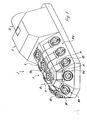
- the distributor 2 has a first designed as a connection block 4 Connection area for connecting the actuators and / or sensors to the distributor 2 as well as a connection housing 6 directly attached to the connection block 4 as Connection area for connecting at least one (also not shown here) Connection cable for the supply of the actuators and / or sensors and / or Forwarding the actuator / sensor signals to and from the electrical device.
- connection block 4 is provided with a plurality of connection segments 8a, 8b, 8c, ... aligned at an angle to one another, on which the connections 10 (for example using M8 or M10 technology) for the actuators or sensors are arranged.
- the connection block 4 of the distributor has a connection-free - in the installation position of FIG. 1 lower "base surface, to which the first connection segment 8a is aligned parallel.
- connection segments 8b, 8c lie at an acute angle to the base surface and at an obtuse angle to the first connection segment 8a, so that the connection block 4 is essentially trapezoidal in one of its cross sections
- Three of the connections 10 are each arranged in a row next to one another on each of the three connection segments 8a-8c described above, and three further connection segments 8d, 8e, 8f are molded onto the axial end of the elongated connection block 4 facing away from the connection housing 6 include an obtuse angle and an acute angle with the base, which are provided with only one of the connections 10 and which axially terminate the connection block 4 essentially tapering.
- connection 10 of the connection segments 8 of the connection block 4 is extremely accessible.
- By arranging the connections 10 to each other obtuse-angled connecting segments 8 will also have a high density of Connections 10 realized in a confined space, which is possible because of the connector are aligned at an angle to each other and thus at least to theirs Connected ends are not as close together as this in one single connection level would be the case.
- the connectors in the arrangement of the plug in only one level almost not more manageable.
- the obtuse angled direction of the Connection segments 8 to each other due to the particularly large surface area of the Terminal block 4 an easy attachment of labeling fields K and Display diodes A.
- connection housing 6 which has a substantially trapezoidal cross section and a Housing opening for passing the at least one to the electrical device leading connection cable for the supply of the actuators and / or sensors has to which a tubular extension 12 for passing the connecting cable is molded into the interior of the connector housing with plug connector.
- the housing 6 can optionally serve to accommodate electronics, not shown here (active distributor).
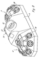
- Fig. 2 differs from the version of Fig. 1 in that the distributor with removed connector housing is shown. You can see them Connector 14 for connecting the external cable.
- FIG. 3 corresponds in terms of its principle Function of the embodiment of FIGS. 1 and 2, but are Connection segments 8a, 8b and 8c each with only a single connection 10 Mistake.
- This distributor is particularly compact, with the connections 10 is arranged at an angle to each other, so that particularly good accessibility all connections are guaranteed.
- FIG. 4 corresponds in terms of the structure of the Terminal block the embodiment of Fig. 3.
- Fig. 4 selected a solution in which the tubular extension 12 on the electronics housing 6 is pivotally arranged.
- the tubular extension 12 is of a kind Hemispherical shell 16 arranged on a cylindrical housing section 18th (is rotated by almost 360 °) 18.
- the housing section 18 is again provided with a projection 20 which has a substantially flat base has, which bears on the flat outer surface of the terminal block 4 and on this is rotatably mounted.
- connection block 6 corresponds to the construction of the first connection block 4 Embodiment of FIG. 3. Unlike in FIG. 3, however, the first terminal block opposite end of the connection and / or Electronics housing 6 a second terminal block 4 'attached, the structure of the corresponds to the first connection block 4.
- the tubular approach 12 of the Electronics housing 6 points vertically upwards, other orientations of the tubular approach can also be realized (in the manufacture).
- This Distributor 2 with two connection blocks realizes a particularly high one Connection density with small dimensions and excellent manageability.
- a simple, needs-oriented alignment of the tubular extension 12 To enable the distributor with two connection blocks, this is after the 7 and 8 arranged on a sliding element 22, which has an arc shape and in an arcuate recess 24 (with Guide elements (not shown here) for the sliding element 22) can be pivoted.
Landscapes
- Engineering & Computer Science (AREA)
- Automation & Control Theory (AREA)
- Microelectronics & Electronic Packaging (AREA)
- Air Bags (AREA)
- Power Steering Mechanism (AREA)
- Vehicle Body Suspensions (AREA)
- Connector Housings Or Holding Contact Members (AREA)
- Connection Or Junction Boxes (AREA)
- Motor Or Generator Frames (AREA)
- Details Of Connecting Devices For Male And Female Coupling (AREA)
- Actuator (AREA)
- Connections Arranged To Contact A Plurality Of Conductors (AREA)
Applications Claiming Priority (4)
| Application Number | Priority Date | Filing Date | Title |
|---|---|---|---|
| DE29909204U DE29909204U1 (de) | 1999-05-28 | 1999-05-28 | Verteiler zum Verbinden von Aktoren und/oder Sensoren |
| DE29909204U | 1999-05-28 | ||
| DE29909205U | 1999-05-28 | ||
| DE29909205U DE29909205U1 (de) | 1999-05-28 | 1999-05-28 | Verteiler zum Verbinden von Aktoren und/oder Sensoren |
Publications (3)
| Publication Number | Publication Date |
|---|---|
| EP1056165A2 true EP1056165A2 (fr) | 2000-11-29 |
| EP1056165A3 EP1056165A3 (fr) | 2001-05-02 |
| EP1056165B1 EP1056165B1 (fr) | 2007-04-25 |
Family
ID=26062528
Family Applications (1)
| Application Number | Title | Priority Date | Filing Date |
|---|---|---|---|
| EP00110405A Expired - Lifetime EP1056165B1 (fr) | 1999-05-28 | 2000-05-16 | Bloc répartiteur pour connecter des actionneurs ou des capteurs |
Country Status (4)
| Country | Link |
|---|---|
| EP (1) | EP1056165B1 (fr) |
| AT (1) | ATE360902T1 (fr) |
| DE (1) | DE50014273D1 (fr) |
| ES (1) | ES2285981T3 (fr) |
Cited By (2)
| Publication number | Priority date | Publication date | Assignee | Title |
|---|---|---|---|---|
| EP1244184A3 (fr) * | 2001-03-23 | 2004-01-07 | GWT Global Weighing Technologies GmbH | Système de connexion pour connecter des cellules de pesage |
| DE102009044990B4 (de) | 2009-09-24 | 2019-09-12 | Ifm Electronic Gmbh | Interface-Modul zum Anschluss eines Feldgeräts |
Families Citing this family (1)
| Publication number | Priority date | Publication date | Assignee | Title |
|---|---|---|---|---|
| DE102010062837B3 (de) * | 2010-12-10 | 2012-05-10 | Ifm Electronic Gmbh | Interface-Modul zum Anschluss mindestens eines Feldgeräts an eine Busleitung |
Family Cites Families (4)
| Publication number | Priority date | Publication date | Assignee | Title |
|---|---|---|---|---|
| DE4412270C2 (de) * | 1994-04-09 | 1996-02-01 | Murrelektronik Ag | Bus-System |
| DE4437316C2 (de) * | 1994-10-19 | 2001-12-20 | Bosch Gmbh Robert | Dezentrale Ein/Ausgabebaugruppe für elektronische Steuerungen |
| DE19716137C1 (de) * | 1997-04-17 | 1998-10-22 | Siemens Ag | Modul zum Anschluß von Aktoren und/oder Sensoren |
| DE19743972A1 (de) * | 1997-10-06 | 1999-04-29 | Phoenix Contact Gmbh & Co | Elektronisches Ein-/Ausgabemodul |
-
2000
- 2000-05-16 EP EP00110405A patent/EP1056165B1/fr not_active Expired - Lifetime
- 2000-05-16 DE DE50014273T patent/DE50014273D1/de not_active Expired - Lifetime
- 2000-05-16 ES ES00110405T patent/ES2285981T3/es not_active Expired - Lifetime
- 2000-05-16 AT AT00110405T patent/ATE360902T1/de active
Cited By (2)
| Publication number | Priority date | Publication date | Assignee | Title |
|---|---|---|---|---|
| EP1244184A3 (fr) * | 2001-03-23 | 2004-01-07 | GWT Global Weighing Technologies GmbH | Système de connexion pour connecter des cellules de pesage |
| DE102009044990B4 (de) | 2009-09-24 | 2019-09-12 | Ifm Electronic Gmbh | Interface-Modul zum Anschluss eines Feldgeräts |
Also Published As
| Publication number | Publication date |
|---|---|
| ES2285981T3 (es) | 2007-12-01 |
| EP1056165A3 (fr) | 2001-05-02 |
| EP1056165B1 (fr) | 2007-04-25 |
| DE50014273D1 (de) | 2007-06-06 |
| ATE360902T1 (de) | 2007-05-15 |
Similar Documents
| Publication | Publication Date | Title |
|---|---|---|
| EP3033808B1 (fr) | Trame pour connecteurs | |
| EP2783433B1 (fr) | Connecteur avec blindage | |
| EP3766136A1 (fr) | Connecteur de cartes de circuits imprimés | |
| DE102009015542A1 (de) | Bidirektionale Kabelschuhverbindung und Verfahren | |
| DE69301975T2 (de) | Elektrischer Verbinder für gedruckte Leiterplatten | |
| EP3796482A1 (fr) | Connecteur enfichable comprenant un pont conducteur de protection | |
| EP3981046B1 (fr) | Connecteur de carte de circuit imprimé modulaire | |
| DE29521213U1 (de) | Steckverbindersystem | |
| DE3708902A1 (de) | Steuereinheit fuer elektrohydraulische ausbausteuerungen | |
| DE60000853T2 (de) | Verbinder mit überbrückbaren und konfigurierbaren Kontakten | |
| EP1056165B1 (fr) | Bloc répartiteur pour connecter des actionneurs ou des capteurs | |
| EP3396655A1 (fr) | Panneau led | |
| DE29909205U1 (de) | Verteiler zum Verbinden von Aktoren und/oder Sensoren | |
| EP3891849A1 (fr) | Boîtier d'adaptateur pour un élément de contact destiné à la fixation sur un profilé chapeau | |
| EP3923419A1 (fr) | Système de connecteur enfichable modulaire | |
| DE29909204U1 (de) | Verteiler zum Verbinden von Aktoren und/oder Sensoren | |
| EP3769372A1 (fr) | Support de contact modulaire pour connecteur enfichable industriel | |
| EP1381118A1 (fr) | Connecteur symétrique | |
| DE212020000795U1 (de) | Kontaktmodul | |
| DE102016101629A1 (de) | Linearbewegliches Gleitkontaktelement mit Transportvorrichtung und Verfahren zur Herstellung | |
| EP0735627B1 (fr) | Répartiteur électrique enfichable | |
| DE20019792U1 (de) | Steckverbinder-Gehäuse mit Kodiereinrichtung | |
| EP0794592A2 (fr) | Distributeur en forme d'un peigne avec une borne de connexion | |
| DE29919900U1 (de) | Verteilersystem | |
| DE19721556C2 (de) | Profilgestellrahmen |
Legal Events
| Date | Code | Title | Description |
|---|---|---|---|
| PUAI | Public reference made under article 153(3) epc to a published international application that has entered the european phase |
Free format text: ORIGINAL CODE: 0009012 |
|
| AK | Designated contracting states |
Kind code of ref document: A2 Designated state(s): AT BE CH CY DE DK ES FI FR GB GR IE IT LI LU MC NL PT SE |
|
| AX | Request for extension of the european patent |
Free format text: AL;LT;LV;MK;RO;SI |
|
| PUAL | Search report despatched |
Free format text: ORIGINAL CODE: 0009013 |
|
| AK | Designated contracting states |
Kind code of ref document: A3 Designated state(s): AT BE CH CY DE DK ES FI FR GB GR IE IT LI LU MC NL PT SE |
|
| AX | Request for extension of the european patent |
Free format text: AL;LT;LV;MK;RO;SI |
|
| 17P | Request for examination filed |
Effective date: 20010522 |
|
| AKX | Designation fees paid |
Free format text: AT BE CH CY DE DK ES FI FR GB GR IE IT LI LU MC NL PT SE |
|
| GRAP | Despatch of communication of intention to grant a patent |
Free format text: ORIGINAL CODE: EPIDOSNIGR1 |
|
| GRAS | Grant fee paid |
Free format text: ORIGINAL CODE: EPIDOSNIGR3 |
|
| GRAA | (expected) grant |
Free format text: ORIGINAL CODE: 0009210 |
|
| AK | Designated contracting states |
Kind code of ref document: B1 Designated state(s): AT BE CH CY DE DK ES FI FR GB GR IE IT LI LU MC NL PT SE |
|
| PG25 | Lapsed in a contracting state [announced via postgrant information from national office to epo] |
Ref country code: FI Free format text: LAPSE BECAUSE OF FAILURE TO SUBMIT A TRANSLATION OF THE DESCRIPTION OR TO PAY THE FEE WITHIN THE PRESCRIBED TIME-LIMIT Effective date: 20070425 |
|
| REG | Reference to a national code |
Ref country code: GB Ref legal event code: FG4D Free format text: NOT ENGLISH |
|
| REG | Reference to a national code |
Ref country code: IE Ref legal event code: FG4D Free format text: LANGUAGE OF EP DOCUMENT: GERMAN |
|
| REG | Reference to a national code |
Ref country code: CH Ref legal event code: EP |
|
| REF | Corresponds to: |
Ref document number: 50014273 Country of ref document: DE Date of ref document: 20070606 Kind code of ref document: P |
|
| REG | Reference to a national code |
Ref country code: SE Ref legal event code: TRGR |
|
| REG | Reference to a national code |
Ref country code: CH Ref legal event code: NV Representative=s name: ISLER & PEDRAZZINI AG |
|
| GBT | Gb: translation of ep patent filed (gb section 77(6)(a)/1977) |
Effective date: 20070718 |
|
| PG25 | Lapsed in a contracting state [announced via postgrant information from national office to epo] |
Ref country code: PT Free format text: LAPSE BECAUSE OF FAILURE TO SUBMIT A TRANSLATION OF THE DESCRIPTION OR TO PAY THE FEE WITHIN THE PRESCRIBED TIME-LIMIT Effective date: 20070925 |
|
| REG | Reference to a national code |
Ref country code: CH Ref legal event code: PCAR Free format text: ISLER & PEDRAZZINI AG;POSTFACH 1772;8027 ZUERICH (CH) |
|
| ET | Fr: translation filed | ||
| REG | Reference to a national code |
Ref country code: IE Ref legal event code: FD4D |
|
| REG | Reference to a national code |
Ref country code: ES Ref legal event code: FG2A Ref document number: 2285981 Country of ref document: ES Kind code of ref document: T3 |
|
| PG25 | Lapsed in a contracting state [announced via postgrant information from national office to epo] |
Ref country code: DK Free format text: LAPSE BECAUSE OF FAILURE TO SUBMIT A TRANSLATION OF THE DESCRIPTION OR TO PAY THE FEE WITHIN THE PRESCRIBED TIME-LIMIT Effective date: 20070425 Ref country code: MC Free format text: LAPSE BECAUSE OF NON-PAYMENT OF DUE FEES Effective date: 20070531 Ref country code: IE Free format text: LAPSE BECAUSE OF FAILURE TO SUBMIT A TRANSLATION OF THE DESCRIPTION OR TO PAY THE FEE WITHIN THE PRESCRIBED TIME-LIMIT Effective date: 20070425 |
|
| PLBE | No opposition filed within time limit |
Free format text: ORIGINAL CODE: 0009261 |
|
| STAA | Information on the status of an ep patent application or granted ep patent |
Free format text: STATUS: NO OPPOSITION FILED WITHIN TIME LIMIT |
|
| 26N | No opposition filed |
Effective date: 20080128 |
|
| PG25 | Lapsed in a contracting state [announced via postgrant information from national office to epo] |
Ref country code: GR Free format text: LAPSE BECAUSE OF FAILURE TO SUBMIT A TRANSLATION OF THE DESCRIPTION OR TO PAY THE FEE WITHIN THE PRESCRIBED TIME-LIMIT Effective date: 20070726 |
|
| PG25 | Lapsed in a contracting state [announced via postgrant information from national office to epo] |
Ref country code: CY Free format text: LAPSE BECAUSE OF FAILURE TO SUBMIT A TRANSLATION OF THE DESCRIPTION OR TO PAY THE FEE WITHIN THE PRESCRIBED TIME-LIMIT Effective date: 20070425 |
|
| PG25 | Lapsed in a contracting state [announced via postgrant information from national office to epo] |
Ref country code: LU Free format text: LAPSE BECAUSE OF NON-PAYMENT OF DUE FEES Effective date: 20070516 |
|
| REG | Reference to a national code |
Ref country code: FR Ref legal event code: PLFP Year of fee payment: 17 |
|
| REG | Reference to a national code |
Ref country code: FR Ref legal event code: PLFP Year of fee payment: 18 |
|
| REG | Reference to a national code |
Ref country code: FR Ref legal event code: PLFP Year of fee payment: 19 |
|
| PGFP | Annual fee paid to national office [announced via postgrant information from national office to epo] |
Ref country code: NL Payment date: 20190521 Year of fee payment: 20 |
|
| PGFP | Annual fee paid to national office [announced via postgrant information from national office to epo] |
Ref country code: IT Payment date: 20190527 Year of fee payment: 20 Ref country code: DE Payment date: 20190521 Year of fee payment: 20 Ref country code: ES Payment date: 20190620 Year of fee payment: 20 |
|
| PGFP | Annual fee paid to national office [announced via postgrant information from national office to epo] |
Ref country code: BE Payment date: 20190521 Year of fee payment: 20 Ref country code: FR Payment date: 20190522 Year of fee payment: 20 Ref country code: SE Payment date: 20190521 Year of fee payment: 20 |
|
| PGFP | Annual fee paid to national office [announced via postgrant information from national office to epo] |
Ref country code: CH Payment date: 20190521 Year of fee payment: 20 |
|
| PGFP | Annual fee paid to national office [announced via postgrant information from national office to epo] |
Ref country code: AT Payment date: 20190522 Year of fee payment: 20 Ref country code: GB Payment date: 20190521 Year of fee payment: 20 |
|
| REG | Reference to a national code |
Ref country code: DE Ref legal event code: R071 Ref document number: 50014273 Country of ref document: DE |
|
| REG | Reference to a national code |
Ref country code: NL Ref legal event code: MK Effective date: 20200515 |
|
| REG | Reference to a national code |
Ref country code: CH Ref legal event code: PL |
|
| REG | Reference to a national code |
Ref country code: GB Ref legal event code: PE20 Expiry date: 20200515 |
|
| REG | Reference to a national code |
Ref country code: SE Ref legal event code: EUG |
|
| REG | Reference to a national code |
Ref country code: BE Ref legal event code: MK Effective date: 20200516 |
|
| REG | Reference to a national code |
Ref country code: AT Ref legal event code: MK07 Ref document number: 360902 Country of ref document: AT Kind code of ref document: T Effective date: 20200516 |
|
| PG25 | Lapsed in a contracting state [announced via postgrant information from national office to epo] |
Ref country code: GB Free format text: LAPSE BECAUSE OF EXPIRATION OF PROTECTION Effective date: 20200515 |
|
| REG | Reference to a national code |
Ref country code: ES Ref legal event code: FD2A Effective date: 20220103 |
|
| PG25 | Lapsed in a contracting state [announced via postgrant information from national office to epo] |
Ref country code: ES Free format text: LAPSE BECAUSE OF EXPIRATION OF PROTECTION Effective date: 20200517 |