EP1056181A2 - Dispositif pour diagnostiquer une source de puissance électrique pendant que la puissance est délivrée à une charge par la source de puissance - Google Patents
Dispositif pour diagnostiquer une source de puissance électrique pendant que la puissance est délivrée à une charge par la source de puissance Download PDFInfo
- Publication number
- EP1056181A2 EP1056181A2 EP00109714A EP00109714A EP1056181A2 EP 1056181 A2 EP1056181 A2 EP 1056181A2 EP 00109714 A EP00109714 A EP 00109714A EP 00109714 A EP00109714 A EP 00109714A EP 1056181 A2 EP1056181 A2 EP 1056181A2
- Authority
- EP
- European Patent Office
- Prior art keywords
- power source
- subject
- voltage
- electric
- load device
- Prior art date
- Legal status (The legal status is an assumption and is not a legal conclusion. Google has not performed a legal analysis and makes no representation as to the accuracy of the status listed.)
- Granted
Links
Images


Classifications
-
- B—PERFORMING OPERATIONS; TRANSPORTING
- B60—VEHICLES IN GENERAL
- B60L—PROPULSION OF ELECTRICALLY-PROPELLED VEHICLES; SUPPLYING ELECTRIC POWER FOR AUXILIARY EQUIPMENT OF ELECTRICALLY-PROPELLED VEHICLES; ELECTRODYNAMIC BRAKE SYSTEMS FOR VEHICLES IN GENERAL; MAGNETIC SUSPENSION OR LEVITATION FOR VEHICLES; MONITORING OPERATING VARIABLES OF ELECTRICALLY-PROPELLED VEHICLES; ELECTRIC SAFETY DEVICES FOR ELECTRICALLY-PROPELLED VEHICLES
- B60L58/00—Methods or circuit arrangements for monitoring or controlling batteries or fuel cells, specially adapted for electric vehicles
- B60L58/10—Methods or circuit arrangements for monitoring or controlling batteries or fuel cells, specially adapted for electric vehicles for monitoring or controlling batteries
-
- B—PERFORMING OPERATIONS; TRANSPORTING
- B60—VEHICLES IN GENERAL
- B60K—ARRANGEMENT OR MOUNTING OF PROPULSION UNITS OR OF TRANSMISSIONS IN VEHICLES; ARRANGEMENT OR MOUNTING OF PLURAL DIVERSE PRIME-MOVERS IN VEHICLES; AUXILIARY DRIVES FOR VEHICLES; INSTRUMENTATION OR DASHBOARDS FOR VEHICLES; ARRANGEMENTS IN CONNECTION WITH COOLING, AIR INTAKE, GAS EXHAUST OR FUEL SUPPLY OF PROPULSION UNITS IN VEHICLES
- B60K6/00—Arrangement or mounting of plural diverse prime-movers for mutual or common propulsion, e.g. hybrid propulsion systems comprising electric motors and internal combustion engines
- B60K6/20—Arrangement or mounting of plural diverse prime-movers for mutual or common propulsion, e.g. hybrid propulsion systems comprising electric motors and internal combustion engines the prime-movers consisting of electric motors and internal combustion engines, e.g. HEVs
- B60K6/42—Arrangement or mounting of plural diverse prime-movers for mutual or common propulsion, e.g. hybrid propulsion systems comprising electric motors and internal combustion engines the prime-movers consisting of electric motors and internal combustion engines, e.g. HEVs characterised by the architecture of the hybrid electric vehicle
- B60K6/46—Series type
-
- B—PERFORMING OPERATIONS; TRANSPORTING
- B60—VEHICLES IN GENERAL
- B60L—PROPULSION OF ELECTRICALLY-PROPELLED VEHICLES; SUPPLYING ELECTRIC POWER FOR AUXILIARY EQUIPMENT OF ELECTRICALLY-PROPELLED VEHICLES; ELECTRODYNAMIC BRAKE SYSTEMS FOR VEHICLES IN GENERAL; MAGNETIC SUSPENSION OR LEVITATION FOR VEHICLES; MONITORING OPERATING VARIABLES OF ELECTRICALLY-PROPELLED VEHICLES; ELECTRIC SAFETY DEVICES FOR ELECTRICALLY-PROPELLED VEHICLES
- B60L3/00—Electric devices on electrically-propelled vehicles for safety purposes; Monitoring operating variables, e.g. speed, deceleration or energy consumption
- B60L3/0023—Detecting, eliminating, remedying or compensating for drive train abnormalities, e.g. failures within the drive train
- B60L3/0046—Detecting, eliminating, remedying or compensating for drive train abnormalities, e.g. failures within the drive train relating to electric energy storage systems, e.g. batteries or capacitors
-
- B—PERFORMING OPERATIONS; TRANSPORTING
- B60—VEHICLES IN GENERAL
- B60L—PROPULSION OF ELECTRICALLY-PROPELLED VEHICLES; SUPPLYING ELECTRIC POWER FOR AUXILIARY EQUIPMENT OF ELECTRICALLY-PROPELLED VEHICLES; ELECTRODYNAMIC BRAKE SYSTEMS FOR VEHICLES IN GENERAL; MAGNETIC SUSPENSION OR LEVITATION FOR VEHICLES; MONITORING OPERATING VARIABLES OF ELECTRICALLY-PROPELLED VEHICLES; ELECTRIC SAFETY DEVICES FOR ELECTRICALLY-PROPELLED VEHICLES
- B60L3/00—Electric devices on electrically-propelled vehicles for safety purposes; Monitoring operating variables, e.g. speed, deceleration or energy consumption
- B60L3/04—Cutting off the power supply under fault conditions
-
- B—PERFORMING OPERATIONS; TRANSPORTING
- B60—VEHICLES IN GENERAL
- B60L—PROPULSION OF ELECTRICALLY-PROPELLED VEHICLES; SUPPLYING ELECTRIC POWER FOR AUXILIARY EQUIPMENT OF ELECTRICALLY-PROPELLED VEHICLES; ELECTRODYNAMIC BRAKE SYSTEMS FOR VEHICLES IN GENERAL; MAGNETIC SUSPENSION OR LEVITATION FOR VEHICLES; MONITORING OPERATING VARIABLES OF ELECTRICALLY-PROPELLED VEHICLES; ELECTRIC SAFETY DEVICES FOR ELECTRICALLY-PROPELLED VEHICLES
- B60L50/00—Electric propulsion with power supplied within the vehicle
- B60L50/50—Electric propulsion with power supplied within the vehicle using propulsion power supplied by batteries or fuel cells
- B60L50/60—Electric propulsion with power supplied within the vehicle using propulsion power supplied by batteries or fuel cells using power supplied by batteries
- B60L50/61—Electric propulsion with power supplied within the vehicle using propulsion power supplied by batteries or fuel cells using power supplied by batteries by batteries charged by engine-driven generators, e.g. series hybrid electric vehicles
-
- B—PERFORMING OPERATIONS; TRANSPORTING
- B60—VEHICLES IN GENERAL
- B60L—PROPULSION OF ELECTRICALLY-PROPELLED VEHICLES; SUPPLYING ELECTRIC POWER FOR AUXILIARY EQUIPMENT OF ELECTRICALLY-PROPELLED VEHICLES; ELECTRODYNAMIC BRAKE SYSTEMS FOR VEHICLES IN GENERAL; MAGNETIC SUSPENSION OR LEVITATION FOR VEHICLES; MONITORING OPERATING VARIABLES OF ELECTRICALLY-PROPELLED VEHICLES; ELECTRIC SAFETY DEVICES FOR ELECTRICALLY-PROPELLED VEHICLES
- B60L7/00—Electrodynamic brake systems for vehicles in general
- B60L7/10—Dynamic electric regenerative braking
- B60L7/14—Dynamic electric regenerative braking for vehicles propelled by AC motors
-
- B—PERFORMING OPERATIONS; TRANSPORTING
- B60—VEHICLES IN GENERAL
- B60L—PROPULSION OF ELECTRICALLY-PROPELLED VEHICLES; SUPPLYING ELECTRIC POWER FOR AUXILIARY EQUIPMENT OF ELECTRICALLY-PROPELLED VEHICLES; ELECTRODYNAMIC BRAKE SYSTEMS FOR VEHICLES IN GENERAL; MAGNETIC SUSPENSION OR LEVITATION FOR VEHICLES; MONITORING OPERATING VARIABLES OF ELECTRICALLY-PROPELLED VEHICLES; ELECTRIC SAFETY DEVICES FOR ELECTRICALLY-PROPELLED VEHICLES
- B60L7/00—Electrodynamic brake systems for vehicles in general
- B60L7/24—Electrodynamic brake systems for vehicles in general with additional mechanical or electromagnetic braking
- B60L7/26—Controlling the braking effect
-
- B—PERFORMING OPERATIONS; TRANSPORTING
- B60—VEHICLES IN GENERAL
- B60W—CONJOINT CONTROL OF VEHICLE SUB-UNITS OF DIFFERENT TYPE OR DIFFERENT FUNCTION; CONTROL SYSTEMS SPECIALLY ADAPTED FOR HYBRID VEHICLES; ROAD VEHICLE DRIVE CONTROL SYSTEMS FOR PURPOSES NOT RELATED TO THE CONTROL OF A PARTICULAR SUB-UNIT
- B60W10/00—Conjoint control of vehicle sub-units of different type or different function
- B60W10/04—Conjoint control of vehicle sub-units of different type or different function including control of propulsion units
- B60W10/08—Conjoint control of vehicle sub-units of different type or different function including control of propulsion units including control of electric propulsion units, e.g. motors or generators
-
- B—PERFORMING OPERATIONS; TRANSPORTING
- B60—VEHICLES IN GENERAL
- B60W—CONJOINT CONTROL OF VEHICLE SUB-UNITS OF DIFFERENT TYPE OR DIFFERENT FUNCTION; CONTROL SYSTEMS SPECIALLY ADAPTED FOR HYBRID VEHICLES; ROAD VEHICLE DRIVE CONTROL SYSTEMS FOR PURPOSES NOT RELATED TO THE CONTROL OF A PARTICULAR SUB-UNIT
- B60W10/00—Conjoint control of vehicle sub-units of different type or different function
- B60W10/18—Conjoint control of vehicle sub-units of different type or different function including control of braking systems
-
- B—PERFORMING OPERATIONS; TRANSPORTING
- B60—VEHICLES IN GENERAL
- B60W—CONJOINT CONTROL OF VEHICLE SUB-UNITS OF DIFFERENT TYPE OR DIFFERENT FUNCTION; CONTROL SYSTEMS SPECIALLY ADAPTED FOR HYBRID VEHICLES; ROAD VEHICLE DRIVE CONTROL SYSTEMS FOR PURPOSES NOT RELATED TO THE CONTROL OF A PARTICULAR SUB-UNIT
- B60W10/00—Conjoint control of vehicle sub-units of different type or different function
- B60W10/24—Conjoint control of vehicle sub-units of different type or different function including control of energy storage means
- B60W10/26—Conjoint control of vehicle sub-units of different type or different function including control of energy storage means for electrical energy, e.g. batteries or capacitors
-
- B—PERFORMING OPERATIONS; TRANSPORTING
- B60—VEHICLES IN GENERAL
- B60W—CONJOINT CONTROL OF VEHICLE SUB-UNITS OF DIFFERENT TYPE OR DIFFERENT FUNCTION; CONTROL SYSTEMS SPECIALLY ADAPTED FOR HYBRID VEHICLES; ROAD VEHICLE DRIVE CONTROL SYSTEMS FOR PURPOSES NOT RELATED TO THE CONTROL OF A PARTICULAR SUB-UNIT
- B60W20/00—Control systems specially adapted for hybrid vehicles
- B60W20/50—Control strategies for responding to system failures, e.g. for fault diagnosis, failsafe operation or limp mode
-
- B—PERFORMING OPERATIONS; TRANSPORTING
- B60—VEHICLES IN GENERAL
- B60L—PROPULSION OF ELECTRICALLY-PROPELLED VEHICLES; SUPPLYING ELECTRIC POWER FOR AUXILIARY EQUIPMENT OF ELECTRICALLY-PROPELLED VEHICLES; ELECTRODYNAMIC BRAKE SYSTEMS FOR VEHICLES IN GENERAL; MAGNETIC SUSPENSION OR LEVITATION FOR VEHICLES; MONITORING OPERATING VARIABLES OF ELECTRICALLY-PROPELLED VEHICLES; ELECTRIC SAFETY DEVICES FOR ELECTRICALLY-PROPELLED VEHICLES
- B60L2200/00—Type of vehicles
- B60L2200/26—Rail vehicles
-
- B—PERFORMING OPERATIONS; TRANSPORTING
- B60—VEHICLES IN GENERAL
- B60L—PROPULSION OF ELECTRICALLY-PROPELLED VEHICLES; SUPPLYING ELECTRIC POWER FOR AUXILIARY EQUIPMENT OF ELECTRICALLY-PROPELLED VEHICLES; ELECTRODYNAMIC BRAKE SYSTEMS FOR VEHICLES IN GENERAL; MAGNETIC SUSPENSION OR LEVITATION FOR VEHICLES; MONITORING OPERATING VARIABLES OF ELECTRICALLY-PROPELLED VEHICLES; ELECTRIC SAFETY DEVICES FOR ELECTRICALLY-PROPELLED VEHICLES
- B60L2220/00—Electrical machine types; Structures or applications thereof
- B60L2220/10—Electrical machine types
- B60L2220/16—DC brushless machines
-
- B—PERFORMING OPERATIONS; TRANSPORTING
- B60—VEHICLES IN GENERAL
- B60L—PROPULSION OF ELECTRICALLY-PROPELLED VEHICLES; SUPPLYING ELECTRIC POWER FOR AUXILIARY EQUIPMENT OF ELECTRICALLY-PROPELLED VEHICLES; ELECTRODYNAMIC BRAKE SYSTEMS FOR VEHICLES IN GENERAL; MAGNETIC SUSPENSION OR LEVITATION FOR VEHICLES; MONITORING OPERATING VARIABLES OF ELECTRICALLY-PROPELLED VEHICLES; ELECTRIC SAFETY DEVICES FOR ELECTRICALLY-PROPELLED VEHICLES
- B60L2250/00—Driver interactions
- B60L2250/10—Driver interactions by alarm
-
- B—PERFORMING OPERATIONS; TRANSPORTING
- B60—VEHICLES IN GENERAL
- B60L—PROPULSION OF ELECTRICALLY-PROPELLED VEHICLES; SUPPLYING ELECTRIC POWER FOR AUXILIARY EQUIPMENT OF ELECTRICALLY-PROPELLED VEHICLES; ELECTRODYNAMIC BRAKE SYSTEMS FOR VEHICLES IN GENERAL; MAGNETIC SUSPENSION OR LEVITATION FOR VEHICLES; MONITORING OPERATING VARIABLES OF ELECTRICALLY-PROPELLED VEHICLES; ELECTRIC SAFETY DEVICES FOR ELECTRICALLY-PROPELLED VEHICLES
- B60L2250/00—Driver interactions
- B60L2250/16—Driver interactions by display
-
- B—PERFORMING OPERATIONS; TRANSPORTING
- B60—VEHICLES IN GENERAL
- B60W—CONJOINT CONTROL OF VEHICLE SUB-UNITS OF DIFFERENT TYPE OR DIFFERENT FUNCTION; CONTROL SYSTEMS SPECIALLY ADAPTED FOR HYBRID VEHICLES; ROAD VEHICLE DRIVE CONTROL SYSTEMS FOR PURPOSES NOT RELATED TO THE CONTROL OF A PARTICULAR SUB-UNIT
- B60W20/00—Control systems specially adapted for hybrid vehicles
-
- B—PERFORMING OPERATIONS; TRANSPORTING
- B60—VEHICLES IN GENERAL
- B60W—CONJOINT CONTROL OF VEHICLE SUB-UNITS OF DIFFERENT TYPE OR DIFFERENT FUNCTION; CONTROL SYSTEMS SPECIALLY ADAPTED FOR HYBRID VEHICLES; ROAD VEHICLE DRIVE CONTROL SYSTEMS FOR PURPOSES NOT RELATED TO THE CONTROL OF A PARTICULAR SUB-UNIT
- B60W50/00—Details of control systems for road vehicle drive control not related to the control of a particular sub-unit, e.g. process diagnostic or vehicle driver interfaces
- B60W50/02—Ensuring safety in case of control system failures, e.g. by diagnosing, circumventing or fixing failures
- B60W50/0205—Diagnosing or detecting failures; Failure detection models
- B60W2050/021—Means for detecting failure or malfunction
-
- G—PHYSICS
- G01—MEASURING; TESTING
- G01R—MEASURING ELECTRIC VARIABLES; MEASURING MAGNETIC VARIABLES
- G01R31/00—Arrangements for testing electric properties; Arrangements for locating electric faults; Arrangements for electrical testing characterised by what is being tested not provided for elsewhere
- G01R31/005—Testing of electric installations on transport means
- G01R31/006—Testing of electric installations on transport means on road vehicles, e.g. automobiles or trucks
-
- G—PHYSICS
- G01—MEASURING; TESTING
- G01R—MEASURING ELECTRIC VARIABLES; MEASURING MAGNETIC VARIABLES
- G01R31/00—Arrangements for testing electric properties; Arrangements for locating electric faults; Arrangements for electrical testing characterised by what is being tested not provided for elsewhere
- G01R31/36—Arrangements for testing, measuring or monitoring the electrical condition of accumulators or electric batteries, e.g. capacity or state of charge [SoC]
- G01R31/382—Arrangements for monitoring battery or accumulator variables, e.g. SoC
- G01R31/3842—Arrangements for monitoring battery or accumulator variables, e.g. SoC combining voltage and current measurements
-
- G—PHYSICS
- G01—MEASURING; TESTING
- G01R—MEASURING ELECTRIC VARIABLES; MEASURING MAGNETIC VARIABLES
- G01R31/00—Arrangements for testing electric properties; Arrangements for locating electric faults; Arrangements for electrical testing characterised by what is being tested not provided for elsewhere
- G01R31/40—Testing power supplies
-
- Y—GENERAL TAGGING OF NEW TECHNOLOGICAL DEVELOPMENTS; GENERAL TAGGING OF CROSS-SECTIONAL TECHNOLOGIES SPANNING OVER SEVERAL SECTIONS OF THE IPC; TECHNICAL SUBJECTS COVERED BY FORMER USPC CROSS-REFERENCE ART COLLECTIONS [XRACs] AND DIGESTS
- Y02—TECHNOLOGIES OR APPLICATIONS FOR MITIGATION OR ADAPTATION AGAINST CLIMATE CHANGE
- Y02T—CLIMATE CHANGE MITIGATION TECHNOLOGIES RELATED TO TRANSPORTATION
- Y02T10/00—Road transport of goods or passengers
- Y02T10/60—Other road transportation technologies with climate change mitigation effect
- Y02T10/62—Hybrid vehicles
-
- Y—GENERAL TAGGING OF NEW TECHNOLOGICAL DEVELOPMENTS; GENERAL TAGGING OF CROSS-SECTIONAL TECHNOLOGIES SPANNING OVER SEVERAL SECTIONS OF THE IPC; TECHNICAL SUBJECTS COVERED BY FORMER USPC CROSS-REFERENCE ART COLLECTIONS [XRACs] AND DIGESTS
- Y02—TECHNOLOGIES OR APPLICATIONS FOR MITIGATION OR ADAPTATION AGAINST CLIMATE CHANGE
- Y02T—CLIMATE CHANGE MITIGATION TECHNOLOGIES RELATED TO TRANSPORTATION
- Y02T10/00—Road transport of goods or passengers
- Y02T10/60—Other road transportation technologies with climate change mitigation effect
- Y02T10/70—Energy storage systems for electromobility, e.g. batteries
-
- Y—GENERAL TAGGING OF NEW TECHNOLOGICAL DEVELOPMENTS; GENERAL TAGGING OF CROSS-SECTIONAL TECHNOLOGIES SPANNING OVER SEVERAL SECTIONS OF THE IPC; TECHNICAL SUBJECTS COVERED BY FORMER USPC CROSS-REFERENCE ART COLLECTIONS [XRACs] AND DIGESTS
- Y02—TECHNOLOGIES OR APPLICATIONS FOR MITIGATION OR ADAPTATION AGAINST CLIMATE CHANGE
- Y02T—CLIMATE CHANGE MITIGATION TECHNOLOGIES RELATED TO TRANSPORTATION
- Y02T10/00—Road transport of goods or passengers
- Y02T10/60—Other road transportation technologies with climate change mitigation effect
- Y02T10/7072—Electromobility specific charging systems or methods for batteries, ultracapacitors, supercapacitors or double-layer capacitors
-
- Y—GENERAL TAGGING OF NEW TECHNOLOGICAL DEVELOPMENTS; GENERAL TAGGING OF CROSS-SECTIONAL TECHNOLOGIES SPANNING OVER SEVERAL SECTIONS OF THE IPC; TECHNICAL SUBJECTS COVERED BY FORMER USPC CROSS-REFERENCE ART COLLECTIONS [XRACs] AND DIGESTS
- Y10—TECHNICAL SUBJECTS COVERED BY FORMER USPC
- Y10S—TECHNICAL SUBJECTS COVERED BY FORMER USPC CROSS-REFERENCE ART COLLECTIONS [XRACs] AND DIGESTS
- Y10S903/00—Hybrid electric vehicles, HEVS
- Y10S903/902—Prime movers comprising electrical and internal combustion motors
- Y10S903/903—Prime movers comprising electrical and internal combustion motors having energy storing means, e.g. battery, capacitor
- Y10S903/947—Characterized by control of braking, e.g. blending of regeneration, friction braking
Definitions
- the present invention relates to techniques for monitoring at least one of a plurality of electric power sources in an electric system wherein a load device consisting at least one electrically operated device is electrically connected to the plurality of electric power sources.
- JP-A-10-336915 discloses an electric system wherein a load device is electrically connected to a plurality of electric power sources.
- the load device can be operated unless all of the plurality of electric power sources are abnormal or defective.
- the provision of a plurality of electric power sources in an electric system increases the operating reliability of the electric system.
- all of the plurality of electric power sources may be defective or abnormal. If it is possible to detect that at least one but not all of the plurality of power sources is defective, it is possible to inform or warn the user of the load device of that fact, that is, that there is a certain possibility that all of the plurality of power sources will be defective. This information or warning help the user of the load device take an appropriate measure or action for the load device, making it possible to avoid undesirable situations which would result from the abnormality of the power source or sources.
- the electric current or voltage applied to the load device to which a plurality of electric power sources at least one of which is monitored as a subject power source are connected does not reflect the present capacity or state of each subject subject power source, that is, the ability of the subject power source to energize or activate the load load. To correctly monitor each subject power source, it is necessary to avoid an influence of the other power source or sources on the state of the subject power source.
- a powr source monitoring apparatus which is constructed according to a first embodiment of the preesnt invention and which includes a power source monitoring apparatus 10.
- the power source monitoring apparatus is installed on an automotive vehicle equipped with a drive power source and an electric system.
- the drive power source consists of an internal combustion engine 20 and an electric motor 22.
- the automotive vehicle employs a hybrid type drive power source.
- the vehicle is further equipped with a power distribution mechanism 26 provided for distributing a drive power of the engine 20 to drive wheels 23 for driving the vehicle, and to an electric generator 24 for generating an electric power or energy.
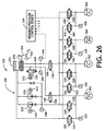
- the electric system includes a plurality of electric power sources to which there are connected a plurality of electrically operated loads or devices, which are collectively referred to as "a load device 50".
- the plurality of electric power sources consist of a main power source 40 and an auxiliary power source in the form of an auxiliary battery 42.
- the main power source 40 is principally constituted by a primary battery which is charged by a selected one of the electric motor 22 and the electric generator 24, which serve as battery charging devices.
- the electric motor 22, the electric generator 24 and the primary battery of the main power source 40 will be described in detail.
- the main power source 40 has a nominal voltage higher than that of the auxiliary battery 42, and the auxiliary battery 42 is adapted to be charged by the main power source 40.
- the load device 30 is electrically connected to the main power source 40 through a common conduit 44 and a primary power source conduit 46, and to the auxiliary battery 42 through the common conduit 44 and an auxiliary power source conduit 48.
- the load device 30 includes a plurality of loads 50 (electrically operated devices) and a selector switch device 52.
- the plurality of loads 50 are provided for enabling the automotive vehicle to function as intended.
- the loads 50 may include: an electrically operated power steering device; an electrically operated fuel pump; an electrically operated compressor for an air conditioner; head lights; electric motors for power windows; an electric motor or motors for a window wiper or wipers; an electrically operated braking system (including electric motors for pumps, electric motors for actuating brake pads with friction members, solenoid-operated control valves for controlling pressures and direction of flow of a working fluid, etc.); and audio devices.
- the individual loads 50 are given different priorities in the order of importance of their functions assigned in the automotive vehicle. For instance, the load 50a associated with the electrically operated braking system is given the highest priority, and the load 50b associated with the electrically operated power steering device is given the second highest priority.
- the selector switch device 52 is provided for selectively connecting each of the loads 50 except the load 50a having the highest priority, to the main power source 40 and the auxiliary battery 42.
- the selector switch device 52 has a plurality of switching elements associated with the plurality of loads 50.
- the load 50a having the highest priority is held connected to both the main power source 40 and the auxiliary battery 42.
- the selector switch device 52 has an input terminal 54 which receives a LOAD SELECTING signal for controlling the switching elements so as to select the loads 50 that are connected to the main power source 40 and the auxiliary battery 42.
- Each of the loads 50 has three terminals, which consist of: (a) an output terminal 56 for generating a LOAD STATE signal indicative of the operating state of the load 50 in question; (b) an input terminal 58 for receiving a LOAD OPERATING signal for operating the load 50 in question; and (c) an input terminal 59 for receiving a CURRENT LIMITING signal for limiting the maximum value of an electric current that can be applied to the load 50 in question.
- the electric system further includes a voltage regulating device 60, as shown in Fig. 1.
- the voltage regulating device 60 is connected to the main power source conduit 46, and incorporates a switching portion 62, a transformer 64, a rectifying circuit 66, a detector 70, a control portion 72, and an input/output (I/O) interface 74.
- the transformer 64 which is indicated in parenthesis in Fig. 1 is not an element essential to the voltage regulating device 60.
- Figs. 3 and 4 show one example of a combination of the switching portion 62, the transformer 64 and the rectifying circuit 66, while Fig. 5 shows another example of the combination where the drive power source provided on the automotive vehicle consists of only the engine 20.
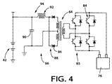
- the main power source 50 is principally constituted by a primary battery 76, which is connected to the electric motor 22 and the electric generator 24 through an inverter 78.
- a direct current discharged from the primary battery 76 is converted by the inverter 78 into an alternating current to be supplied to the electric motor 22 for driving the drive wheels 23.
- an alternating current generated by the electric motor 22 operated by a torque of the rotating drive wheels 23 is converted by the inverter 78 into a direct current which is used for charging the primary battery 76.
- the inverter 78 is further assigned to convert an alternating current generated by the electric generator 24 operated by the engine 20, into a direct current used for charging the primary battery 76.
- the electric generator 24 functions as a starter for starting the engine 20 when the electric generator 24 is energized with the electric energy supplied from the primary battery 76.
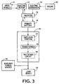
- the switching portion 62, the transformer 64 and the rectifying circuit 66 cooperate to constitute a DC/DC converter 82, which is schematically shown in Fig. 3.
- the DC/DC converter 82 includes a series connection of (a) a transistor bridge circuit 85 having a plurality of transistors 84 which serves as the switching portion 62, (b) the above-indicated transformer 64 having a primary coil and a secondary coil, and (c) the above-indicated rectifying circuit 66 for rectifying and smoothing the alternating current supplied from the secondary coil of the transformer 64, into a direct current.
- the rectifying circuit 66 includes a rectifier principally constituted by a diode 86, and a smoothing circuit 94 having a capacitor 90 and a coil 92.
- the rectifying circuit 66 has an output terminal to which the auxiliary battery 42 and the load device 30 are connected.
- the main power source 40 is principally constituted by an electric generator (in the form of an alternator, for example) which is driven by the engine 20.
- a combination of the switching portion 62 and the rectifying circuit 66 (and not including the transformer 64) serves as a so-called regulator 98.
- the regulator 98 is a series connection of the above-indicated switching portion 62 having a plurality of transistors, and the above-indicated rectifying circuit 66 having a capacitor and a coil.
- the rectifying circuit 66 has an output terminal to which the auxiliary battery 42 and the load device 30 are connected.
- the above-indicated detector 70 is arranged to detect an amount of an electric current applied from the voltage regulating device 60 to the load device 30, and applies a signal indicative of the detected amount of electric current to the I/O interface 74.
- the amount of electric current detected by the detector 70 does not necessarily represent an electric current ("load current") flowing through the load device 30, which represents a load acting on the load device 30, since the electric current may be supplied from the voltage regulating device 60 to both the load device 30 and the auxiliary battery 42, and since the load device 30 may be supplied with electric currents from both the voltage regulating device 70 and the auxiliary battery 42.
- the detector 70 detects a voltage of the load device 30 ("load voltage"), as being equal to the output voltage of the voltage regulating device 60 and the voltage of the auxiliary battery 42.
- load voltage a voltage of the load device 30
- the detector 70 detects the load voltage as being equal to the voltage of the auxiliary battery 42.
- An output signal of the detector 70 is also applied to the I/O interface 74.
- the above-indicated control portion 72 is connected to the I/O interface 74 and the switching portion 62, and is adapted to receive the output signal of the detector 70.
- the control portion 72 is principally constituted by a computer 100 incorporating a CPU, a ROM and a RAM.
- the computer 100 is operated with an electric power supplied from the auxiliary battery 42.
- the ROM indicated above stores various control routines such as a voltage regulating routine and a self-diagnostic routine.
- the voltage regulating routine is formulated to generate a drive command to be applied to the switching portion 62, for controlling the output voltage of the voltage regulating device 60 to a desired value by lowering the voltage of the main power source 40 by a feedback control on the basis of the output signal of the detector 70. Described more specifically, the voltage regulating routine is formulated to turn on and off the switching portion 62, upon reception of an external OUTPUT PERMIT command, so that the output voltage of the voltage regulating device 70 is made equal to 14V, and to hold the switching portion 62 in an open state for disconnecting the main power source 40 from the load device 30, upon reception of an external OUTPUT INHIBIT command, so that the output voltage of the voltage regulating device 60 is zeroed (made equal to 0V).
- the self-diagnostic routine is formulated to diagnose the main power source 40 and the voltage regulating device 60 for any abnormality, on the basis of a DETECT signal in the form of the output signal of the detector 70.
- Fig. 1 also shows flows of the electric current between the main power source 40 and the auxiliary battery 42 and load device 30, and between the load device 30 and the main power source 40 and auxiliary battery 42, when the voltage regulating device 60 is normally operating, and when the power source monitoring 10 is operating to diagnose the auxiliary battery 42 while the output voltage of the voltage regulating device 60 is limited.
- the flows of the electric current during the normal operation of the voltage regulating device 60 will be described just below, and the flow of the electric current during the diagnosis will be described later in relation to an operation of the power source monitoring device 10.
- the voltage regulating device 60 has the nominal voltage of 14V, while the auxiliary battery 42 has the nominal voltage of 12V. Further, the maximum current that can be supplied from the voltage regulating device 60 is 130A. Accordingly, when both a main power source device consisting of the main power source 40 and the voltage regulating device 60 and the auxiliary battery 42 are normal and when the electric current to be consumed by the load device 30 ("load current") is not larger than 130A, the electric current flows from the main power source device to the load device 30 for operating the load device 30, as indicated at "b" in Fig. 1, while at the same time the electric current flows from the main power source device to the auxiliary battery 42 so as to charge the auxiliary battery 42, as indicated at "a” in Fig. 1.
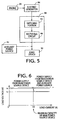
- the load voltage (which is equal to the voltage of the voltage regulating device 60) is 14V, as indicated in Fig. 6, and the electric current does not flow from the auxiliary battery 42 to the load current 30.
- the load voltage is lowered to 12V which is the nominal voltage of the auxiliary battery 42, but the amount of the electric current applied to the load device 30 is larger than the maximum amount of the main power source device, as indicated in Fig. 6.
- the power source monitoring device 10 is principally constituted by a computer 110 incorporating a CPU, a ROM and a RAM.
- the computer 110 is operated with an electric power supplied from the auxiliary battery 42.
- the ROM of the computer 110 stores various control routines such as a diagnostic routine and an abnormality handling routine.
- the diagnostic routine is formulated to diagnose or check the auxiliary battery 42 for detecting an abnormality that the capacity of the auxiliary battery 42 to supply electric power to the load device 30 has been abnormally lowered. This capacity may be lowered due to deterioration of the auxiliary battery 42 arising from an increase in the internal electric resistance above the upper limit, or due to an insufficient amount of charging of the auxiliary battery 42 by the main power source 40.
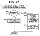
- the abnormality handling routine is executed when an abnormality of the auxiliary battery 42 is found by execution of the diagnostic routine.
- This abnormality handling routine is formulated to provide the operator of the automotive vehicle with a warning on a display device 112 connected to the power source monitoring device 10, in order to avoid any inconvenience which may result from the abnormality.
- the abnormality handling routine is further formulated to limit or select the loads 50 of the load device 30 that are permitted to be operated, and to limit the maximum electric current to be supplied to the selected loads 50, in order to prevent the amount of electric current consumed by the load device 30 from exceeding the maximum value, after the abnormality is found by the diagnostic routine.
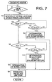
- Fig. 7 there is illustrated the diagnostic routine. While the diagnostic routine will be described by reference to the flow chart, a concept underlying the diagnostic routine will be first explained.
- the graph of Fig. 8 shows different relationships between the load current (A) and the load voltage (V), namely, different A-V curves, which correspond to respective three cases when the load current is larger than the maximum value of the main power source device (40, 60): 1) a case where the auxiliary battery 42 is in the normal state; 2) a case where the auxiliary battery 42 is insufficiently charged; and 3) a case where the auxiliary battery 42 is deteriorated.
- the load voltage is held at 12V for a relatively long time after the load current has exceeded the maximum value of 130A. After this relatively long time has passed, the load voltage drops such that the rate of drop of the load voltage is initially low and is subsequently high.
- the load voltage begins to drop immediately after the load current has exceeded the maximum value of 130A. In this case, the load voltage drops such that the rate of drop of the load voltage is initially low and is subsequently high. Where the auxiliary battery 42 is deteriorated, the load voltage begins to drop immediately after the load current has exceeded the maximum value of 130A, such that the rate of drop is high from the beginning of the drop.
- the load voltage of the load device 30 must be detected by the detector 70 while an electric current is flowing from the auxiliary battery 42 to the load device 30.
- the electric current flows from the auxiliary battery 42 to the load device 30 when the total amount of the electric currents flowing from the main power source 40 and the auxiliary battery 42 is larger than 130A, or when the output voltage of the voltage regulating device 60 is limited to a value lower than the voltage of the auxiliary battery 42 so that the electric current flows to the load device 30 from only the auxiliary battery 42.
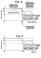
- the graph of Fig. 9 shows a drop of the load voltage of the load device 30 with time t after the output voltage of the voltage regulating device 60 is lowered below the voltage (12V) of the auxiliary battery 42 at a point of time t 0 .
- the load voltage drops since the voltage of the auxiliary battery 42 is lowered due to consumption of the electric energy or power stored in the auxiliary battery 42 where the electric current is supplied from only the auxiliary battery 42 to the load device 30, and since the voltage of the auxiliary battery 42 and the load voltage drop together while these voltages are kept equal to each other.
- the V-t curves of Fig. 9 representing the relationship between the load voltage (V) and the time (t) are similar to the V-A curves of Fig. 8 representing the relationship between the load voltage (V) and the load current (A). Described in detail, where the auxiliary battery 42 is in the normal state, the load voltage is kept at 12V after the output voltage limitation of the voltage regulating device 50 is initiated, until the load current increases to a relatively large value. Then, the load voltage drops such that the rate of drop of the load voltage is initially low and is subsequently high. Where the auxiliary battery 42 is in an insufficiently charged state, the load voltage begins to drop immediately after the output voltage limitation of the voltage regulating device 50 is initiated.
- the load voltage drops such that the rate of drop of the load voltage is initially low and is subsequently high.
- the load voltage begins to drop immediately after the initiation of the output voltage limitation of the voltage regulating device 60, such that the rate of drop is high from the beginning of the drop.
- the diagnostic routine is formulated to check whether the auxiliary battery 42 is in a deteriorated state or in an insufficiently charged state, depending upon a characteristic of a chronological change in the load voltage detected by the detector 70 while the output voltage of the voltage regulating device 60 is limited.
- the diagnostic routine is repeatedly executed at a time interval T s which is determined by the characteristic of the chronological change in the detected load voltage.
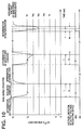
- the graph of Fig. 10 shows methods of detecting or determining the normal state, insufficiently charged state and deteriorated state of the auxiliary battery 42, according to the diagnostic routine.
- the auxiliary battery 42 is determined to be placed in the normal state, if the load voltage V LD is kept at a level not lower than the nominal voltage V b (12V) of the auxiliary battery 42 for a predetermined first threshold time t c after the initiation of the output voltage limitation of the voltage regulating device 60. In this case, the output voltage limitation is terminated when the predetermined threshold time t c has passed after the initiation of the output voltage limitation.
- the auxiliary battery 42 is determined to be placed in the deteriorated state, if the load voltage V LD has lowered to a predetermined first threshold level V thf below the nominal voltage V b before a predetermined second threshold time t thf shorter than the first threshold time t c has passed after the initiation of the output voltage limitation. In this case, the output voltage limitation is terminated when the load voltage V LD has been lowered to the first threshold level V thf .
- the auxiliary battery 42 is determined to be placed in the insufficiently charged state, if the load voltage V LD has been lowered to a second threshold level V the between the nominal voltage V b and the first threshold level V thf before the first threshold time t c . In this case, the output voltage limitation is terminated when the load voltage V LD has been lowered to the second threshold value V the .
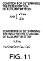
- a condition which should be satisfied for determining that the auxiliary battery 42 is in the deteriorated state is expressed as follows, as indicated in Fig. 11: V LD ⁇ V thf AND t ⁇ t thf wherein "t" represents a time from a moment of initiation of the output voltage limitation of the voltage regulating device 60 to a moment at which the load voltage V LD has been lowered to the first threshold level V thf .
- a condition which should be satisfied for determining that the auxiliary battery 42 is in the insufficiently charged state is expressed as follows, as also indicated in Fig. 11: V LD ⁇ V the
- the limitation of the output voltage of the voltage regulating device 60 must be effected such that the output voltage is lower than the actual voltage of the auxiliary battery 42.
- the computer 100 of the control portion 72 of the voltage regulating device 60 and the computer 110 of the power source monitoring device 10 are connected to the auxiliary battery 42.
- the computers 100, 110 are designed to be normally operable when the voltage applied to those computers is at least 9V. If the output voltage of the voltage regulating device 60 is lowered to a level lower than 9V for the purpose of diagnosing the auxiliary battery 42, there is no assurance that the computers 100, 110 are normally operable.
- a lower limit V dd of the output voltage of the voltage regulating device 60 when the output voltage is limited for the diagnostic purpose is determined to be lower than the above-indicated first threshold level V thf and higher than a permissible lowest voltage level V L of the computers 100, 110. Accordingly, the permissible lowest voltage level V L , the lower limit V dd , the first threshold level V thf , the second threshold level V the and the nominal voltage level V b of the auxiliary battery 42 have following relationship, as indicated in parenthesis at the bottom of Fig. 11: V L ⁇ V dd ⁇ V thf ⁇ V the ⁇ V b
- amounts of the electric current consumed by the load device 30 during respective successive periods of limitation of the output voltage of the voltage regulating device 60 are not necessarily equal to each other. Since the successive periods of limitation of the output voltage usually occur during running of the vehicle, it is not always proper to control the amounts of the electric current consumed by the load device 30 during the respective periods of limitation of the output voltage such that those amounts are made equal to a certain value.
- the threshold times t c , t thf may be fixed values according to the present invention.
- the present embodiment is arranged such that the threshold times t c , t thf are changed depending upon the load current such that the times t c , t thf are shorter when the load current is relatively large than when it is relatively small, in view of a fact that the amount of consumption of the electric energy stored in the auxiliary battery 42 increases with an increase in the load current, so that the rate of reduction of the voltage of the auxiliary battery 42 and therefore the load voltage increases with the load current.
- the detector 70 which is provided to detect the electric current supplied from the voltage regulating device 60 to the load device 30, is not capable of directly detecting the electric current supplied from the auxiliary battery 42 to the load device 30.
- the load current of the load device 30 can be detected by the detector 30 immediately before the initiation of the output voltage limitation of the voltage regulating device 50, since the electric power is supplied to the load device 30 from only the voltage regulating device 60 before the incitation of the output voltage limitation. Further, it is possible to assume that the load current is kept substantially constant while the output voltage of the device 60 is limited, namely, while the output voltage is held lower than the actual voltage of the auxiliary battery 42.
- the load current is equal to the electric current supplied from the auxiliary battery 42 to the load device 30 while the output voltage of the device 60 is limited.
- the load current detected by the detector 70 immediately before the initiation of the output voltage limitation of the device 60 is used as the electric current of the auxiliary battery 42 during the output voltage limitation.
- the threshold times t c , t thf be changed not on the basis of one detected value of the load current, but on the basis of a value obtained by smoothing a plurality of detected values of the load current. For instance, it is preferable to use an average of a plurality of detected values of the load current.
- the threshold voltage levels V the , V thf may be fixed values according to this invention. In the present embodiment, however, the threshold values V the , V thf are changed depending upon the load current such that these values V the , V thf are larger when the load current is relatively large than when it is relatively small, in view of a fact that the rate of reduction of the load voltage increases with an increase in the load current, due to deterioration of the auxiliary battery 42 and/or an operating response characteristic of the voltage regulating device 60.
- the manner of detecting the load current to determine the threshold levels V the , V thf is the same as described above with respect to the threshold times t c , t thf .
- the time interval T s may be a fixed value according to the present invention.
- the amount of electric energy stored in the auxiliary battery 42 which is consumed by the load device 30 for the purpose of monitoring or diagnosing the auxiliary battery 42, increases with an increase in the load current of the load device 30. That is, the load acting on the auxiliary battery 42 during its diagnosis increases with the load current. Accordingly, the amount of reduction of the voltage of the auxiliary battery 42 increases with the load current.
- the tine interval T s is changed such that the time interval T s is longer when the load current is relatively large than when it is relatively small.
- the manner of detecting the load current to determine the time interval T s is the same as described above with respect to the threshold times t c , t thf and threshold levels V the , V thf .
- the amount of electric energy stored in the primary battery 76 of the main power source 40 is smaller than a predetermined lower limit, it is preferable to inhibit the diagnosis of the auxiliary battery 42 by increasing the time interval T s substantially to infinity. If the output voltage of the voltage regulating device 60 is limited to diagnose the auxiliary battery 42 when the amount of electric energy stored in the primary battery 76 is smaller than the lower limit, the voltage of the primary battery 76 may not be raised back to the original level in a short time after the limitation of the output voltage of the device 60 is cancelled. For this reason, it is preferable to inhibit the diagnosis of the auxiliary battery 42 when the electric energy amount stored in the primary battery 76 is smaller than the lower limit.
- the amount of electric power consumed by the load or loads 50 connected to only the primary battery 76 is larger than a predetermined upper limit, it is preferable to inhibit the diagnosis of the auxiliary battery 42 by increasing the time interval T s substantially to infinity. If the output voltage of the voltage regulating device 60 is limited to diagnose the auxiliary battery 42 when the electric power consumed by the loads 50 connected to only the primary battery 76 is larger than the upper limit, the voltage of the primary battery 76 may not be raised back to the original level in a short time after the limitation of the output voltage of the device 60 is cancelled. For this reason, it is preferable to inhibit the diagnosis of the auxiliary battery 42 in the above case.
- the ignition switch of the vehicle is turned off by the vehicle operator.
- the diagnostic routine is repeatedly executed. Each cycle of execution of the diagnostic routine is initiated with step S1 to determine whether the cycle time T s has passed after the termination of the last cycle. If an affirmative decision (YES) is obtained in step S1, the control flow goes to step S2 to generate a signal for initiating the limitation of the output voltage of the voltage regulating device 60. As a result, the discharging of the auxiliary battery 42 is initiated, so that an electric current flows from the auxiliary battery 42 to the load device 30, as indicated at "c" in Fig. 1.
- Step S2 is followed by step S3 to determine whether the time t which has passed after the initiation of the output voltage of the device 60 is equal to or shorter than the second threshold time t thf , if an affirmative decision (YES) is obtained in step S3, the control flow goes to step S7 to determine whether the load voltage V LD calculated on the basis of the output signal of the detector 70 is equal to or lower than the first threshold level V thf . If a negative decision (NO) is obtained in step S7, the control flow goes back to step S3.
- step S7 If the load voltage V LD has been lowered to the first threshold level V LD as a result of repeated implementation of steps S3 and S7, an affirmative decision (YES) is obtained in step S7, and the control flow goes to step S8 to determine that the auxiliary battery 42 is in a deteriorated state. Then, the control flow goes to step S6 to generate an OUTPUT LIMIT command for terminating the limitation (reduction) of the output voltage of the voltage regulating device 60. Thus, one cycle of execution of the diagnostic routine is terminated.
- step S4 determines whether the time t is equal to or shorter than the first threshold time t c . If an affirmative decision (YES) is obtained in step S4, the control flow goes to step S9 to determine whether the load voltage V LD calculated on the basis of the output signal of the detector 70 is equal to or lower than the second threshold level V the . If a negative decision (NO) is obtained in step S9, the control flow goes back to step S4.
- step S9 If the load voltage V LD has been lowered to the second threshold level V the as a result of repeated implementation of steps S4 and S9, an affirmative decision (YES) is obtained in step S9, and the control flow goes to step S10 to determine that the auxiliary battery 42 is in an insufficiently charged state, and then to step S6 to terminate the limitation of the output voltage of the voltage regulating device 60. Thus, one cycle of execution of the diagnostic routine is terminated.
- step S4 If the time t becomes longer than the first threshold time t c before the load voltage V LD has been lowered to the second threshold level V the , a negative decision (NO) is obtained in step S4, and the control flow goes to step S5 to determine that the auxiliary battery 42 is in the normal state. Thus, one cycle of execution of the diagnostic routine is terminated.
- step S21 determines whether the diagnostic routine has revealed that the auxiliary battery 42 is in the deteriorated state, according to the diagnostic routine. If an affirmative decision (YES) is obtained in step S21, the control flow goes to step S22 to activate the display device 112 for warning the vehicle operator that the auxiliary battery 42 is in the deteriorated state.
- Step S23 is provided to select those ones of the plurality of loads 50 which are permitted to be operated with the electric power supplied from the main power source 40. This selection is made according to the priorities given to the individual loads 50. According to the selected loads 50, the LOAD SELECTING signal indicated above is applied to the selector switch device 52. Step S23 is followed by step S24 wherein the CURRENT LIMITING signal indicated above is generated for limiting the maximum permissible amount of electric current to be applied to the selected loads 50.
- Steps S23 and S24 cooperate to prevent a total amount of consumption of the electric current by the loads 50 from exceeding the maximum permissible amount of electric current of the main power source 40. Then, the execution of the present abnormality handling routine is inhibited until the ignition switch provided on the vehicle is turned on again.
- step S21 If the diagnostic routine has revealed that the auxiliary battery 42 is not in the deteriorated state, a negative decision (NO) is obtained in step S21, and the control flow goes to step S25 to determine whether the diagnostic routine has revealed that the auxiliary battery 42 is in the insufficiently charged state. If an affirmative decision (YES) is obtained step S25, the control flow goes to step S26 to activate the display device 112 for warning the vehicle operator that the auxiliary battery 42 is in the insufficiently charged state. Then, step S27 similar to step S23 is implemented to limit the loads 50 that are permitted to be operated with the electric power supplied from the main power source 40. Step S27 is followed by step S28 to limit the maximum permissible amount of electric current of the selected loads 50, as in step S24.
- steps S27 and S28 implemented when the auxiliary battery 42 is in the insufficiently charged state however, the number of the selected loads 50 that are permitted to be operated and/or the maximum permissible electric current of the selected loads 50 is/are larger than in steps S23 and S24 implemented when the auxiliary battery 42 is in the deteriorated state, since the power supply capacity of the auxiliary battery 42 is larger when it is insufficiently charged than when it is deteriorated. Then, the execution of the abnormality handling routine is inhibited until the ignition switch provided on the vehicle is turned on again.
- the diagnostic routine has not revealed that the auxiliary battery 42 is in the deteriorated or insufficiently charged state, the negative decision (NO) is obtained in both of the steps S21 and S25, and one cycle of execution of the abnormality handling routine is terminated. Then, the next cycle of execution of the routine is initiated without the ignition switch being once turned off and turned on again.
- an exclusive disconnecting switch may be provided between the main power source 40 and the auxiliary battery 42, in addition to the switching portion 62, for disconnecting the auxiliary battery 42 from the main power source 40, so that the load device 30 is operated to diagnose the auxiliary battery 42 while the switch is open.
- this form of the present invention has some disadvantages. Namely, the exclusive disconnecting switch is required, and the load device 30 may not be normally operated for performing some required or intended function or functions when the voltage of the auxiliary battery 42 is relatively low while the disconnecting switch is open.
- the auxiliary battery 42 is one example of a subject power source to be diagnosed by the power source monitoring device 10, while the main power source 40 is one example of a non-subject power source as distinguished from the subject power source, which non-subject power source has a nominal voltage higher than that of the subject power source.
- a portion of the computer 110 assigned to execute the diagnostic routine of Fig. 7 constitutes an example of a first diagnosing device for determining whether the subject power source is abnormal or not while the electric power is supplied from only the non-subject power source to the load device, and that the limitation of the output voltage of the voltage regulating device 60 is one form of a power supply state in which the electric power is supplied to the load device 30.
- the diagnostic routine is executed at the time interval T s to diagnose the auxiliary battery 42 while the output voltage of the voltage regulating device 60 is held at a reduced level.
- the present second embodiment is adapted to diagnose the auxiliary battery 42 also when a large amount of electric current is supplied from both the main power source 40 and the auxiliary battery 42 to the load device 30.
- the output voltage of the voltage regulating device 60 is not limited or reduced, and the diagnosis of the auxiliary battery 42 is repeated at a time interval shorter than the time interval T s .
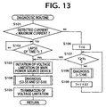
- the diagnostic routine in the present second embodiment is illustrated in the flow chart of Fig. 13. Like the diagnostic routine in the first embodiment, the present diagnostic routine is repeatedly executed. Each cycle of execution of the diagnostic routine is initiated with step S101 to determine whether the electric current detected by the detector 70, that is, the electric current supplied from the voltage regulating device 60 to the load device 30 is smaller than the maximum electric current of the voltage regulating device 60. This step S101 is provided to determine whether the above-indicated large amount of electric current is not supplied to the load device 30.
- step S101 If the detected electric current is smaller than the maximum electric current of the device 60, that is, if an affirmative decision (YES) is obtained in step S101, the control flow goes to step S102 to determine whether the predetermined time interval T s has passed after the termination of the last cycle of execution of the diagnostic routine. If an affirmative decision (YES) is obtained in step S102, the control flow goes to step S103 to initiate the limitation of the output voltage of the voltage regulating device 60, as in the first embodiment. Then, step S104 is implemented to effect the diagnosis of the auxiliary battery 42 on the basis of the voltage detected by the detector 70, that is, the load voltage. This diagnosis is effected in the same manner as in steps S3-S5 and S7-S10 in the first embodiment. Then, step S105 is implemented to terminate the limitation of the output voltage of the device 60. Thus, one cycle of execution of the diagnostic routine is terminated.
- step S101 If the detected electric current is not smaller than the maximum electric current of the voltage regulating device 60, a negative decision (NO) is obtained in step S101, and the control flow goes to step S106 to reset a time T, and then to step S107 to determine whether the time T is equal to or longer than the time interval T s . If a negative decision (NO) is obtained in step S107, the control flow goes to step S108 to effect the diagnosis of the auxiliary battery 42 based on the load voltage, as in step S104. Then, step S108 is implemented to increment the time T by ⁇ T. The increment ⁇ T is a time necessary to implement a series of steps S107-S109 once, and is shorter than the tine interval T s . Then, the control flow goes to step S107.
- step S107 If the time T has increased to the time interval T s as a result of repeated implementation of steps S107-S109, an affirmative decision (YES) is obtained in step S107, and the control flow goes to step S103 and the subsequent steps.
- step S101 may be modified to determine whether the large electric current is supplied to the load device 30, by determining whether the detected electric current is equal to the maximum electric current of the device 60 while the load voltage detected by the detector 70 is substantially equal to the nominal voltage of 12V of the auxiliary battery 42.
- a portion of the computer 110 assigned to implement steps S102-S105 of the diagnostic routine of Fig. 13 constitutes a first diagnosing device for determining whether the subject power source is abnormal or not, and that the limitation of the output voltage of the voltage regulating device 60 is one form of a power supply state in which the electric power is supplied to the load device.
- the main power source 40 is an example of the non-subject power source
- a portion of the computer 110 assigned to implement steps S101 and S106-S109 of the diagnostic routine of Fig. 13 constitutes a second diagnosing device for determining whether the subject power source is abnormal or not while the electric power is supplied from both the non-subject power source and the subject power source.
- the diagnostic routine is executed to diagnose the auxiliary battery 42 periodically at the predetermined time interval T s while the output voltage of the voltage regulating device 60 is limited or held at the predetermined lowered level.
- the present third embodiment is adapted to diagnose the subject power source in the form of the auxiliary battery 42 when a VEHICLE ENABLE signal for enabling the vehicle to perform the intended function is generated by a manual operation by the vehicle operator.
- the diagnosis in this embodiment is effected without output voltage limitation of the voltage regulating device 60.
- the present embodiment is based on a design of the vehicle wherein upon generation of the VEHICLE ENABLE signal by a manual operation by the vehicle operator (for example, by turning on the ignition switch of the vehicle), the load device 30 is temporarily disconnected from the main power source 40 by the switching portion 62 of the voltage regulating device 60, so that the load device 30 is supplied with the electric power from only the auxiliary battery 42.
- the vehicle is designed as described above for the following reason, for example. Namely, when the VEHICLE ENABLE signal is generated, it is desirable that the capacitor in the inverter 78 be charged in a short time. To this end, the load device 30 is temporarily disconnected from the primary battery 76 of the main power source 76 when the VEHICLE ENABLE signal is generated. Therefore, the present third embodiment does not require controlling the voltage regulating device 60 for the sole purpose of diagnosing the auxiliary battery 42.
- the load device 30 To diagnose the auxiliary battery 42, the load device 30 must be operated with the electric power being supplied thereto from the auxiliary battery 42.
- the VEHICLE ENABLE signal When the VEHICLE ENABLE signal is generated, the load device 30 is not activated at all by the vehicle operator in most cases.
- the threshold voltage levels V the , V thf and threshold time t c are preferably changed depending upon the actual load current of the load device 30.
- the VEHICLE ENABLE signal is generated, however, the load current cannot be obtained on the basis of the electric current detected by the detector 70 as in the first embodiment, since the load device 30 is disconnected from the main power source 40.
- the load device 30 is activated upon generation of the VEHICLE ENABLE signal, to perform a suitable operation for checking the operating state of the load device 30 such as an operation for checking the initial state of the load device 30, such that the operation of the load device 30 will not cause the vehicle operator to feel uneasy with that operation.
- a suitable operation for checking the operating state of the load device 30 such as an operation for checking the initial state of the load device 30, such that the operation of the load device 30 will not cause the vehicle operator to feel uneasy with that operation.
- the amount of electric power consumed by the load device 30 is known, so that the auxiliary battery 42 can be diagnosed with consistently high accuracy, without changing the threshold levels V the , V thf and time T c .
- the vehicle operator may try to start the engine 20 by turning on the ignition switch with the auxiliary battery 42 being connected to another or assisting power source (for example, a 12V battery of another vehicle which is called for the purpose of starting the engine 20). In this case, no electric current is applied from the auxiliary battery 42 to the load device 30, and the auxiliary battery 42 cannot be diagnosed as intended.
- another or assisting power source for example, a 12V battery of another vehicle which is called for the purpose of starting the engine 20.
- the present embodiment is adapted to check if the auxiliary battery 42 is connected to the assisting power source, upon generation of the VEHICLE ENABLE signal, and provide a warning message prompting the vehicle operator to disconnect the auxiliary battery 42 from the external assisting power source, if the checking reveals that the auxiliary battery 42 is connected to the external assisting power source.
- the vehicle is placed in a VEHICLE DISABLE state for inhibiting the operations of the vehicle normally performed upon generation of the VEHICLE ENABLE signal such as an operation to start the engine.
- step S201 determines whether the VEHICLE ENABLE signal has been generated by a manual operation by the vehicle operator. Where the vehicle is of a manual transmission type (hereinafter referred to as "MT type"), it is determined that the VEHICLE ENABLE signal has been generated, if the ignition switch has been turned on.
- MT type manual transmission type
- the vehicle is of an automatic transmission type (hereinafter referred to as "AT type")
- AT type automatic transmission type
- VEHICLE ENABLE signal has been generated, if the following two conditions (a) and (b) have been simultaneously satisfied, for example: (a) the condition that the ignition switch has been turned on; and (b) a shifting member for shifting the automatic transmission is placed in one of a drive position D and a neutral position N.
- Step S201 is repeatedly implemented as long as a negative decision (NO) is obtained.
- a negative decision NO
- YES affirmative decision
- Step S202 is implemented to determine whether there is a possibility that the auxiliary battery 42 is aided by another or external assisting power source.
- An affirmative decision (YES) is obtained in step S202 if a predetermined one of the following three conditions is satisfied, if predetermined at least two of these three conditions are simultaneously satisfied, if any one of these three conditions is satisfied, or if at least two of these three conditions are simultaneously satisfied:
- step S202 If there is a possibility that the auxiliary battery 42 is aided by the external power source, the affirmative decision (YES) is obtained in step S202, and the control flow goes to step S208 to activate the display device 112 for providing the vehicle operator with a warning message "Do not connect the auxiliary battery to an external assisting power source.” Then, step S209 is implemented to place the vehicle in the VEHICLE DISABLE state described above. Described in detail, the main power source 40 is inhibited from energizing the electric generator 24 (which is selectively operated as the engine starter). Subsequently, the execution of the present diagnostic routine is inhibited until the ignition switch is turned off.
- step S202 If a negative decision (NO) is obtained in step S202, the control flow goes to step S203 wherein the OUTPUT INHIBIT command described above is applied to the voltage regulating device 60.
- the OUTPUT INHIBIT command causes the main power source 40 to be disconnected from the load device 30 and the auxiliary battery 42, for supplying the electric power from the main power source 40 preferentially to the inverter 78, so that charging of the capacitor of the inverter 78 can be completed in a short time.
- step S204 the control flow goes to step S204 to initiate a predetermined operation (hereinafter referred to as "battery diagnosing operation") of the load device 30 for the purpose of diagnosing the auxiliary battery 42.
- step S205 is implemented to diagnose the auxiliary battery for any abnormality, on the basis of the load voltage detected by the detector 70. This diagnosis is effected in the same manner as in steps S3-S5 and S7-S10 of the first embodiment.
- step S206 is implemented to terminate the battery diagnosing operation of the load device 30.
- Step S206 is followed by step S207 to cancel the OUTPUT INHIBIT command, and generate the OUTPUT PERMIT command for commanding the voltage regulating device 60 to permit the main power source 40 to be connected to the load device 30 and the auxiliary battery 42. Then, the execution of the present diagnostic routine is inhibited until the ignition switch is turned off.
- the present third embodiment is arranged to effect the diagnosis of the auxiliary battery 42 only when the VEHICLE ENABLE signal is generated.
- This arrangement of limiting the opportunity of effecting the diagnosis is considered not to cause a problem because the state of the auxiliary battery 42 is considered not to change to a considerable extent during running of the vehicle. Rather, the present arrangement of limiting the opportunity of effecting the diagnosis to the moment of generation of the VEHICLE ENABLE signal contributes to an increase in the stability of the amount of electric power consumed by the load device 30 during the diagnosis, and an increase in the accuracy of the diagnosis.
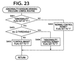
- step S151 determines whether the diagnostic routine has revealed that the auxiliary battery 42 is in the deteriorated state. If an affirmative decision (YES) is obtained in step S251, the control flow goes to step S252 to activate the display device 112 for warning the vehicle operator that the auxiliary battery 42 is in the deteriorated state. Then, step S253 is implemented to place the vehicle in the VEHICLE DISABLE state. Then, the execution of the present routine is inhibited until the ignition switch is turned on again.
- step S201 If the diagnostic routine has not revealed that the auxiliary battery 42 is not in the deteriorated state, a negative decision (NO) is obtained in step S201, and the control flow goes to step S254 to determine whether the diagnostic routine has revealed that the auxiliary battery 42 is in the insufficiently discharged state. If an affirmative decision (YES) is obtained in step S254, the control flow goes to step S255 to activate the display device 112 for warning the vehicle operator that the auxiliary battery 42 is in the insufficiently charged state.
- the control flow goes to step S256 to place the vehicle in an energy saving mode.
- the loads 50 that are permitted to be operated with the electric power from the main power source 40 are limited, namely, selected according to the priorities given to the loads 50.
- the LOAD SELECTING signal described above is is generated and applied to the selector switch device 52.
- the CURRENT LIMITING signal described above is generated to limit the electric current to be applied to the selected loads 50, so as to prevent the amount of consumption of the electric current by the load device 30 from exceeding the maximum electric current of the main power source 40. Subsequently, the execution of the abnormality handling routine is inhibited until the ignition switch is turned on again.
- a portion of the computer 110 assigned to execute the diagnostic routine of Fig. 14 constitutes an example of a first diagnosing device for determining whether the subject power source is abnormal or not while the electric power is supplied from only the non-subject power source to the load device, and that the limitation of the output voltage of the voltage regulating device 60 is one form of a power supply state in which the electric power is supplied to the load device 30.
- the main power source 40 is one example of a non-subject power source as distinguished from the subject power source
- a portion of the computer 110 assigned to execute the diagnostic routine of Fig. 14 constitutes an example of means for effecting the diagnosis of the subject power source while the vehicle is in a substantially stopped state.
- the switching portion 62 constitutes an example of a device for controlling connection and disconnection of the load device 30 and the subject power source 42 with respect to the non-subject power source 40, while a portion of the computer 110 assigned to implement steps S204 and S207 constitutes an example of means for performing a predetermined operation of the load device 30 with the electric power supplied from the subject power source 42.
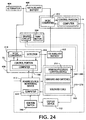
- a vehicle provided with a power source monitoring device 140 in the present fourth embodiment has only the engine 20 as the drive power source.
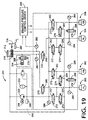
- a plurality of power sources include an electric generator 96 operated by the engine 20 to generate an electric power, and a battery 130, as shown in Fig. 16, as in the electric system shown in Fig. 5.
- the electric generator 96 and the battery 130 are connected to the load device 30.
- the electric generator 96 is connected to the voltage regulating device 60 in the form of a regulator 98 including the switching portion 62, the rectifying circuit 66, the detector 70 and the control portion 72.
- the engine 20 is started by a starter 132 which is operated with an electric power supplied from the battery 130.
- the switching portion 62 and the detector 70 of the regulator 98 there is connected the above-indicated power source monitoring device 140 constructed according to the present embodiment.
- the power source monitoring device 140 is principally constituted by a computer 142 incorporating a CPU, a ROM and a RAM.
- the computer 142 is operated with an electric power supplied from the battery 130.
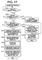
- the ROM stores various control routines such as a diagnostic routine, and an abnormality handling routine identical with that of the third embodiment of Fig. 15. While the diagnostic routine will be described in detail by reference to the flow chart of Fig. 17, no detailed description will be provided with respect to steps similar to those of the diagnostic routine in the third embodiment.
- the threshold levels V the , V thf and threshold time t c are fixed values, in view of an arrangement wherein the starter 132 is operated with the electric power supplied from the battery 130, to start the engine 20, when the VEHICLE ENABLE signal is generated.
- the battery 130 is diagnosed for an abnormality, on the basis of the output signal of the detector 70 when the amount of electric power consumed by the battery 130 is larger than a threshold value. This arrangement permits even a small degree of abnormality of the battery 130 which would not be detected if the electric power of the battery 130 were not consumed by the starter 132.
- the vehicle operator may start the engine 20 by manual cranking utilizing torques of the drive wheels 23 which are rotated by manual efforts to move the vehicle.
- the battery 130 cannot be diagnosed as intended, since the electric power stored in the battery 130 is not consumed by the starter 132.
- the present embodiment is adapted to check if the engine 20 is started by the manual cranking or not, upon generation of the VEHICLE ENABLE signal, and provide a warning message prompting the vehicle operator not to effect the manual cranking to start the engine 20, if the checking reveals the manual cranking of the engine 20.
- the vehicle is placed in the VEHICLE DISABLE state for inhibiting the operations of the vehicle normally performed upon generation of the VEHICLE ENABLE signal such as an operation to start the engine.
- step S301 determines whether the VEHICLE ENABLE signal has been generated by a manual operation by the vehicle operator.
- Step S301 is repeatedly implemented as long as a negative decision (NO) is obtained.
- YES affirmative decision
- Step S302 is implemented to determine whether there is a possibility that the engine 20 is started by manual cranking. Where the vehicle is of the MT type, an affirmative decision (YES) is obtained in step S302 if a predetermined one of the following five conditions is satisfied, if predetermined at least two of these five conditions, are simultaneously satisfied, if any one of these five conditions is satisfied, or if at least two of these five conditions are simultaneously satisfied:
- the affirmative decision is obtained in step S302 if a predetermined one of four conditions consisting of the above-indicated first, third and fourth conditions and a sixth condition described below is satisfied, if predetermined at least two of these four conditions are simultaneously satisfied, if any one of these four conditions is satisfied, or if at least two of these four conditions are simultaneously satisfied.
- the sixth condition is that the shifting member is operated from its parking position to another position. This sixth condition may be satisfied, if a shift lock mechanism for preventing starting of the AT type vehicle due to an erroneous operation of the shifting member is placed in the released position.
- step S302 If there is a possibility that the engine 20 is started by the manual cranking, the affirmative decision (YES) is obtained in step S302, and the control flow goes to step S303 to activate the display device 112 for providing the vehicle operator with a warning message "Do not start the engine by manual cranking". Then, step S304 is implemented to place the vehicle in the VEHICLE DISABLE state described above. Described in detail, the main power source 40 is inhibited from energizing the electric generator 24 (which is selectively operated as the engine starter). Subsequently, the execution of the present diagnostic routine is inhibited until the ignition switch is turned off.
- step S302 If there is not a possibility that the engine 20 is started by the manual cranking, a negative decision (NO) Is obtained in step S302, and the control flow goes to step S305 to determine whether there is a possibility that the battery 130 is aided by another or external assisting power source.
- step S305 If there is a possibility that the battery 130 is aided by the assisting power source, an affirmative decision (YES) is obtained in step S305, and the control flow goes to step S306 to activate the display device 112 for providing the vehicle operator with a warning message "Do not connect the battery to an external assisting power source.” Then, step S306 is implemented to place the vehicle in the VEHICLE DISABLE state described above. Subsequently, the execution of the present diagnostic routine is inhibited until the ignition switch is turned off.
- step S307 the negative decision (NO) is obtained in both of the steps S302 and S305, and the control flow goes to step S307 wherein the OUTPUT INHIBIT command described above is applied to the voltage regulating device 60 (regulator 98).
- control flow goes to steps S308-S311 identical with steps S203-S207 in the third embodiment.
- steps S308-S311 identical with steps S203-S207 in the third embodiment.
- one cycle of execution of the diagnostic routine is terminated.
- the execution of the present diagnostic routine is inhibited until the ignition switch is turned off.
- the battery 130 is one example of a subject power source to be diagnosed by the power source monitoring device 140, while the electric generator 96 is one example of a non-subject power source as distinguished from the subject power source.
- a portion of the computer 142 assigned to execute the diagnostic routine of Fig. 17 constitutes an example of a first diagnosing device for determining whether the subject power source is abnormal or not while the electric power is supplied from only the non-subject power source to the load device, and that the limitation of the output voltage of the voltage regulating device 60 is one form of a power supply state in which the electric power is supplied the load device 30.
- step S302 constitutes an example of means for effecting the diagnosis of the subject power source 130 when the amount of electric power of the subject power source which is consumed by the load device is larger than a threshold value.
- the monitoring device may be adapted to diagnose the subject power source for abnormality, by comparing an amount of change of the detected load voltage with predetermined threshold values.
- the amount of change of the detected load voltage is an amount of change of the load voltage value detected in each cycle of execution of the diagnostic routine, from the load voltage value detected in the first cycle of execution, or an amount of change of the load voltage value detected in each cycle of execution from the load voltage value detected in the preceding cycle, which amount of change represents the rate of change of the detected load voltage.
- While the computer for controlling the DC/DC converter is provided in addition to the computer of the power source monitoring device in the embodiments described above, a single computer may be used for controlling the DC/DC converter and for monitoring the subject power source.
- an alternator 202 serving as an electric generator and an auxiliary battery 204 are connected to a load device 200 through a DC/DC converter 206.
- the alternator 202 is operated by the engine 20 of the vehicle, to generate an electric power, while the auxiliary battery 204 is charged with the electric power generated by the alternator 202.
- the DC/DC converter 206 which is similar to that shown in Fig. 4, includes the switching portion 62 having the transistor bridge circuit 85, the transformer 64 and the rectifying circuit 66.
- the on/off control of the switching portion 62 is effected by the control portion 62 incorporating the computer 100, for regulating the electric power supplied to the load device 200.
- the DC/DC converter 206 (switching portion 62) is controlled so that the amount of electric power consumed by the load device 200 is made equal to a predetermined value, that is, so that the amount of electric power to be supplied to the load device 200 is made equal to a predetermined amount.
- the DC/DC converter 206 and the control portion 72 cooperate to constitute a major portion of a supply power regulating device 208.
- the load device 200 in the present embodiment includes a plurality of electrically operated loads provided in a braking system 240 as shown in Fig. 19.
- the electrically operated loads include a braking pressure control device 250 principally constituted by a computer, an electrically operated pump motor 256 for operating a pump 254 to deliver a pressurized working fluid to be stored in an accumulator 252, solenoid coils 270-278 included in a plurality of solenoid-operated control valves 260-268, driver circuits (not shown) for driving the solenoid coils 270-278, and various sensors and switches 280-288.
- the accumulator 252, the pump 254 and the pump motor 256 are major elements of an electrically operated hydraulic pressure source 290.
- the pump motor 256 is controlled such that the pressure of the working fluid stored in the accumulator 252 is held within a predetermined range, while the electric system is normal.
- the amounts of electric current to be supplied to the plurality of solenoid coils 270-278 are controlled.
- the control valves 260, 266 and 268 are solenoid-operated shut-off valves, and the solenoid coils 270, 276 and 278 are controlled so as to be selectively energized and de-energized.
- the solenoid-operated pressure control valves 262, 264 are linear solenoid valves having the solenoid coils 272, 274.
- the amounts of electric current supplied to these solenoid coils 272, 274 are controlled for regulating the fluid pressure.
- the solenoid-operated shut-off valves 260 are provided between wheel brake cylinders 300-306 and a master cylinder 310. While the solenoid coils 270 of the shut-off valves 260 are in the de-energized state, the wheel brake cylinders 300-306 are held in communication with the master cylinder 310. While the solenoid coils 270 are in the energized state, the wheel brake cylinders 300-306 are disconnected from the master cylinder 310. Described more precisely, while the solenoid-operated shut-off valves 266 are open (with their solenoid coils 276 being de-energized), the wheel brake cylinders 300-306 are held in communication with the master cylinder 310.
- shut-off valves 266 While the shut-off valves 266 are closed (with their solenoid coils 276 being energized), only the wheel brake cylinders 300, 304 are communicated with the master cylinder 310, and the wheel brake cylinders 300, 302 are disconnected from each other while the wheel brake cylinders 304, 306 are disconnected from each other.
- Each linear solenoid valve 262 is a normally closed valve including a seating valve 262c which has a valve member 262a and a valve seat 262b.
- a difference between the fluid pressure in the wheel brake cylinder 300-306 and the fluid pressure of the electrically operated hydraulic pressure source 290 can be controlled according to an amount of electric current applied to the solenoid coil 262, such that the fluid pressure in the wheel brake cylinder increases toward the fluid pressure of the hydraulic pressure source 290, with an increase in the amount of electric current applied to the solenoid coil 272.
- Each linear solenoid valve 264 which is identical in construction with the linear solenoid valve 262, is disposed between the corresponding wheel brake cylinder 300-306 and a master reservoir 312.
- the fluid pressures in the wheel brake cylinders 300-306 are controlled to a determined desired or target level.
- the solenoid-operated shut-off valve 268 is disposed between the master cylinder 310 and a stroke simulator 314. When an electric current is applied to the solenoid coil 278 of the shut-off valve 268, the master cylinder 310 and the stroke simulator 314 are brought into communication with each other through the shut-off valve 268, so as to permit an operation of a brake pedal 316.
- An amount of operation of the brake pedal 316 is detected by the pedal operation sensor 280.
- the fluid pressure in the master cylinder 310 is detected by the pressure sensor 282, and the fluid pressures in the wheel brake cylinders 300-306 are detected by respective pressure sensors 284.
- a braking force desired by the vehicle operator is determined on the basis of the operating stroke of the brake pedal 316 detected by the pedal operation sensor 280, in an initial period of operation of the brake pedal 316, and on the basis of the fluid pressure in the master cylinder 310 detected by the pressure sensor 282, in the subsequent period of operation of the brake pedal 316.
- An output of the accumulator switch 288 indicates whether the fluid pressure in the accumulator 252 is in the predetermined range.
- the pressure of the pressurized fluid delivered from the electrically operated hydraulic pressure source 290 is detected by the pressure sensor 286.
- the desired braking force is determined on the basis of the operating stroke of the brake pedal 316 or the fluid pressure in the master cylinder 310, and the desired fluid pressure in the wheel brake cylinders 300-306 is determined on the basis f the determined desired braking force, so that the actual fluid pressure in the wheel brake cylinders is controlled to the determined desired fluid pressure.
- the solenoid coils 270 are energized to disconnect the wheel brake cylinders 300-306 from the master cylinder 310, and the wheel brake cylinders are communicated with the hydraulic pressure source 290, so that the wheel brake cylinder pressure is controlled by utilizing the pressurized fluid delivered from the hydraulic pressure source 290.
- the solenoid-operated shut-off valve 260 is opened with its solenoid coil 278 being energized, for communication of the master cylinder 310 with the stroke simulator 314.
- the solenoid-operated shut-off valves 266 are held open for communication of the two wheel brake cylinders 300, 302 with each other and for communication of the two wheel brake cylinders 304, 306 with each other, so that the fluid pressures in the four wheel brake cylinders 300-306 are controlled to the substantially same level, in the normal braking operation. In this condition, the amounts of electric current applied to the solenoid coils 272, 274 of the linear solenoid valves 262, 264 are controlled so that the wheel brake cylinder pressure coincides with the desired level.
- an anti-lock pressure control operation is performed for the wheel brake cylinder 300-306 corresponding to the slipping wheel in question.
- the linear solenoid valves 262, 264 are controlled to regulate the fluid pressure in the wheel brake cylinder 300-306 in question, while the corresponding solenoid-operated shut-off valve 260 and the two solenoid-operated shut-off valves 266 are held in the closed position, so that the tendency of slipping of the wheel in question is held in an optimum range.
- the two solenoid-operated shut-off valves 266 are held in the closed position.
- the auxiliary battery 204 is diagnosed for an abnormality while the pump motor 256 is in operation.
- the amount of electric power consumed by the pump motor 256 is controlled by the DC/DC converter 206, so that the electric power consumed by the pump motor 256 is made equal to the predetermined value.
- the ignition switch 348 is turned on, the pump motor 256 is turned on to start the pump 254, for initiating a flow of the pressurized fluid delivered from the pump 254 into the accumulator 252.
- the fluid pressure in the accumulator 252 is raised before the brake pedal 316 is operated. This arrangement is useful for a braking operation initiated by an operation of the brake pedal 316.
- the present embodiment is adapted to inhibit the operation of the pump motor 256 and hold the solenoid coils 270-278 in the de-energized state, if the diagnosis reveals an abnormality of the auxiliary battery 204. In this case, therefore, the solenoid-operated control valves 260-268 are held in the original positions, for fluid communication of the wheel brake cylinders 300-306 with the master cylinder 310.
- the amount of electric power to be supplied to the load device 200 is restricted by the DC/DC converter 206, to a minimum extent necessary to assure an operation of the braking pressure control device 250 (its computer).
- the diagnosis of the auxiliary battery 204 is effected by the power source monitoring device 350.
- the monitoring device 350 determines that the auxiliary battery 204 is abnormal, if the duty ratio of the switching portion 62 of the DC/DC converter 206 is higher than a predetermined threshold.
- the duty ratio of the switching portion 62 is relatively low when the voltage applied to the DC/DC converter 206 is relatively high, and is relatively high when the voltage is relatively low. Accordingly, if the duty ratio is higher than the threshold, it indicates that the voltage of the auxiliary battery 204 is lower than a predetermined threshold, and therefore indicates that the auxiliary battery 204 is abnormal.
- the control signal applied to the switching portion 62 which represents the duty ratio of the switching portion 62, is read into the computer 100 and used to diagnose the auxiliary battery 204. It is noted that the duty ratio of the switching portion 62 may be detected on the basis of the electric current flowing through the switching portion 62.
- the determination as to whether the duty ratio of the switching portion 62 of the DC/DC converter 206 is higher than the predetermined threshold is effected at two points of time, namely, when the ignition switch 348 is turned from off to on and when the ignition switch 348 is turned from on to off. At each of these two points of time, the electric power is supplied from the auxiliary battery 204 to the DC/DC converter 206, while no electric power is supplied from the alternator 202 to the DC/DC converter 206.
- the ignition switch 348 is turned on, the amount of operation of the alternator 202 is not sufficient, and the electric power is not supplied from the alternator 202 to the DC/DC converter 206. Then the ignition switch 348 is turned off, the engine 20 is turned off, and accordingly the alternator 202 is turned off.
- a result of the diagnostic determination obtained when the ignition switch 348 is turned off (hereinafter referred to as "IGNITION-OFF diagnostic result") is stored in a memory which is not cleared while the ignition switch 348 is held off.
- the diagnostic determination is made while taking the IGNITION-OFF diagnostic result into account.
- the IGNITION-OFF diagnostic result is a determination that the auxiliary battery 204 is abnormal and if a diagnostic result provisionally obtained when the ignition switch 348 is turned on again (hereinafter referred to as "provisional IGNITION-ON diagnostic result") is a determination that the auxiliary battery 204 is normal, there is a possibility that the ignition switch 348 is turned on while the auxiliary battery 204 is connected to or aided by an external assisting power source through a booster or jumper cable) to start the engine 20 (to effect a so-called “jumper start” of the engine 20).
- the provisional IGNITION-ON diagnostic result is the determination of the normal state of the auxiliary battery 204, while the auxiliary battery 204 is in fact in a deteriorated state. In this case, therefore, the power source monitoring device 350 eventually obtains a final diagnostic determination that the auxiliary battery 204 is abnormal.
- the IGNITION-OFF diagnostic result is a determination of an abnormal state of the auxiliary battery 205
- the provisional IGNITION-ON diagnostic result is a determination of the normal state.
- the monitoring device 350 obtains the final diagnostic determination that the auxiliary battery 204 is abnormal.
- the IGNITION-OFF diagnostic result is a determination of the normal state, and the subsequent erroneous diagnostic determinations that the auxiliary battery 204 is abnormal can be avoided.
- the replacement of the auxiliary battery 204 can be detected on the basis of the three successive diagnostic results (first IGNITION-OFF diagnostic result, provisional IGNITION-ON diagnostic result, and second IGNITION-OFF diagnostic result).
- the computer 354 of the power source monitoring device 350 has a memory which stores control programs such as those for executing a diagnostic routine illustrated in the flow chart of Fig. 21 and an abnormality handling routine illustrated in the flow chart of Fig. 22.
- the diagnostic routine of Fig. 21 is executed at a predetermined time interval.
- the routine is initiated with step S501 to determine whether the ignition switch 348 is turned from off to on.
- Step S502 is then implemented to determine whether the ignition switch 348 is turned from on to off. If the ignition switch 348 is turned from off to on, an affirmative decision (YES) is obtained in step S501, and the control flow goes to step S503 to command the braking system 240 to turn on the pump motor 256, and command the computer 100 of the supply power regulating device 208 to establish the predetermined amount of electric power to be supplied to the load device 200.
- the duty ratio of the switching portion 62 of the DC/DC converter 206 is controlled so that the load acting on the pump motor 256 is made equal to a predetermined value.
- the amount of electric power to be supplied from the auxiliary battery 204 to the load device 200 is reduced by the DC/DC converter 206 to the predetermined value.
- This control is effected for diagnosing the auxiliary battery 204 for an abnormality, and may be referred to as "diagnostic control" of the duty ratio of the switching portion 62.
- step S504 determines whether a predetermined time has passed after the initiation of the diagnostic control of the duty ratio of the switching portion 62 of the DC/DC converter 206 (after the initiation of the operation of the pump motor 256).
- a negative decision NO is obtained in step S504
- the control flow goes to step S505 to detect the duty ratio D of the switching portion 62, and then goes to step S507 to determine whether the detected duty ratio D is higher than a predetermined threshold D s . If the duty ratio D is not higher than the threshold D s , the control flow goes back to step S504.
- Steps S504-S507 are repeatedly implemented until an affirmative decision (YES) is obtained in step S506.
- the voltage of the auxiliary battery 204 will not drop immediately after the supply of the electric power from the auxiliary battery 204 to the load device 200 is initiated, even if the auxiliary battery 204 is abnormal.
- step S506 If the duty ratio D becomes higher than the threshold D s as a result of repeated implementation of steps S504-S506, the affirmative decision (YES) is obtained in step S506, and the control flow goes to step S507 to set an ABNORMALITY flag to "1", and then to step S508 to generate commands for terminating the diagnostic operation, more specifically, to command the braking system 240 to turn off the pump motor 256, and command the computer 100 to terminate the diagnostic control of the duty ratio of the switching portion 62.
- step S502 When the ignition switch 348 is turned from on to off, an affirmative decision (YES) is obtained in step S502, and the control flow goes to step S509 in which the pump motor 256 is turned on and the diagnostic control of the duty ratio of the switching portion 62 is effected, as in step S503 which is implemented when the ignition switch 348 is turned from off to on.
- step S509 is followed by steps S510-S512 to determine whether the duty ratio D becomes higher than the threshold D s during the predetermined time. If the duty ratio D becomes higher than the threshold D s during the predetermined time, it indicates that the auxiliary battery 204 is abnormal. In this case, the control flow goes to step S513 in which an IGNITION-OFF ABNORMALITY flag is set to "1".
- step S514 If the duty ratio D does not become higher than the threshold D s during the predetermined time, it indicates that the auxiliary battery 204 is normal. In this case, the control flow goes to step S514 to reset the IGNITION-OFF ABNORMALITY flag to "0".
- steps S503-S506 are implemented when the ignition switch 348 is turned from off to on. If the duty ratio D becomes higher than the threshold D s during the predetermined time, the ABNORMALITY flag is set in step s507, as described above. If the duty ratio D does not become higher than the threshold D s during the predetermined time, an affirmative decision (YES) is obtained in step S503, and the control flow goes to step S515 to determine whether the IGNITION-OFF ABNORMALITY flag is set at "1". If an affirmative decision (YES) is obtained in step S515, the control flow goes to step S507 to set the ABNORMALITY flag to "1".
- the auxiliary battery 204 is determined to be abnormal if the auxiliary battery 204 was determined abnormal (the duty ratio was higher than the threshold) when the ignition switch 348 was previously turned from on to off, since this situation indicates that the ignition switch 348 is turned on this time with the auxiliary battery 204 connected to the external assisting power source, while the auxiliary battery 204 is deteriorated (after this deterioration has been detected).
- the IGNITION-OFF ABNORMALITY flag may be considered to indicate the previous determination of the deterioration of the auxiliary battery 204.
- the IGNITION-OFF ABNORMALITY flag is set at "0"
- the auxiliary battery 204 is determined to be normal, and the control flow goes to step S516 to reset the ABNORMALITY flag to "0".
- the power source monitoring device 350 controls the display device 112 and the DC/DC converter 206, as described below.
- the abnormality handling routine illustrated in the flow chart of Fig. 22 is executed at a predetermined time interval.
- step S551 determines whether the ABNORMALITY flag is set at "1". If the ABNORMALITY flag is not set at "1", it means that the auxiliary battery 204 is normal, and the control flow goes to step S552 to command the computer 100 to control the DC/DC converter 206 in the normal manner, that is, such that the output voltage of the converter 206 is made equal to the nominal value (e.g., 14V) in the present embodiment.
- the nominal value e.g., 14V
- step S553 to activate the display device 112 to provide a warning indication that the auxiliary battery 204 is abnormal
- step S554 to command the computer 100 to lower the output voltage of the DC/DC converter 206, to a level slightly higher than the lowest level necessary to permit an operation of the braking pressure control device 250 which is principally constituted by a computer.
- the load device 200 is operated with the electric power supplied from the alternator 202.
- the voltage of the load device 200 may suddenly drop to a level lower than the above-indicated lowest level which permits the operation of the computer of the braking pressure control device 250. To avoid this situation, it is desirable that the output voltage of the DC/DC converter 206 be lowered to restrict the operation of the load device 200, in the case where the auxiliary battery 204 is determined to be abnormal.
- the solenoid coils 270-278 in the braking system 240 are brought to the de-energized state, so that the wheel brake cylinders 300-306 are held in communication with the master cylinder 310.
- the working fluid pressurized by the master cylinder 310 is delivered directly to the wheel brake cylinders 300-306, for braking the wheels of the vehicle.
- the present embodiment is arranged to effect the diagnosis of the auxiliary battery 204 on the basis of the duty ratio of the DC/DC converter 206, which is disposed between the electric power source consisting of the alternator 202 and the auxiliary battery 204, and the load device 200.
- the DC/DC converter 206 is disposed between the load device 200 and the electric power source (alternator 202 and auxiliary battery 204), the amount of variation of the voltage to be applied to the load device 200 can be reduced. Where the DC/DC converter 206 were not provided, the electric power would be supplied from the alternator 202 or auxiliary battery 204 directly to the load device 200. In this case, the amount of variation of the voltage to be applied to the load device 200 would be relatively large. Therefore, the electrically operated loads included in the load device 200 must be constructed so as to withstand the highest voltage applied thereto. For instance, the number of windings of the coils of the loads must be increased.
- the voltage applied to the load device 200 can be controlled to be substantially constant, and the loads of the load device 200 need not be constructed so as to withstand an excessively high voltage. Accordingly, the provision of the DC/DC converter 206 permits reduction in the size and cost of manufacture of the electrically operated loads of the load device 200.
- the alternator 202 is the non-subject power source which is not diagnosed by the power source monitoring device 350, while the auxiliary battery 204 is the subject power source which is diagnosed by the power source monitoring device 350.
- the DC/DC converter 206 serves as an electric power regulating device for controlling the amount of electric power to be supplied from the subject power source to the load device 200.
- the control portion 72 including the computer 100 cooperates with the DC/DC converter 206 to constitute the supply power regulating device 208.
- a portion of the computer 352 of the electric power monitoring device 350 which is assigned to implement S554 serves as load limiting means for limiting or restricting the amount of electric power to be supplied to the load device 200, or limiting loads of the load device 200 that are permitted to operate.
- the supply power regulating device 208 also serves as a supply power restricting device.
- a portion of the computer 352 of the monitoring device 350 which is assigned to implement steps S515, S507 and S516 serves as a composite diagnosing portion for diagnosing the subject power source on the basis of not only the duty ratio of the switching portion 62 detected when the ignition switch 348 is turned on but also the duty ratio detected when the ignition switch 348 is turned off.
- the fifth embodiment is adapted to detect the duty ratio D of the switching portion 62 once when the ignition switch 348 is turned from off to on and once when the ignition switch 348 is turned from on to off.
- the duty ratio D can be detected a plurality of times when the ignition switch 348 is turned on and a plurality of time when the ignition switch 348 is turned off. While the electric current is supplied from only the auxiliary battery 204 to the load device 200, the auxiliary battery 204 can be diagnosed.
- the detection of the duty ratio D at the two points of time when the ignition switch 348 is turned on and when it is turned off is not essential. Namely, the detection may be effected at one of those two points of time.
- the use of the diagnostic determinations at the two points of time is not essential. Further, the diagnosis may be effected on the basis of the duty ratio D detected at any opportunity other than the above-indicated two points of time when the ignition switch 348 is turned on and off.
- the pump motor 256 is turned on for the purpose of diagnosing the auxiliary battery 204 when the ignition switch 348 is turned on.
- the pump motor 256 In a braking system wherein the pump motor 256 is automatically turned on to raise the fluid pressure in the accumulator when the ignition switch 348 is turned on, however, the pump motor 256 need not be commanded to be turned on for the purpose of diagnosing the auxiliary battery 204.
- the diagnosis can be effected on the detected duty ratio D while the DC/DC converter 206 is controlled so as to regulate the amount of electric power consumed by the load device 200 to the predetermined value.
- the fluid pressure in the accumulator is held at the atmospheric level while the ignition switch 348 is off. In some braking system, however, the accumulator pressure is held at a predetermined level higher than the atmospheric level. In this type of braking system, the predetermined value to which the amount of electric power consumed by the load device 200 is regulated to diagnose the auxiliary battery 204 is desirably larger than in the braking system wherein the accumulator pressure is held at the atmospheric pressure.
- the fifth embodiment is arranged to determine whether the auxiliary battery 204 is normal or abnormal, depending upon whether the detected duty ratio d is higher than the predetermined threshold D s , it is possible to detect the insufficiently charged state or the deteriorated state of the auxiliary battery 204, depending upon the detected duty ratio D.
- a determination that the auxiliary battery 204 is in the deteriorated state is made if the duty ratio of the switching portion 62 detected when a predetermined time has passed after the pump motor 256 is turned on is equal to or higher than a first predetermined threshold, and a determination that the auxiliary battery 204 is in the insufficiently charged state is made if the detected duty ratio is lower than the first threshold value and is equal to or higher than a second predetermined threshold which is smaller than the first threshold.
- the duty ratio used for the diagnosis may be replaced by an amount of change of the duty ratio, a rate of change of the duty ratio, or a pattern of change of the duty ratio.
- the transformer is not essential in the DC/DC converter 206.
- the braking pressure control device 250 may be adapted to control the braking system 240 in different pressure control modes, depending upon different diagnostic results obtained in the diagnostic routine.
- the solenoid coils 270-278 are permitted to be energized with controlled electric currents if the accumulator pressure is higher than a predetermined lower limit upon detection of an abnormality of the auxiliary battery 204, and are inhibited from being energized (namely, the coils are held de-energized) if the accumulator pressure not higher than the lower limit upon detection of the abnormality.
- the ROM of the braking pressure control device 250 stores the control program for executing an abnormality-handling braking pressure control routine illustrated in the flow chart of Fig. 23.
- the power source monitoring device 350 is adapted to apply a flag signal indicative of the state of the ABNORMALITY flag to the braking pressure control device 250. This flag signal may be sent to the braking pressure control device 250 upon request from the device 250, or may be stored in the I/O port of the device 250 from which the flag signal is read into the computer of the device 250 when needed.
- step S601 The abnormality-handling braking pressure control routine of Fig. 23 is initiated with step S601 to read in the flag signal and determine whether the ABNORMALITY flag is set at "1". If the ABNORMALITY flag is set at "0", a negative decision (NO) is obtained in step S601, and the control flow goes to step S602 to set a NORMAL CONTROL PERMIT flag to "1". If the ABNORMALITY flag is set at "1", an affirmative decision (YES) is obtained in step S601, and the control flow goes to step S603 to determine whether the fluid pressure Acc detected by the pressure sensor 286 is equal to or higher than t predetermined threshold.
- step S604 If the detected fluid pressure Acc is equal to or higher than the threshold, the control flow goes to step S604 to set an ABNORMALITY CONTROL PERMIT flag to "1". If the fluid pressure Acc is lower than the threshold, the control flow goes to step S605 to set a CONTROL INHIBIT flag to "1".
- the braking pressure control device 250 commands the electric power monitoring device 350 to control the electric power to be supplied to the load device 200 such that this electric power is larger than a value necessary to control the solenoid coils 270-278 and the other electrically operated elements of the braking system 240 such as the braking pressure control device 250, the sensors 280-288 and the driver circuits.
- the CONTROL INHIBIT flag is set to "1”
- the braking pressure control device 250 commands the monitoring device 350 so that the electric power power to be supplied to the load device 200 is made equal to the minimum value necessary to permit an operation of the braking pressure control device 250.
- the electric power monitoring device 350 controls the DC/DC converter 206 on the basis of the control commands received from the braking pressure control device 250.
- the braking system 240 is operated in the normal manner.
- the brake pedal 310 When the brake pedal 310 is operated, the electric currents to be applied to the solenoid coils 270-278 are controlled, so that the fluid pressures in the wheel brake cylinders 300-306 coincide with the desired level corresponding to the desired braking force represented by the operating amount or stroke of the brake pedal 310. Further, the pump motor 256 is controlled so that the accumulator pressure Acc is held in a predetermined range.
- the anti-lock pressure control mode is established, the fluid pressure in the wheel brake cylinder corresponding to the slipping wheel is controlled so that the slipping tendency is held in an optimum range.
- the solenoid coils 270-278 are de-energized to establish fluid communication between the master cylinder 310 and the wheel brake cylinders 300-306, and the pump motor 256 is turned off.
- the brake pedal 316 is operated in this condition, the wheel brake cylinders 300-306 are activated with the fluid pressure delivered from the master cylinder 310.
- the anti-lock pressure control mode cannot be established while the CONTROL INHIBIT flag is set at "1".
- the pump motor 256 When the ABNORMALITY CONTROL PERMIT flag is set at "1", the pump motor 256 is held off, and the control of the electric currents to be applied to the solenoid coils 270-278 is permitted. While the accumulator pressure Acc is higher the lower limit, the fluid pressures in the wheel brake cylinders can be controlled with the accumulator pressure Acc, so as to meet the vehicle operator's intention as much as possible. The anti-lock pressure control mode can be established while the ABNORMALITY CONTROL flag is set at "1".
- the amount of electric power necessary to permit an operation of the pump motor 256 is larger than the amount necessary to control the electric currents to be applied to the solenoid coils 270-278. Accordingly, the operation of the pump motor 256 is inhibited when the auxiliary battery 204 is abnormal.
- the solenoid coils 270-278 can be controlled within a range of the electric power that can be supplied from the alternator 202.
- the present fifth embodiment is adapted to control the wheel brake cylinder pressure in an abnormality-handling manner as described above when the auxiliary battery 204 is detected to be abnormal.
- This abnormality-handling manner is different from the normal manner in which the wheel brake cylinder pressure is controlled when the auxiliary battery 204 is detected to be normal.
- the abnormality-handling pattern of control of the wheel brake cylinder pressure can be changed depending upon the duty ratio D of the DC/DC converter 206.
- the CONTROL INHIBIT flag is set to "1" where the duty ratio D becomes equal to or higher than the first threshold value within the predetermined time
- the ABNORMALITY CONTROL PERMIT flag is set to "1" where the duty ratio D becomes lower than the first threshold and equal to or higher than the second threshold.
- a MOTOR OPERATION INHIBIT flag for inhibiting an operation of the pump motor 256 may be set to "1" where the ABNORMALITY flag is set at "1". According to this arrangement, the operation of the pump motor 256 is inhibited even while the brake pedal 316 is not in operation. While the brake pedal 316 is not in operation, the load current of the load device 200 will not be large, and the operation of the pump motor 256 can be permitted. To prevent a drop of the voltage of the load device 200, however, it is desirable to inhibit the operation of the pump motor 256 even while the brake pedal 316 is not in operation.
- FIG. 24 The electric system of an automotive vehicle to which the present invention is applied is shown in Fig. 24.
- This electric system includes a load device 400 to which a 12V auxiliary battery 402 is connected.
- the electric system further includes an alternator 404 and a 42V auxiliary battery 406, which are connected to the load device 400 through a supply power regulating device 408.
- To the load device 400 there is supplied an electric power of 14V under the control of the supply power regulating device 408.
- the pump motor 256 is connected between the supply power regulating device 408 and a power source consisting of the alternator 404 and the 42V auxiliary battery 406.
- the supply power regulating device 408 includes a DC/DC converter 416 through which the 12V auxiliary battery 402 is connected to the 42V auxiliary battery 406. Both the 12V auxiliary battery 402 and the 42V auxiliary battery 406 are charged by the alternator 404.
- the two auxiliary batteries 402, 406 are diagnosed by a computer 414 of a power source monitoring device 412.
- the supply power regulating device 408 includes a detector 418 as well as the DC/DC converter 416.
- the detector 418 is adapted to detect the voltage on the output side of the DC/DC converter 416, and an electric current flowing from the DC/DC converter 416 to the load device 400.
- the detector 418 can detect the voltage of the 12V auxiliary battery 402 (which is the voltage of the load device 400).
- the 42V auxiliary battery 406 is diagnosed depending upon whether the accumulator pressure detected by the pressure sensor 286 (shown in Fig. 19) has exceeded the predetermined lower limit within the predetermined time.
- the diagnosis is effected at least one of the two points of time when the ignition switch 348 is turned from off to on and when the ignition switch 348 is turned from on to off, and while the pump motor 256 is operated with the electric power being supplied thereto from only the 42V auxiliary battery 406. If the accumulator pressure does not exceed the lower limit within the predetermined time after the pump motor 256 is turned on, the 42V auxiliary battery 406 is determined to be abnormal. In this case, the electrically operated hydraulic pressure source 290 may be considered to be abnormal.
- the 12V auxiliary battery 402 is diagnosed in the same manner as described above with respect to the auxiliary battery 42 in the first embodiment. This diagnosis is effected while the electric power supplied from at least one of the 42V auxiliary battery 402 and the alternator 404 to the load device 400 is limited or lowered by the supply power regulating device 402.
- the 12V auxiliary battery 402 is determined to be abnormal if the voltage of the 12V auxiliary battery 402 detected by the detector 418 has been lowered below the threshold value within the predetermined time.
- a DC/DC converter 410 is activated for raising the accumulator pressure.
- the voltage of the 12V auxiliary battery 402 is raised to 42V by the DC/DC converter 410, and the 42V power is supplied to the 42V auxiliary battery 406, so that the 42V electric power is supplied with high stability to the pump motor 256 and the supply power regulating device 408.
- the braking system 240 can be controlled in the normal manner.
- the pump motor 256 and the load device 400 can be operated with the electric power supplied from the alternator 404, without activating the DC/DC converter 410.
- the operations of these pump motor 256 and load device 400 are permitted as long as a sum of the load current of the pump motor 256 and the load current of the load device 400 is smaller than the maximum amount of electric current that is available from the alternator 404 (maximum capacity of the alternator 404).
- the braking system 240 can be operated as long as this condition is satisfied.
- the load voltages of the pump motor 256 and the load device 400 suddenly drop. Since this sudden voltage drop is not desirable, the operation of the pump motor 256 is preferably inhibited when the 42V auxiliary battery 406 is determined to be abnormal. In this case, the 12V auxiliary battery 402 is normal, so that the operation of the load device 400 is permitted since the electric current can be applied from the normal 12V auxiliary battery 402 to the load device 400 when the load current of the load device 400 increases.
- the braking system 240 can be controlled to perform a braking operation by controlling the solenoid coils 270-278, as long as the accumulator pressure is higher than the lower limit above which the braking operation is possible, even if the pump motor 256 is turned off.
- the display device 112 may be activated to provide an indication that the accumulator pressure cannot be controlled or the accumulator is abnormal. Further, the operation of the pump motor 256 need not be inhibited immediately after the 42V auxiliary battery 406 is determined to be abnormal, but may be inhibited only after the sum of the load currents of the pump motor 256 and the load device 400 exceeds a predetermined upper limit determined by the maximum current of the alternator 404. This upper limit may be slightly smaller than the maximum current.
- the DC/DC converter 416 is controlled so as to permit an operation of the load device 400. If the maximum electric current available from the DC/DC converter 416 (maximum capacity of the converter 416) is large than the maximum load current of the load device 400, the braking system 240 can be operated in the normal manner, even if the load current increases. Since the load device 400 does not include an electrically operated device or load whose amount of consumption of the electric power is relatively large, such as the pump motor 256, the load current of the load device 400 will not become excessively large.
- the pump motor 256 is turned off, and the output of the DC/DC converter 416 is restricted to restrict the operation of the load device 400.
- the master cylinder 310 is brought into communication with the wheel brake cylinders 300-306, so that the wheel brake cylinders can be activated with the pressurized fluid delivered from the master cylinder 310 when the brake pedal 356 is operated.
- the load device 400 While the accumulator pressure is higher than the lower limit, the load device 400 is operated within the current capacity of the alternator 404, to permit the braking operation of the braking system 240.
- the 42V electric power can be stably supplied to the pump motor 256 and the supply power regulating device 408, by operation of the DC/DC converter 410, even when the 42V auxiliary battery 406 is abnormal.
- the load device 400 can be operated as long as the 12V auxiliary battery 402 is normal, so that the braking system 240 can be operated as long as the accumulator pressure is higher than the lower limit, even if the accumulator pressure cannot be controlled with the pump motor 256 turned off.
- the load device 400 can be operated and the braking system 240 can be operated to perform a braking operation, in the presence of the supply power regulating device 408, even while the 12V auxiliary battery 402 is abnormal.
- the 42V auxiliary battery 406 can be diagnosed depending upon whether the duty ratio of the DC/DC converter 416 is higher than a threshold or not, as in the fifth embodiment. It is also noted that the DC/DC converter 410 for raising the accumulator pressure is not essential, and that the DC/DC converter 416 need not have a large current capacity. Where the current capacity of the DC/DC converter 416 is relatively small, the operation of the pump motor 256 is desirably inhibited to restrict the operation of the load device 400, when the 12V auxiliary battery 402 is abnormal.
- the electric system shown in Fig. 25 incorporating the present seventh embodiment includes a load device 500 to which a 12V auxiliary battery 502 is connected.
- the electric system further includes an alternator 504 and a 42V auxiliary battery 506, which are connected to the load device 400 through a supply power regulating device 508.
- To the load device 500 there is supplied an electric power of 14V under the control of the supply power regulating device 508.
- a low-pressure pump motor 512 for operating a low-pressure pump 510 (shown in Fig. 26) is connected between the supply power regulating device 508 and a power source consisting of the alternator 404 and the 42V auxiliary battery 406.
- the supply power regulating device 508 includes a DC/DC converter 516, a detector 518 and the control portion 72.
- the load device 500 includes a plurality of electrically operated loads which are included in a braking system 520 shown in Fig. 26.
- the electrically operated loads include: a high-pressure pump motor 524 for operating a high-pressure pump 522; solenoid coils 536-544 of solenoid-operated control valves 526-534; various sensors 546-552; and a braking pressure control device 554 which is principally constituted by a computer.
- the solenoid-operated control valves 526-534 are shut-off valves which are controlled by controlling the duty ratios of their solenoid coils 536, 544.
- the solenoid-operated control valves 528, 530, 532 are linear solenoid valves which are controlled by linearly controlling the electric currents applied to their solenoid coils 538, 540, 542.
- the linear solenoid valves 528, 532 are normally closed valves, while the linear solenoid valve 530 is a normally open valve.
- the linear solenoid valves 528, 530 may be identical in construction with the linear solenoid valves 362 included in the braking system 240 of the fifth embodiment, and the linear solenoid valve 532 may be constructed such that a valve member is biased by a spring whose elastic force acts on the valve member in a direction that causes the valve member to be moved away from a valve seat.
- the low-pressure pump 510, the low-pressure pump motor 512, the high-pressure pump 522 and the high-pressure pump motor 524 constitute a major portion of an electrically operated hydraulic pressure source 560.
- the desired braking force to be produced by the braking system 520 is determined by an amount of operation of a brake operating member. Namely, the desired braking force is determined on the basis of the operating stroke of a brake pedal 556 detected by a stroke sensor 552, in an initial period of operation of the brake pedal 556, and on the basis of the master cylinder pressure detected by a pressure sensor 546 in the following period of operation of the brake pedal 556, as in the fifth embodiment.
- the corresponding linear solenoid valve 528 is opened with its solenoid coil 538 being energized with the maximum current, and the corresponding linear solenoid valve 530, 532 is closed with its solenoid coil 540, 542 being fully de-energized.
- at least one of the low-pressure pump motor 512 and the high-pressure pump motor 424 is controlled so that the delivery pressure of the electrically operated hydraulic pressure source 560 coincides with the desired level.
- the linear solenoid valve 530, 532 is controlled to permit the pressurized fluid to be discharged from the corresponding wheel brake cylinder 562, 564 to a master reservoir 574.
- the wheel brake cylinders 562, 564 are usually activated with the pressurized fluid delivered from the low-pressure pump 510.
- the high-pressure pump motor 524 is not usually operated.
- the brake pedal 556 is operated at a relatively high velocity (when the desired rate of increase of the braking pressure is relatively high), or when the amount of operation of the brake pedal 556 is relatively large (when the desired braking pressure is relatively high)
- the high-pressure pump motor 524 is operated together with the low-pressure pump motor 512.
- the low-pressure pump motor 512 is more frequently operated than the high-pressure pump motor 524, so that the cumulative operating time of the low-pressure pump motor 512 is longer than that of the high-pressure pump motor 524.
- the delivery pressure of the electrically operated hydraulic pressure source 560 is controlled so as to coincide with the highest one of the desired fluid pressures of the wheel brake cylinders 562, 564, and the fluid pressure in the wheel brake cylinder 562, 564 in question is controlled by controlling the electric current to be applied to the solenoid coil 538, 540, 542 of the corresponding linear solenoid valve 528, 530, 532, so that the slipping tendency of the corresponding wheel is held in an optimum range.
- the two auxiliary batteries 502, 506 are diagnosed by a computer 582 of a power source control device 580.
- the 42V auxiliary battery 406 can be diagnosed in a manner similar to that in the sixth embodiment.
- the diagnosis is effected on the basis of the delivery pressure of the hydraulic power source 570 detected by the pressure sensor 548 while the high-pressure pump 522 is not in operation and while the low-pressure pump 510 is in operation.
- the computer 582 determines that the 42V auxiliary battery 406 is abnormal, if the detected delivery pressure does not exceed the predetermined level within the predetermined time after the low-pressure pump motor 512 is turned on to operate only the low-pressure pump 510 when the ignition switch 348 is turned from off to on. As shown in Fig.
- each linear solenoid valve 528 is disposed between the corresponding wheel brake cylinder 562, 564 and the electrically operated hydraulic pressure source 560 which includes the high-pressure pump 522 and the low-pressure pump 510.
- This linear solenoid valve 528 is held in the closed state as long as its solenoid coil 538 is placed in the de-energized state. Therefore, the delivery pressure of the hydraulic pressure source 560 must normally exceed the predetermined level within the predetermined time after the low-pressure pump 510 is turned on immediately after the ignition switch 348 is turned on while the braking system 520 is not in operation.
- the 12V auxiliary battery 502 can be diagnosed in a manner similar to those in the preceding embodiments.
- the low-pressure pump motor 512 and the load device 500 are operated with the electric power supplied from the alternator 502, as in the preceding embodiment. To prevent a drop of the supply voltage, however, the operation of the low-pressure pump motor 512 may be inhibited. In this case, the normal operation of the load device 500 is permitted, so that the fluid pressure in the wheel brake cylinders can be controlled with the pressurized fluid delivered from the high-pressure pump 522.
- the operation of the high-pressure pump motor 524 is inhibited to restrict or limit the operation of the load device 500, in the present embodiment. In the braking system 520, therefore, the high-pressure pump 522 is held in the non-operated state.
- the inhibition of the operation of the high-pressure pump motor 524 does not usually cause a problem, since the wheel brake cylinder pressure can be controlled by controlling the low-pressure pump motor 512 and the solenoid coils 536-544.
- the load current of the load device 500 may be excessively large before the operation of the high-pressure pump 522 is inhibited. This may occur when an abrupt operation of the braking system 520 is performed during the diagnosis, for instance. While the 12V auxiliary battery 502 is abnormal and no electric current can be supplied from the 12V auxiliary battery 502, the load current of the load device 500 becomes higher than the current capacity (maximum supply current) of the supply power regulating device 508, so that the voltage of the load current 500 may suddenly drop down to a level lower than the lowest level necessary to assure an operation of the computers 100, 582. To avoid this drawback, the voltage of the load device 500 is lowered to a predetermined level V 0 as indicated in Fig.
- the load current of the load device 500 exceeds a predetermined upper limit I 0 , which is determined by the maximum supply current of the supply power regulating device 508.
- the voltage level V 0 is selected to be higher than the required lowest level of the computers 100, 582 and may be 10V, for example. As a result, a sufficiently large amount of current may be temporarily applied to the load device 500, so as to prevent a sudden voltage drop of the load device 500.
- the present seventh embodiment is characterized in that the voltage of the load device 500 can be changed in two steps by the DC/DC converter 516.
- the DC/DC converter 516 of the supply power regulating device 508 serves as a voltage regulating portion
- the control portion 72 of the supply power regulating device 508 and the power source control device 580 constitute a major part of a supply voltage reducing device.
- the relatively high voltage of 42V is applied to the low-pressure pump motor 512 whose cumulative operating time is relatively long (whose required electric power is relatively large), while the relatively low voltage of 12V is applied to the high-pressure pump motor 524 whose cumulative operating time is relatively short (whose required electric power is relatively small).
- This arrangement results in the operation of the low-pressure pump motor 512 (whose cumulative operating time is relatively long) with the relative high voltage and the relative small current, making it possible to restricting the voltage drop of the cables and increase the energy efficiency.
- the high-pressure pump motor 524 can be operated with the relatively small current, it may be a brush motor, because the brushes are less likely to wear, leading to a reduced energy loss due to sliding of the brushes.
- the use of the brush motor as the high-pressure pump motor 524 permits a reduction in the cost of manufacture of the braking system 520.
- the low-pressure pump motor 512 whose cumulative operating time is relatively long is desirably a brushless motor, which does not suffer from an energy loss which would occur due to sliding of the brushes in the brush motor, so that the energy efficiency can be improved, and the expected service life of the low-pressure pump motor 512 can be prolonged.
- the linear solenoid valves 532 corresponding to the wheel brake cylinders 562 are normally placed in the closed state with their solenoid coils 542 being de-energized, the pressurized fluid is not discharged from the wheel brake cylinders 562 to the master reservoir 574, so that the vehicle can be braked with the activated wheel brake cylinders 562, with high stability.
- a voltage raising DC/DC converter similar to the converter 410 may be provided between the 12V auxiliary battery 502 and the 42V auxiliary battery 504.
- the arrangement of the braking system to which the present invention is applicable is not limited to those of the illustrated embodiments. That is, the principle of the present invention is applicable to a braking system other than the illustrated braking systems. For instance, the invention is applicable to a braking system wherein solenoid-operated shut-off vales are used in place of the linear solenoid valves.
Landscapes
- Engineering & Computer Science (AREA)
- Transportation (AREA)
- Mechanical Engineering (AREA)
- Power Engineering (AREA)
- Chemical & Material Sciences (AREA)
- Combustion & Propulsion (AREA)
- Life Sciences & Earth Sciences (AREA)
- Sustainable Development (AREA)
- Sustainable Energy (AREA)
- Physics & Mathematics (AREA)
- Electromagnetism (AREA)
- Biomedical Technology (AREA)
- Health & Medical Sciences (AREA)
- General Health & Medical Sciences (AREA)
- Automation & Control Theory (AREA)
- Electric Propulsion And Braking For Vehicles (AREA)
- Valves And Accessory Devices For Braking Systems (AREA)
- Hybrid Electric Vehicles (AREA)
- Direct Current Feeding And Distribution (AREA)
- Charge And Discharge Circuits For Batteries Or The Like (AREA)
- Combined Controls Of Internal Combustion Engines (AREA)
- Tests Of Electric Status Of Batteries (AREA)
- Testing Electric Properties And Detecting Electric Faults (AREA)
- Stand-By Power Supply Arrangements (AREA)
Applications Claiming Priority (4)
| Application Number | Priority Date | Filing Date | Title |
|---|---|---|---|
| JP14341699 | 1999-05-24 | ||
| JP14341699 | 1999-05-24 | ||
| JP23711899A JP3478193B2 (ja) | 1999-05-24 | 1999-08-24 | 電源監視装置 |
| JP23711899 | 1999-08-24 |
Publications (3)
| Publication Number | Publication Date |
|---|---|
| EP1056181A2 true EP1056181A2 (fr) | 2000-11-29 |
| EP1056181A3 EP1056181A3 (fr) | 2004-07-14 |
| EP1056181B1 EP1056181B1 (fr) | 2010-12-29 |
Family
ID=26475152
Family Applications (1)
| Application Number | Title | Priority Date | Filing Date |
|---|---|---|---|
| EP00109714A Expired - Lifetime EP1056181B1 (fr) | 1999-05-24 | 2000-05-08 | Dispositif pour diagnostiquer une source de puissance électrique pendant que la puissance est délivrée à une charge par la source de puissance |
Country Status (5)
| Country | Link |
|---|---|
| US (1) | US6211681B1 (fr) |
| EP (1) | EP1056181B1 (fr) |
| JP (1) | JP3478193B2 (fr) |
| CN (1) | CN1241766C (fr) |
| DE (1) | DE60045432D1 (fr) |
Cited By (11)
| Publication number | Priority date | Publication date | Assignee | Title |
|---|---|---|---|---|
| EP1569318A3 (fr) * | 2004-02-28 | 2009-09-30 | LuK Lamellen und Kupplungsbau Beteiligungs KG | Procédé pour réduire le courant de charge dans un réseau de bord de véhicule automobile |
| CN102065261A (zh) * | 2010-11-12 | 2011-05-18 | 中国电信股份有限公司 | 机顶盒及其电源控制装置和方法 |
| WO2010124831A3 (fr) * | 2009-04-27 | 2011-09-22 | Volvo Lastvagnar Ab | Système de charge de batterie pour véhicule électrique hybride |
| WO2011085861A3 (fr) * | 2009-12-21 | 2012-01-05 | Robert Bosch Gmbh | Procédé et dispositif pour empêcher un véhicule d'accélérer de manière intempestive |
| US9108643B2 (en) | 2011-01-28 | 2015-08-18 | Industrial Technology Research Institute | Driving assistant method and system for electric vehicle |
| CN107076803A (zh) * | 2014-11-19 | 2017-08-18 | 株式会社杰士汤浅国际 | 二次电池的管理装置及二次电池的管理方法 |
| EP3254883A1 (fr) * | 2016-06-07 | 2017-12-13 | Toyota Jidosha Kabushiki Kaisha | Système de source de puissance |
| EP2020493A4 (fr) * | 2006-05-25 | 2017-12-27 | Toyota Jidosha Kabushiki Kaisha | Dispositif d'actionnement de soupape variable, procédé de commande pour ce dispositif, et véhicule portant ce dispositif |
| FR3073186A1 (fr) * | 2017-11-08 | 2019-05-10 | Psa Automobiles Sa | Supervision electrique d’un generateur de sensation de freinage |
| FR3119893A1 (fr) * | 2021-02-18 | 2022-08-19 | Psa Automobiles Sa | Surveillance de l’état d’une batterie de servitude d’un véhicule à gmp mhev |
| EP4084272A1 (fr) * | 2021-04-26 | 2022-11-02 | Danfoss Power Solutions ApS | Procédé pour tester un système de direction électro-hydraulique d'un véhicule et système de direction électro-hydraulique |
Families Citing this family (108)
| Publication number | Priority date | Publication date | Assignee | Title |
|---|---|---|---|---|
| JP3391324B2 (ja) | 1999-12-27 | 2003-03-31 | トヨタ自動車株式会社 | ブレーキ液圧制御装置 |
| WO2002030712A1 (fr) * | 2000-10-13 | 2002-04-18 | Lear Automotive (Eeds) Spain, S.L. | Dispositif de protection destine a la batterie d'allumage d'un vehicule et au reseau electrique qu'elle alimente |
| NL1022497C2 (nl) * | 2003-01-27 | 2004-08-03 | Sensite Solutions B V | Werkwijze en inrichting omvattende middelen voor het vaststellen van het beschikbare vermogen van een elektrische voedingsbron. |
| US7038425B2 (en) * | 2003-12-15 | 2006-05-02 | Qqe Technology Co., Ltd. | Method of measuring and displaying actual quantity of electricity of rechargeable battery being charged by external power source via charger |
| JP2005204437A (ja) * | 2004-01-16 | 2005-07-28 | Sony Corp | 制御回路装置 |
| JP2005297906A (ja) * | 2004-04-15 | 2005-10-27 | Favess Co Ltd | 電気式動力舵取装置 |
| US20060047983A1 (en) * | 2004-05-19 | 2006-03-02 | Zeev Aleyraz | Multiple source/multiple device connector |
| JP4254693B2 (ja) * | 2004-11-08 | 2009-04-15 | トヨタ自動車株式会社 | 駆動装置およびこれを搭載する自動車 |
| US20080236007A1 (en) * | 2005-01-07 | 2008-10-02 | Kammy Au | Electronic Display Panels for Automobiles |
| JP4715253B2 (ja) * | 2005-03-17 | 2011-07-06 | トヨタ自動車株式会社 | 電源システムの監視装置 |
| US20060235586A1 (en) * | 2005-04-19 | 2006-10-19 | Waszkowski Paul J | Diagnostic device |
| US7542858B2 (en) * | 2005-06-03 | 2009-06-02 | Lsi Corporation | Simulated battery logic testing device |
| JP2007064209A (ja) * | 2005-08-05 | 2007-03-15 | Fujitsu Ten Ltd | エンジン制御装置、制御方法、及び制御システム |
| KR100973889B1 (ko) * | 2006-05-15 | 2010-08-03 | 미쓰비시덴키 가부시키가이샤 | 전기차의 제어 장치 |
| US7554292B2 (en) * | 2006-06-21 | 2009-06-30 | Research In Motion Limited | Battery charger for simultaneously charging a plurality of batteries |
| JP4972377B2 (ja) * | 2006-10-23 | 2012-07-11 | 日立オートモティブシステムズ株式会社 | 電動ブレーキ制御装置、及び電動ブレーキ装置 |
| JP4270271B2 (ja) * | 2006-12-13 | 2009-05-27 | トヨタ自動車株式会社 | 内燃機関 |
| JP4333751B2 (ja) * | 2007-02-15 | 2009-09-16 | 株式会社デンソー | ブラシレスモータの駆動装置 |
| JP5167655B2 (ja) * | 2007-03-02 | 2013-03-21 | 株式会社ジェイテクト | 電動パワーステアリング装置のモータ制御装置 |
| US7467068B2 (en) * | 2007-03-05 | 2008-12-16 | International Business Machines Corporation | Method and apparatus for detecting dependability vulnerabilities |
| JP4320788B1 (ja) * | 2008-01-28 | 2009-08-26 | 株式会社村田製作所 | Dc−dcコンバータ |
| US8103387B2 (en) * | 2008-04-28 | 2012-01-24 | Lockheed Martin Corporation | Adaptive power system |
| DE102008041498A1 (de) * | 2008-08-25 | 2010-03-04 | Robert Bosch Gmbh | Bremsanlage für Kraftfahrzeuge |
| CN103522902B (zh) * | 2008-10-09 | 2019-05-07 | 丰田自动车株式会社 | 非接触受电装置及具有该非接触受电装置的车辆 |
| JP5245780B2 (ja) * | 2008-12-09 | 2013-07-24 | トヨタ自動車株式会社 | 車両 |
| JP5367382B2 (ja) * | 2009-01-07 | 2013-12-11 | ヤマハ発動機株式会社 | 船舶の電源システム |
| JP5155916B2 (ja) * | 2009-03-24 | 2013-03-06 | トヨタ自動車株式会社 | 電動車両 |
| EP2241344B1 (fr) * | 2009-04-16 | 2013-12-11 | F. Hoffmann-La Roche AG | Dispositif de perfusion ambulatoire avec unité de test de capteur |
| US8164433B2 (en) * | 2009-04-17 | 2012-04-24 | Ac Propulsion, Inc. | Detecting faults in a wiring harness |
| FR2948461B1 (fr) * | 2009-07-24 | 2011-07-01 | Renault Sa | Procede de diagnostic du fonctionnement d'un dispositif de coupure et de raccordement d'une batterie a un reseau de bord de vehicule automobile |
| DE102009029417A1 (de) * | 2009-09-14 | 2011-03-24 | Robert Bosch Gmbh | Verfahren und Vorrichtung zum Betreiben eines Hybridfahrzeuges beim Defekt eines Energiesystems |
| TWI461312B (zh) * | 2009-12-02 | 2014-11-21 | Ind Tech Res Inst | 充電/啟動系統與應用之電動車輛 |
| US9046582B1 (en) * | 2009-12-15 | 2015-06-02 | Emc Corporation | System and method for testing a battery |
| EP2512901B1 (fr) * | 2009-12-17 | 2014-07-23 | Renault Trucks | Procédé d'alimentation électrique de moteurs de direction et système d'alimentation électrique adapté audit procédé |
| US8626367B2 (en) | 2010-02-24 | 2014-01-07 | GM Global Technology Operations LLC | Method for operating a hybrid vehicle |
| US8947050B2 (en) * | 2010-03-11 | 2015-02-03 | Ford Global Technologies, Llc | Charging of vehicle battery based on indicators of impedance and health |
| US9753093B2 (en) * | 2010-03-11 | 2017-09-05 | Ford Global Technologies, Llc | Vehicle and method of diagnosing battery condition of same |
| JP2012019636A (ja) * | 2010-07-08 | 2012-01-26 | Denso Corp | 車両用充電装置 |
| US10146281B2 (en) | 2010-08-31 | 2018-12-04 | Delta Electronics Thailand Public Company Limited | Method and apparatus for load identification |
| US11378601B2 (en) * | 2010-10-14 | 2022-07-05 | Signify Holding B.V. | Operational state determination apparatus |
| US8606444B2 (en) * | 2010-12-29 | 2013-12-10 | Caterpillar Inc. | Machine and power system with electrical energy storage device |
| CN102590744A (zh) * | 2011-01-13 | 2012-07-18 | 三一电气有限责任公司 | 一种风光储联合并网发电测试方法、平台及系统 |
| FR2971374A1 (fr) * | 2011-02-04 | 2012-08-10 | Peugeot Citroen Automobiles Sa | Diagnostic de batterie |
| DE102011100982A1 (de) * | 2011-03-15 | 2012-09-20 | Robert Bosch Gmbh | Anlage mit einem Steuersystem zur Steuerung von Anlagefunktionen |
| CN102323764B (zh) * | 2011-04-26 | 2014-04-02 | 王柏泉 | 一种基于电流总量控制的多终端供暖制冷控制方法 |
| US10259444B2 (en) * | 2011-06-13 | 2019-04-16 | Ge Global Sourcing Llc | Vehicle control system and method |
| US8692496B2 (en) * | 2011-06-16 | 2014-04-08 | GM Global Technology Operations LLC | Method and apparatus for initializing an electric power control scheme |
| DE102011084006A1 (de) * | 2011-10-05 | 2013-04-11 | Robert Bosch Gmbh | Steuereinheit für ein Kraftfahrzeug |
| JP5836068B2 (ja) * | 2011-10-31 | 2015-12-24 | 日立オートモティブシステムズ株式会社 | 車両用電源装置、電動車両 |
| US9020692B2 (en) | 2011-12-12 | 2015-04-28 | Honda Motor Co., Ltd. | Diagnostic apparatus and diagnostic method of hybrid vehicle |
| EP2804288B1 (fr) | 2012-01-11 | 2019-07-24 | Toyota Jidosha Kabushiki Kaisha | Dispositif de commande de véhicule, véhicule et procédé de commande de véhicule |
| US8838330B2 (en) * | 2012-03-30 | 2014-09-16 | GM Global Technology Operations LLC | Diagnostics for smart sensors of vehicles |
| JP2014027800A (ja) * | 2012-07-27 | 2014-02-06 | Sony Corp | バッテリ制御装置、充放電装置、電力管理装置、バッテリ装置、電気自動車 |
| GB201216127D0 (en) * | 2012-09-11 | 2012-10-24 | Jaguar Cars | A method for determining the change in a vehicle battery |
| JPWO2014083596A1 (ja) * | 2012-11-30 | 2017-01-05 | トヨタ自動車株式会社 | 発電機の発電制御装置と発電制御方法 |
| DE102012222928A1 (de) * | 2012-12-12 | 2014-06-12 | Robert Bosch Gmbh | Vorladeschaltung zum Laden eines Zwischenkreiskondensators |
| JP5734339B2 (ja) * | 2013-05-07 | 2015-06-17 | 三菱電機株式会社 | シリーズハイブリッド車両 |
| WO2014206408A1 (fr) * | 2013-06-26 | 2014-12-31 | Schaeffler Technologies Gmbh & Co. Kg | Appareil de commande détectant une coupure d'une ligne d'acheminement de courant |
| US9136782B2 (en) * | 2013-07-02 | 2015-09-15 | The Boeing Company | Motor control for stability and power supply protection |
| US9193274B2 (en) * | 2013-07-15 | 2015-11-24 | Ford Global Technologies, Llc | Battery electric vehicle jumper cable and jump starting method |
| EP3053793B1 (fr) * | 2013-09-30 | 2018-10-24 | Nissan Motor Co., Ltd | Dispositif et procédé permettant de commander un véhicule hybride |
| DE102013219751A1 (de) * | 2013-09-30 | 2015-04-02 | Siemens Aktiengesellschaft | Verfahren zum Betreiben eines Schienenfahrzeugs |
| KR101558736B1 (ko) | 2014-02-19 | 2015-10-07 | 현대자동차주식회사 | 친환경 차량용 전원공급장치의 출력단 임피던스 고장 진단 방법 |
| US20150249419A1 (en) * | 2014-02-28 | 2015-09-03 | Kia Motors Corporation | System and method for controlling inverter |
| US9487103B2 (en) * | 2014-08-26 | 2016-11-08 | GM Global Technology Operations LLC | Auxiliary battery management system and method |
| TWI561414B (en) * | 2014-09-11 | 2016-12-11 | Hsueh Hsien Chang | Dynamic switching power sources supply system in vehicle |
| CN104459403B (zh) * | 2014-12-08 | 2017-05-17 | 重庆跃达电力设备有限公司 | 一种用于电力线路监控装置的开关量电源电路 |
| US10008854B2 (en) | 2015-02-19 | 2018-06-26 | Enphase Energy, Inc. | Method and apparatus for time-domain droop control with integrated phasor current control |
| JP6417248B2 (ja) * | 2015-03-17 | 2018-10-31 | 日立オートモティブシステムズ株式会社 | 車両用制御装置 |
| DE102015006711A1 (de) * | 2015-05-29 | 2016-12-01 | Wabco Gmbh | Verdichter zur Erzeugung von Druckluft, Druckluftversorgungsanlage, pneumatisches System und Verfahren zum Betrieb eines Verdichters |
| US20170203666A1 (en) * | 2016-01-19 | 2017-07-20 | Ford Global Technologies, Llc | Battery charging system and servicing method |
| DE102016103556A1 (de) * | 2016-02-29 | 2017-08-31 | Rwe Effizienz Gmbh | Messwandler |
| JP2017198488A (ja) * | 2016-04-26 | 2017-11-02 | 日本特殊陶業株式会社 | 電流測定装置および微粒子検出装置 |
| JP6493335B2 (ja) * | 2016-08-12 | 2019-04-03 | トヨタ自動車株式会社 | 自動車 |
| FR3055752B1 (fr) * | 2016-09-07 | 2019-08-16 | Commissariat A L'energie Atomique Et Aux Energies Alternatives | Circuit de transmission d'energie electrique |
| US10473729B2 (en) * | 2016-09-09 | 2019-11-12 | Cisco Technology, Inc. | Active AC power loss detection |
| DE102017218446A1 (de) * | 2016-10-28 | 2018-05-03 | Robert Bosch Gmbh | Verfahren zum Überwachen eines Kraftfahrzeugs mit automatisierter Fahrfunktion und Vorrichtung zum Durchführen des Verfahrens |
| KR102669413B1 (ko) * | 2017-01-25 | 2024-05-29 | 삼성디스플레이 주식회사 | 직류-직류 변환기, 및 직류-직류 변환기를 포함하는 표시 장치 |
| JP6642470B2 (ja) * | 2017-02-02 | 2020-02-05 | 株式会社デンソー | 電源制御装置、電池パック、および、電源システム |
| US11368045B2 (en) | 2017-04-21 | 2022-06-21 | Nimbus Engineering Inc. | Systems and methods for energy storage using phosphorescence and waveguides |
| US10505391B2 (en) | 2017-04-28 | 2019-12-10 | Ciena Corporation | Power management for network device line modules |
| US10955488B2 (en) * | 2017-05-17 | 2021-03-23 | Tektronix, Inc. | Modular power supply monitoring by accessory interface of a test and measurement instrument |
| US10649512B2 (en) * | 2017-07-25 | 2020-05-12 | Quanta Computer Inc. | High efficient battery backup system |
| FR3069497B1 (fr) * | 2017-07-26 | 2019-08-02 | Psa Automobiles Sa | Procede pour vehicule hybride de controle d’un alternateur de recharge d’une batterie d’un reseau de bord |
| JP6834864B2 (ja) * | 2017-09-11 | 2021-02-24 | トヨタ自動車株式会社 | 電池出力監視装置及び方法 |
| TWI643424B (zh) * | 2017-10-24 | 2018-12-01 | 圓展科技股份有限公司 | 充電控制系統及其電源充電管理方法 |
| US11447108B1 (en) * | 2017-10-30 | 2022-09-20 | Creed Monarch, Inc. | Braking control system and method to sysnchronize the operation of the braking of a towed vehicle |
| WO2019130478A1 (fr) * | 2017-12-27 | 2019-07-04 | 三菱重工機械システム株式会社 | Dispositif embarqué, procédé de gestion de temps d'attente, et programme de gestion de temps d'attente |
| KR101918253B1 (ko) | 2018-01-26 | 2018-11-13 | 최운선 | 플라즈마 전원장치의 자가진단모듈 및 자가진단방법 |
| EP3756261B1 (fr) * | 2018-02-23 | 2024-08-14 | Volvo Construction Equipment AB | Procédé d'évaluation d'un état de charge d'une batterie rechargeable |
| MX2020009217A (es) | 2018-03-05 | 2021-01-08 | Nimbus Eng Inc | Sistemas y metodos para almacenamiento de energia utilizando fosforescencia y guias de onda. |
| WO2019213655A1 (fr) * | 2018-05-04 | 2019-11-07 | Nimbus Engineering Inc. | Freinage régénératif utilisant la phosphorescence |
| CN109061522B (zh) * | 2018-09-03 | 2021-08-06 | 北京电子工程总体研究所 | 一种电源设备自主保障的系统和方法 |
| JP7107148B2 (ja) * | 2018-10-03 | 2022-07-27 | トヨタ自動車株式会社 | アクチュエータ制御装置、車載システム |
| CN111137231A (zh) * | 2018-11-06 | 2020-05-12 | 北京宝沃汽车有限公司 | 供电系统和车辆 |
| US20200143609A1 (en) * | 2018-11-07 | 2020-05-07 | GM Global Technology Operations LLC | Systems and methods for diagnosing faults associated with the use of a primary power supply and a backup power supply |
| DE102019209240A1 (de) | 2019-06-26 | 2020-12-31 | Volkswagen Aktiengesellschaft | Elektronisches Türschließsystem |
| CN112550254B (zh) * | 2019-09-10 | 2022-11-15 | 瀚德万安(上海)电控制动系统有限公司 | 电子机械制动系统及其控制方法 |
| KR102242061B1 (ko) * | 2020-02-06 | 2021-04-20 | 주식회사 경신 | 자율주행 차량의 전원 제어 장치 |
| JP7311458B2 (ja) * | 2020-04-07 | 2023-07-19 | トヨタ自動車株式会社 | バッテリー診断装置、方法、プログラム、及び車両 |
| CN113702858B (zh) * | 2021-07-26 | 2024-03-15 | 苏州浪潮智能科技有限公司 | 一种开关电源的动态响应测试装置 |
| CN113514774B (zh) * | 2021-08-09 | 2024-09-13 | 珠海万力达电气自动化有限公司 | 一种铁路互联电源非稳定运行的判定方法及其装置 |
| US11682904B2 (en) | 2021-09-24 | 2023-06-20 | Cisco Technology, Inc. | Three-phase AC load unbalance detection and balancing method and circuit |
| CN115575848B (zh) * | 2022-10-11 | 2025-07-29 | 厦门市爱维达电子有限公司 | 应用于ups并机系统断路故障的检测方法、设备及介质 |
| JPWO2024079598A1 (fr) * | 2022-10-12 | 2024-04-18 | ||
| CN115465117B (zh) * | 2022-10-17 | 2025-07-15 | 贵州翰凯斯智能技术有限公司 | 车辆制动控制系统、方法及存储介质 |
| JP7592760B2 (ja) | 2023-01-06 | 2024-12-02 | 本田技研工業株式会社 | 電源装置、制御方法、及び制御プログラム |
| JP2026058837A (ja) * | 2024-09-25 | 2026-04-06 | ミネベアミツミ株式会社 | 車両用電源装置 |
Family Cites Families (12)
| Publication number | Priority date | Publication date | Assignee | Title |
|---|---|---|---|---|
| JPS5410813A (en) * | 1977-06-27 | 1979-01-26 | Toshiba Corp | Tester for electronic controller of automobile |
| US4733923A (en) * | 1986-09-08 | 1988-03-29 | Spacesaver Corporation | Movable storage unit control system |
| US4760276A (en) * | 1987-11-09 | 1988-07-26 | Unisys Corporation | Power supply system, for segmented loads, having phantom redundancy |
| WO1993017481A1 (fr) * | 1990-05-16 | 1993-09-02 | Pita Witehira | Systeme de commutation et d'alimentation en puissance electrique pour automobiles |
| DE4106336A1 (de) * | 1991-02-28 | 1992-09-03 | Bosch Gmbh Robert | Hydraulische bremsanlage, insbesondere fuer kraftfahrzeuge |
| DE4110494A1 (de) * | 1991-03-30 | 1992-10-01 | Teves Gmbh Alfred | Hydraulische bremsanlage mit blockierschutz- und antriebsschlupfregelung |
| JPH05211727A (ja) | 1992-01-31 | 1993-08-20 | Mazda Motor Corp | 車両用給電装置 |
| JP3752022B2 (ja) * | 1995-08-25 | 2006-03-08 | 株式会社デンソー | 故障診断機能付き電子制御装置 |
| JPH1091538A (ja) | 1996-09-12 | 1998-04-10 | Toshiba Corp | バックアップ用バッテリーの寿命検出方法および装置 |
| JPH11148522A (ja) * | 1997-11-14 | 1999-06-02 | Toyota Motor Corp | 電動式ブレーキおよび電動式ブレーキシステム |
| DE19855245B4 (de) * | 1997-12-02 | 2010-08-12 | Robert Bosch Gmbh | Redundante Spannungsversorgung für elektrische Verbraucher |
| US6114952A (en) * | 1998-02-27 | 2000-09-05 | Alliedsignal Truck Brake Systems Co. | Diagnostic communication interface unit for an adaptive braking system |
-
1999
- 1999-08-24 JP JP23711899A patent/JP3478193B2/ja not_active Expired - Lifetime
-
2000
- 2000-05-02 US US09/562,898 patent/US6211681B1/en not_active Expired - Lifetime
- 2000-05-08 DE DE60045432T patent/DE60045432D1/de not_active Expired - Lifetime
- 2000-05-08 EP EP00109714A patent/EP1056181B1/fr not_active Expired - Lifetime
- 2000-05-24 CN CNB001222627A patent/CN1241766C/zh not_active Expired - Lifetime
Cited By (21)
| Publication number | Priority date | Publication date | Assignee | Title |
|---|---|---|---|---|
| EP1569318A3 (fr) * | 2004-02-28 | 2009-09-30 | LuK Lamellen und Kupplungsbau Beteiligungs KG | Procédé pour réduire le courant de charge dans un réseau de bord de véhicule automobile |
| EP2020493A4 (fr) * | 2006-05-25 | 2017-12-27 | Toyota Jidosha Kabushiki Kaisha | Dispositif d'actionnement de soupape variable, procédé de commande pour ce dispositif, et véhicule portant ce dispositif |
| WO2010124831A3 (fr) * | 2009-04-27 | 2011-09-22 | Volvo Lastvagnar Ab | Système de charge de batterie pour véhicule électrique hybride |
| US9030162B2 (en) | 2009-04-27 | 2015-05-12 | Volvo Technology Corporation | Battery charging system for a hybrid electric vehicle |
| RU2551690C2 (ru) * | 2009-04-27 | 2015-05-27 | Вольво Ластвагнар Аб | Система зарядки аккумуляторных батарей для гибридного электрического транспортного средства |
| WO2011085861A3 (fr) * | 2009-12-21 | 2012-01-05 | Robert Bosch Gmbh | Procédé et dispositif pour empêcher un véhicule d'accélérer de manière intempestive |
| CN102065261A (zh) * | 2010-11-12 | 2011-05-18 | 中国电信股份有限公司 | 机顶盒及其电源控制装置和方法 |
| CN102065261B (zh) * | 2010-11-12 | 2012-07-04 | 中国电信股份有限公司 | 机顶盒及其电源控制装置和方法 |
| US9108643B2 (en) | 2011-01-28 | 2015-08-18 | Industrial Technology Research Institute | Driving assistant method and system for electric vehicle |
| CN107076803A (zh) * | 2014-11-19 | 2017-08-18 | 株式会社杰士汤浅国际 | 二次电池的管理装置及二次电池的管理方法 |
| CN107482761A (zh) * | 2016-06-07 | 2017-12-15 | 丰田自动车株式会社 | 电源系统 |
| EP3254883A1 (fr) * | 2016-06-07 | 2017-12-13 | Toyota Jidosha Kabushiki Kaisha | Système de source de puissance |
| US10723228B2 (en) | 2016-06-07 | 2020-07-28 | Toyota Jidosha Kabushiki Kaisha | Power source system |
| CN107482761B (zh) * | 2016-06-07 | 2021-02-05 | 丰田自动车株式会社 | 电源系统 |
| US11312239B2 (en) | 2016-06-07 | 2022-04-26 | Toyota Jidosha Kabushiki Kaisha | Power source system |
| US11752875B2 (en) | 2016-06-07 | 2023-09-12 | Toyota Jidosha Kabushiki Kaisha | Power source system |
| US11752874B2 (en) | 2016-06-07 | 2023-09-12 | Toyota Jidosha Kabushiki Kaisha | Power source system |
| FR3073186A1 (fr) * | 2017-11-08 | 2019-05-10 | Psa Automobiles Sa | Supervision electrique d’un generateur de sensation de freinage |
| WO2019092340A1 (fr) * | 2017-11-08 | 2019-05-16 | Psa Automobiles Sa | Supervision electrique d'un generateur de sensation de freinage |
| FR3119893A1 (fr) * | 2021-02-18 | 2022-08-19 | Psa Automobiles Sa | Surveillance de l’état d’une batterie de servitude d’un véhicule à gmp mhev |
| EP4084272A1 (fr) * | 2021-04-26 | 2022-11-02 | Danfoss Power Solutions ApS | Procédé pour tester un système de direction électro-hydraulique d'un véhicule et système de direction électro-hydraulique |
Also Published As
| Publication number | Publication date |
|---|---|
| JP3478193B2 (ja) | 2003-12-15 |
| DE60045432D1 (de) | 2011-02-10 |
| CN1241766C (zh) | 2006-02-15 |
| EP1056181A3 (fr) | 2004-07-14 |
| US6211681B1 (en) | 2001-04-03 |
| EP1056181B1 (fr) | 2010-12-29 |
| JP2001045602A (ja) | 2001-02-16 |
| CN1279176A (zh) | 2001-01-10 |
Similar Documents
| Publication | Publication Date | Title |
|---|---|---|
| US6211681B1 (en) | Apparatus for diagnosing electric power source while power is supplied to load device from the power source | |
| JP4132382B2 (ja) | 電気自動車のバッテリ充電装置 | |
| JP4103781B2 (ja) | 負荷駆動回路における異常監視装置 | |
| US5793189A (en) | Apparatus for preventing over-discharge of batteries used in an electric vehicle | |
| JP4438887B1 (ja) | 電動車両及び電動車両の充電制御方法 | |
| EP0543390B1 (fr) | Dispositif de commande pour l'entraînement d'un véhicule hybride en série | |
| US8044534B2 (en) | Method of controlling DC/DC converter, method of controlling DC/DC converter apparatus, and method of controlling driving operation of electric vehicle | |
| JP3987833B2 (ja) | 車両駆動装置 | |
| JP4893368B2 (ja) | 電源装置 | |
| US20040189098A1 (en) | Power management system | |
| EP1844971A1 (fr) | Dispositif de controle de charge electrique | |
| JP2001505847A (ja) | 自動車のエネルギ配分用装置 | |
| US7687934B2 (en) | System and method for managing energy use in an electric vehicle | |
| US8710808B2 (en) | Power supply system for motor vehicle | |
| CN113002329A (zh) | 用于交通工具的可变电压充电系统和方法 | |
| JP4203362B2 (ja) | 電動ブレーキ装置 | |
| JP4225122B2 (ja) | 負荷駆動回路における異常監視装置 | |
| US6215277B1 (en) | Electrical charging system | |
| JP2003348712A (ja) | 充電機能を備えた構内運搬用車両 | |
| KR101234657B1 (ko) | 하이브리드 자동차의 모터속도 추정장치 및 방법 | |
| US7266441B2 (en) | System and method for controlling idling stop of hybrid electric vehicle | |
| KR101241215B1 (ko) | 하이브리드 자동차의 제어장치 및 방법 | |
| KR100844729B1 (ko) | 하이브리드 차량의 비상 구동 장치 및 방법 | |
| KR20070018302A (ko) | 보조 배터리를 이용한 차량용 충전 시스템 및 그 제어 방법 | |
| JP2007288918A (ja) | 電力供給装置 |
Legal Events
| Date | Code | Title | Description |
|---|---|---|---|
| PUAI | Public reference made under article 153(3) epc to a published international application that has entered the european phase |
Free format text: ORIGINAL CODE: 0009012 |
|
| 17P | Request for examination filed |
Effective date: 20000508 |
|
| AK | Designated contracting states |
Kind code of ref document: A2 Designated state(s): AT BE CH CY DE DK ES FI FR GB GR IE IT LI LU MC NL PT SE |
|
| AX | Request for extension of the european patent |
Free format text: AL;LT;LV;MK;RO;SI |
|
| PUAL | Search report despatched |
Free format text: ORIGINAL CODE: 0009013 |
|
| RIC1 | Information provided on ipc code assigned before grant |
Ipc: 7G 01R 31/40 B Ipc: 7H 02J 1/10 A Ipc: 7B 60T 8/88 B |
|
| AK | Designated contracting states |
Kind code of ref document: A3 Designated state(s): AT BE CH CY DE DK ES FI FR GB GR IE IT LI LU MC NL PT SE |
|
| AX | Request for extension of the european patent |
Extension state: AL LT LV MK RO SI |
|
| 17Q | First examination report despatched |
Effective date: 20041006 |
|
| AKX | Designation fees paid |
Designated state(s): DE ES FR GB IT |
|
| GRAP | Despatch of communication of intention to grant a patent |
Free format text: ORIGINAL CODE: EPIDOSNIGR1 |
|
| GRAS | Grant fee paid |
Free format text: ORIGINAL CODE: EPIDOSNIGR3 |
|
| GRAA | (expected) grant |
Free format text: ORIGINAL CODE: 0009210 |
|
| AK | Designated contracting states |
Kind code of ref document: B1 Designated state(s): DE ES FR GB IT |
|
| REG | Reference to a national code |
Ref country code: GB Ref legal event code: FG4D |
|
| REF | Corresponds to: |
Ref document number: 60045432 Country of ref document: DE Date of ref document: 20110210 Kind code of ref document: P |
|
| REG | Reference to a national code |
Ref country code: DE Ref legal event code: R096 Ref document number: 60045432 Country of ref document: DE Effective date: 20110210 |
|
| REG | Reference to a national code |
Ref country code: ES Ref legal event code: FG2A Ref document number: 2358975 Country of ref document: ES Kind code of ref document: T3 Effective date: 20110517 |
|
| PLBE | No opposition filed within time limit |
Free format text: ORIGINAL CODE: 0009261 |
|
| STAA | Information on the status of an ep patent application or granted ep patent |
Free format text: STATUS: NO OPPOSITION FILED WITHIN TIME LIMIT |
|
| 26N | No opposition filed |
Effective date: 20110930 |
|
| REG | Reference to a national code |
Ref country code: DE Ref legal event code: R097 Ref document number: 60045432 Country of ref document: DE Effective date: 20110930 |
|
| REG | Reference to a national code |
Ref country code: GB Ref legal event code: 746 Effective date: 20130215 |
|
| REG | Reference to a national code |
Ref country code: DE Ref legal event code: R084 Ref document number: 60045432 Country of ref document: DE Effective date: 20130312 |
|
| REG | Reference to a national code |
Ref country code: FR Ref legal event code: PLFP Year of fee payment: 17 |
|
| REG | Reference to a national code |
Ref country code: FR Ref legal event code: PLFP Year of fee payment: 18 |
|
| REG | Reference to a national code |
Ref country code: FR Ref legal event code: PLFP Year of fee payment: 19 |
|
| PGFP | Annual fee paid to national office [announced via postgrant information from national office to epo] |
Ref country code: DE Payment date: 20190423 Year of fee payment: 20 Ref country code: ES Payment date: 20190604 Year of fee payment: 20 Ref country code: IT Payment date: 20190527 Year of fee payment: 20 |
|
| PGFP | Annual fee paid to national office [announced via postgrant information from national office to epo] |
Ref country code: FR Payment date: 20190410 Year of fee payment: 20 |
|
| PGFP | Annual fee paid to national office [announced via postgrant information from national office to epo] |
Ref country code: GB Payment date: 20190508 Year of fee payment: 20 |
|
| REG | Reference to a national code |
Ref country code: DE Ref legal event code: R071 Ref document number: 60045432 Country of ref document: DE |
|
| REG | Reference to a national code |
Ref country code: GB Ref legal event code: PE20 Expiry date: 20200507 |
|
| PG25 | Lapsed in a contracting state [announced via postgrant information from national office to epo] |
Ref country code: GB Free format text: LAPSE BECAUSE OF EXPIRATION OF PROTECTION Effective date: 20200507 |
|
| REG | Reference to a national code |
Ref country code: ES Ref legal event code: FD2A Effective date: 20220128 |
|
| PG25 | Lapsed in a contracting state [announced via postgrant information from national office to epo] |
Ref country code: ES Free format text: LAPSE BECAUSE OF EXPIRATION OF PROTECTION Effective date: 20200509 |