EP1056213A2 - Dekodierungsverfahren und Vorrichtung - Google Patents
Dekodierungsverfahren und Vorrichtung Download PDFInfo
- Publication number
- EP1056213A2 EP1056213A2 EP00304467A EP00304467A EP1056213A2 EP 1056213 A2 EP1056213 A2 EP 1056213A2 EP 00304467 A EP00304467 A EP 00304467A EP 00304467 A EP00304467 A EP 00304467A EP 1056213 A2 EP1056213 A2 EP 1056213A2
- Authority
- EP
- European Patent Office
- Prior art keywords
- path
- metric
- metric difference
- circuit
- state
- Prior art date
- Legal status (The legal status is an assumption and is not a legal conclusion. Google has not performed a legal analysis and makes no representation as to the accuracy of the status listed.)
- Withdrawn
Links
Images


Classifications
-
- H—ELECTRICITY
- H03—ELECTRONIC CIRCUITRY
- H03M—CODING; DECODING; CODE CONVERSION IN GENERAL
- H03M13/00—Coding, decoding or code conversion, for error detection or error correction; Coding theory basic assumptions; Coding bounds; Error probability evaluation methods; Channel models; Simulation or testing of codes
- H03M13/37—Decoding methods or techniques, not specific to the particular type of coding provided for in groups H03M13/03 - H03M13/35
- H03M13/39—Sequence estimation, i.e. using statistical methods for the reconstruction of the original codes
- H03M13/41—Sequence estimation, i.e. using statistical methods for the reconstruction of the original codes using the Viterbi algorithm or Viterbi processors
- H03M13/4161—Sequence estimation, i.e. using statistical methods for the reconstruction of the original codes using the Viterbi algorithm or Viterbi processors implementing path management
- H03M13/4169—Sequence estimation, i.e. using statistical methods for the reconstruction of the original codes using the Viterbi algorithm or Viterbi processors implementing path management using traceback
- H03M13/4176—Sequence estimation, i.e. using statistical methods for the reconstruction of the original codes using the Viterbi algorithm or Viterbi processors implementing path management using traceback using a plurality of RAMs, e.g. for carrying out a plurality of traceback implementations simultaneously
-
- H—ELECTRICITY
- H03—ELECTRONIC CIRCUITRY
- H03M—CODING; DECODING; CODE CONVERSION IN GENERAL
- H03M13/00—Coding, decoding or code conversion, for error detection or error correction; Coding theory basic assumptions; Coding bounds; Error probability evaluation methods; Channel models; Simulation or testing of codes
- H03M13/37—Decoding methods or techniques, not specific to the particular type of coding provided for in groups H03M13/03 - H03M13/35
- H03M13/39—Sequence estimation, i.e. using statistical methods for the reconstruction of the original codes
- H03M13/41—Sequence estimation, i.e. using statistical methods for the reconstruction of the original codes using the Viterbi algorithm or Viterbi processors
- H03M13/4138—Sequence estimation, i.e. using statistical methods for the reconstruction of the original codes using the Viterbi algorithm or Viterbi processors soft-output Viterbi algorithm based decoding, i.e. Viterbi decoding with weighted decisions
- H03M13/4146—Sequence estimation, i.e. using statistical methods for the reconstruction of the original codes using the Viterbi algorithm or Viterbi processors soft-output Viterbi algorithm based decoding, i.e. Viterbi decoding with weighted decisions soft-output Viterbi decoding according to Battail and Hagenauer in which the soft-output is determined using path metric differences along the maximum-likelihood path, i.e. "SOVA" decoding
- H03M13/4153—Sequence estimation, i.e. using statistical methods for the reconstruction of the original codes using the Viterbi algorithm or Viterbi processors soft-output Viterbi algorithm based decoding, i.e. Viterbi decoding with weighted decisions soft-output Viterbi decoding according to Battail and Hagenauer in which the soft-output is determined using path metric differences along the maximum-likelihood path, i.e. "SOVA" decoding two-step SOVA decoding, i.e. the soft-output is determined by a second traceback operation after the determination of the hard decision like in the Berrou decoder
-
- H—ELECTRICITY
- H04—ELECTRIC COMMUNICATION TECHNIQUE
- H04L—TRANSMISSION OF DIGITAL INFORMATION, e.g. TELEGRAPHIC COMMUNICATION
- H04L1/00—Arrangements for detecting or preventing errors in the information received
Definitions
- the present invention relates to decoding methods and apparatus for decoding.
- the soft output Viterbi algorithm disclosed in "A Viterbi Algorithm with Soft-Decision Outputs and Its Application, Hagenauer and Hoeher, Proc. IEEE Global Telecomm. Conf. GLOBECOM, pp. 47.1.1-47.1.7, Nov. 1989" is one of the decoding methods for soft output during decoding of an convolutional code.
- each symbol is not output as a result of decoding but a likelihood of each symbol is output. Such an output is called a soft-output.
- SOVA soft-output Viterbi algorithm
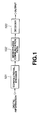
- digital information is convolved by a convolutional encoder 101, an output from the convolutional encoder 101 is supplied to a decoder 103 via a memoryless channel 102 with noises, and the output is decoded by the decoder 103.
- the transition probability of the memoryless channel 102 with noises is defined by R( ⁇
- Y 1 T ⁇ Pr ⁇ i t 0
- the input information likelihood At is a one at the time t when Y1T has been received. It is a soft-output to be determined. Practically, however, the value of ⁇ t itself is less frequently determined than its natural logarithmic value log ⁇ t. In the following description, the log ⁇ t will be referred to as "logarithmic likelihood ratio".
- the likelihood is not directly determined but a likelihood of a path not selected at each tune of the process of selection in the Viterbi decoding, in which a most likely path being sequence most likely to a received code sequence is derived, is used to determine a likelihood of a decoded bit of the most likely path, thereby determining the likelihood of each input information by approximation.
- the logarithmic likelihood ratio of the decoded bit at the time t is computed by approximation using the expression (4).
- the logarithmic likelihood ration of the decoded bit can be determined as a path-metric difference during Viterbi decoding.
- the logarithmic likelihood ratio is computed as a likelihood of the most likely path in relation to the decoded bit, namely, in the form of the expression (5) or (6):
- Y 1 T ⁇ / Pr ⁇ i t 0
- Y 1 T ⁇ ( ⁇ t )
- Y 1 T ⁇ ( 1/ ⁇ t )
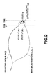
- FIG. 2 shows the merging of paths in the state k at the time j.
- a path selected is represented by P1(k, j)
- a path not selected is by P2(k, j).
- a state through which the path P1(k, j) passes at a time j-1 is represented by sl(k)
- a state through which the path P2(k, j) passes is represented by s2(k)
- a path-metric difference between the paths P1(k, j) and P2(k, j) is represented by ⁇ k(j).
- Bits decoded between the paths P1(k, j) and P2(k, j) at the time t are represented by I[P1(k,j), t] and I[P2(k,j), t], respectively, and the logarithmic likelihood ratio between the decoded bits of survivor paths in the state k when paths counted up to the time t have been selected is represented by L ⁇ t(k, j).
- the logarithmic likelihood ratio being a last soft-output is determined as L ⁇ t(k0, T).
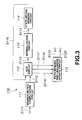
- the hardware When the SOVA is installed in a hardware, the hardware will be a SOVA decoder 110 architected as shown in FIG. 3.
- the SOVA decoder 110 includes a branch-metric computation circuit 111 to compute a branch-metric which is a Hamming distance between a received signal and path, an add compare select (ACS) circuit 112 to compare the branch-metric computed by the branch-metric circuit 111 with a state-metric being a cumulative sum of the preceding branch-metrics, a normalization circuit 113 to normalize a new state-metric signal s113 output from the ACS circuit 112, a state-metric memory circuit 114 to store a normalized state-metric signal sl 14 output from the normalization circuit 113, and a path memory and likelihood update circuit 115 supplied with path selection information s116, metric-difference information s117 and a most likely state signal s118 from the ACS circuit 112 to output a decoded data s119 and logarithmic likelihood ratio s120.
- ACS add compare select
- branch-metric computation circuit 111 When the branch-metric computation circuit 111 is supplied with a received value and a priory probability information s111, it computes a branch-metric of the received data, and outputs the result of computation as branch-metric signal s112 to the downstream ACS circuit 112.
- the ACS circuit 112 Based on the branch-metric signal s112 supplied from the branch-metric computation circuit 111 and state-metric signal s 115 supplied from the state-metric memory circuit 114, the ACS circuit 112 adds the branch-metric and state-metric to each of two paths merging in a state for comparison of the two paths. Based on the result of comparison, the ACS circuit 112 selects a more likely path and takes it as a new state-metric. The ACS circuit 112 outputs the selected path as path selection information s116 to the downstream path memory and likelihood update circuit 115. Further the ACS circuit 112 outputs a metric difference found when a path is selected in each state as a metric difference s117 to the path memory and likelihood update circuit 115.
- the ACS circuit 112 outputs a number of a having a minimum state-metric as most likely state signal s118 to the path memory and likelihood update circuit 115 and a newly obtained state-metric as new state-metric signal s113 to the downstream normalization circuit 113.
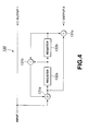
- the path selection by the ACS circuit 112 will be explained concerning a convolutional encoder with a constraint length of 3 shown in FIG. 4.
- the convolutional encoder 130 corresponds to the convolutional encoder 51 shown in FIG. 1.
- the convolutional encoder 130 includes three adders 131a, 131b and 131c and two registers 132a and 132b.
- the transition diagram (will be referred to as "trellis” hereinafter) of this convolutional encoder 130, there are always two merging paths in each state at each tune slot as shown in FIG. 5.
- the ACS circuit 112 will add a branch-metric and state-metric between a received signal and path to each of the two paths merging in a state and compare the paths for comparison with the paths. Based on the result of comparison, the ACS circuit 112 will select a more likely one of the paths.
- the normalization circuit 113 subtracts a minimum state-metric, for example, from the new state-metric signal s113 output from the ACS circuit 112 to normalize the new state-metric signal s113 to a value within a preset range, and outputs it as normalized state-metric signal s114 to the downstream state-metric memory circuit 114.
- the state-metric memory circuit 114 stores the normalized state-metric signal s114 supplied from the normalization circuit 113, and feeds it as state-metric signal s115 back to the ACS circuit 112.
- the path memory and likelihood update circuit 115 Based on the path selection information s116 output from the ACS circuit 112, the path memory and likelihood update circuit 115 stores the decoded bits on the survivor paths in each state, and updates the likelihood of each decoded bit using the metric difference information s117 output from the ACS circuit 112. Also, based on the most likely state signal s118 output from the ACS circuit 112, the path memory and likelihood update circuit 115 outputs information a constant length called "terminating length" before the information corresponding to the most likely path as decoded data s119, and likelihood information as logarithmic likelihood ratio s120.
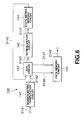
- the SOVA decoder 110 is architected quite identically to the conventional Viterbi decoder 140 which implements the Viterbi algorithm as shown in FIG. 6 except for the path memory and likelihood update circuit 115. That is, similarly to the SOVA decoder 110, the conventional Viterbi decoder 140 includes a branch-metric computation circuit 141 to compute a branch-metric, an ACS circuit 142 to add a branch-metric and state-metric to paths for comparison of the paths, a normalization circuit 143 to normalize a new state-metric signal s143 output from the ACS circuit 142, a state-metric memory circuit 144 to store a normalized state-metric signal s144 output from the normalization circuit 143, and a path memory circuit 145 supplied with path selection information s146 and metric-difference information s147 from the ACS circuit 142 to output decoded data s148.
- the conventional Viterbi decoder 140 includes a branch-metric computation circuit 141 to compute a branch-metric, an
- the SOVA decoder 110 includes the path memory and likelihood update circuit 115 to output likelihood information.
- the path memory and likelihood update circuit 115 will be described below with reference to FIGS. 7 to 9. As shown, in the path memory and likelihood update circuit 115, a memory cell MS B consisting of a selector and register is disposed on the trellis to shift, based on the path selection information s116 output from the ACS circuit 112, the content of the register when storing the decoded bit and that of the register when storing the likelihood information.
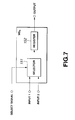
- the memory cell MS B to store the decoded bit is architected as shown in FIG. 7.
- the memory cell MS B includes a selector 151 supplied with a select signal based on the path selection information s116 output from the ACS circuit 112 to select one of two input bits based on the select signal, and a register 152 to store as decoded bits the input bits selected by the selector 151.
- the memory cell MS B to store the decoded bit is architected quite identically to the memory cell in the conventional Viterbi decoder 140 shown in FIG. 6.
- the memory cell MS P to store the likelihood information is architected as shown in FIG. 8. That is, the memory cell MS P includes a selector 153 supplied with a select signal based on the path selection information s116 output from the ACS circuit 112 to select one of two likelihood information based on the select signal, a decision circuit 154 to judge whether two decoded bits b1 and b2 supplied from the memory cell MS B to store the decoded bit are in a relation that b1 ⁇ b2 and whether two metric differences ⁇ 1 and ⁇ 2 based on the metric difference information s117 output from the ACS circuit 112 are in a relation that ⁇ 1 ⁇ ⁇ 2, a selector 155 to select the metric difference ⁇ 1 when the result of decision from the decision circuit 154 is that b1 ⁇ b2 and ⁇ 1 ⁇ ⁇ 2, and the metric difference ⁇ 2 in other cases, and a register 156 to store as likelihood information the metric difference selected by the selector 155.
- the memory cell MS B to store a decoded bit and memory cell MS P to store likelihood information are disposed as shown in FIG. 9 when the constraint length is 3. Note that these memory cells MS B and MS P are disposed correspondingly to the trellis of the convolutional encoder 130 shown in FIG. 5.
- the memory cell MS B to store a decoded bit and memory cell MS P to store likelihood information thus disposed save information on the survivor paths in each state in the registers, respectively.
- Each of the memory cells MS B and MS P is disposed in number for the terminating length.
- the SOVA decoder 110 will selection information corresponding to the most likely path and a decoded data and logarithmic likelihood ratio by selecting a most likely state output from the outputs of the last ones of the memory cells MS B and MS P , respectively.
- the memory cell MS B to store a decoded bit is architected quite identically to the path memory circuit 145 in the conventional Viterbi decoder 140 in FIG. 6.
- the SOVA decoder 110 can implement the SOVA by an actual hardware.
- the SOVA decoder 110 needs a number of memory cells MS B and a number of memory cells MS P for a number of states by the tenninating length, respectively, as shown in FIG. 9.
- the circuit scale of the memory cell MS P shown in FIG. 8 is larger than that of the memory cell MS B shown in FIG. 7, if the number of states and terminating length are larger, there will occur a problem that the circuit scale of the SOVA decoder 110 is considerably large in comparison with the conventional Viterbi decoder 140 shown in FIG. 6.
- Joeressen and Berrou proposed the same approach independently of each other by their respective articles "Joeressen, Vaupel and Mey - High-Speed VLSI Architectures for Soft-Output Viterbi Decoding, in Proc. Int. Conf. Applicat. Specific Array Processors. Oakland, CA : IEEE Computer Society Press. Aug. 1992, pp. 373-384" and "Berrou, Adde, Angui and Faudeil - A Low Complexity Soft-Output Viterbi Decoder Architecture, in Proc. IEEE Int. Conf. Commun., Geneva, Switzerland, May 1993, pp. 737-740". This approach will be called “two-step SOVA” as they call in their articles, and described below.
- the two-step SOVA With the two-step SOVA, after a Viterbi decoding for an terminating length is done once, the likelihood information is updated only for a selected path.
- the two-step SOVA will need a two-tunes larger number of memory cells to store the decoded bit than in the SOVA decoder 110 but a number of memory cells to store the likelihood information only for the terminating length. Therefore, the two-step SOVA permits to reduce the number of the memory cells to store the likelihood information. As the result, the two-step SOVA makes it possible to considerably reduce the scale of the path memory and likelihood update circuit as a whole in view of the circuit scale of the memory cell to store the likelihood information.
- FIG. 10 shows a two-step SOVA decoder.
- the two-step SOVA decoder is generally indicated with a reference 160.
- the two-step SOVA decoder 160 includes a branch-metric computation circuit 161 to compute a branch-metric, an ACS circuit 162 to the branch-metric and state-metric to each of two paths merging in a state for comparison of the two paths, a normalization circuit 163 to normalize a new state-metric signal s163 output from the ACS circuit 162, a state-metric memory circuit 164 to store a normalized state-metric signal s164 output from the normalization circuit 163, an upstream path memory circuit 165 to store decoded bits on survivor paths in each state and output delay state information s169, a path selection information delay circuit 166 to delay path delay information s166, a metric difference delay circuit 167 to delay metric difference information s167, a selection circuit 168 to select from a metric difference delay signal s171 a signal indicative of a state
- the two-step SOVA decoder 160 outputs the decoded data s174 and logarithmic likelihood ratio s175. It should be reminded here that the terminating length of the upstream path memory circuit 165 is indicated with D and that of the downstream path memory circuit 169 is with U.
- the branch-metric computation circuit 161 computes a branch-metric of the received data and outputs the result of the computation as branch-metric signal s162 to the ACS circuit 162.
- the ACS circuit 162 Based on the branch-metric signal s162 supplied from the branch-metric computation circuit 161 and state-metric signal s165 supplied from the state-metric memory circuit 164, the ACS circuit 162 adds a branch-metric and state-metric to each of two paths merging into a state for comparison of the paths, selects a more likely one of the paths based on the result of the comparison and takes it as a new state-metric.
- the ACS circuit 162 outputs the selected path as path selection information s166 to the upstream path memory circuit 165 and path selection information delay circuit 166. Also, the ACS circuit 162 outputs a metric difference found when a path is selected in each state as metric difference information s167 to the metric difference delay circuit 167.
- the ACS circuit 162 outputs a number for a state having a minimum state-metric as most likely state signal s168 to the upstream path memory circuit 165 and the newly obtained state-metric as new state-metric signal s163 to the normalization circuit 163.
- the normalization circuit 163 subtracts a minimum state-metric, for example, from the new state-metric signal s163 output from the ACS circuit 162 to normalize the new state-metric signal s163 to a value within a preset range, and outputs it as normalized state-metric signal s164 to the state-metric memory circuit 164.
- the state-metric memory circuit 164 stores the normalized state-metric signal s164 supplied from the normalization circuit 163 and feeds it as state-metric signal s165 back to the ACS circuit 162.
- the upstream path memory circuit 165 stores decoded bits on survivor paths in each state, and outputs, based on the most likely state signal s168 output from the ACS circuit 162, numbers of the states counted back over the terminating length D from the most likely path as delay state information s169 to the selection circuit 168 and downstream path memory circuit 169.
- the path selection information delay circuit 166 is provided to delay the path selection information s166 output from the ACS circuit 162 by the terminating length D of the upstream path memory circuit 165 and output it as path selection information delay signal s170 to the downstream path memory circuit 169.
- the metric difference delay circuit 167 delays the metric difference information s167 output from the ACS circuit 162 by the terminating length D of the upstream path memory circuit 165, and outputs it as metric difference delay signal s171 to the selection circuit 168.
- the selection circuit 168 Based on the delay state information s169 supplied from the upstream path memory circuit 165 and metric difference delay signal s171 supplied from the metric difference delay circuit 167, the selection circuit 168 selects a signal indicative of a state corresponding to the delay state information s169 from the metric difference delay signal s171, and outputs it as metric difference delay select signal s172 to the likelihood update circuit 170.
- the downstream path memory circuit 169 Based on the path selection information delay signal s170 supplied from the path selection information delay circuit 166, the downstream path memory circuit 169 stores decoded bits on survivor paths in each state. Also, based on the delay state information s169 output from the upstream path memory circuit 165, the downstream path memory circuit 169 outputs, as decoded bit s174, information further counted back over an terminating length U from the most likely path. Based on the delay state infonnation s169, the downstream path memory circuit 169 outputs input infonnation corresponding to the most likely path and input information corresponding to paths merging into the most likely path, only for the tenninating length, respectively, as most likely and merging path input information s173 to the likelihood update circuit 170.
- the likelihood update circuit 170 updates input information corresponding to the most likely path, that is, the likelihood of the decoded bit, based on the metric difference delay select signal s172 supplied from the selection circuit 168 and the most likely and merging path input information s173 supplied from the downstream path memory circuit 169, and outputs, as a logarithmic likelihood ratio s175, likelihood information the terminating length U before the downstream path memory circuit 169.
- the blocks of the two-step SOVA decoder 160 including the branch-metric computation circuit 161 to the upstream path memory circuit 165, are architected quite identically to those in the conventional Viterbi decoder 140 having previously been described with reference to FIG. 6.
- the downstream path memory circuit 169 and likelihood update circuit 170 will be described below with reference to FIGS. 11 to 13.
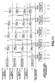
- memory cells MS B to store decoded bits shown in FIG. 7, are disposed similarly to those in the conventional Viterbi decoder 140 to shift information bits corresponding to survivor paths in each state based on the path selection information delay signal s170, and information bits are supplied from all the memory cells MS B to store the decoded bits to a selection circuit (not shown), thus providing input information corresponding to the most likely path and input bits corresponding to paths merging in the most likely path as most likely and merging path input information s173 to the likelihood update circuit 170 based on the delay state information s169 output from the upstream path memory circuit 165.
- the constraint length is 3
- the memory cells MS B provided in the downstream path memory circuit 169 to store the decoded bits and selection circuit are disposed as shown in FIG. 11.
- the likelihood update circuit 170 include memory cells MS P to store the likelihood information, architected as shown in FIG. 12. That is, each of the memory cell MS P includes a decision circuit 171 supplied with most likely path input information b1 and merging path input information b2, based on the most likely and merging path input information s173 supplied from the downstream path memory circuit 169, and also with a metric difference ⁇ 1 based on the metric difference delay select signal s172 supplied from the selection circuit 168 and likelihood information ⁇ 2 supplied from the memory cell MS P to store the preceding likelihood information, to judge whether the most likely input information b1 and merging path input information b2 are in a relation that b1 ⁇ b2 and whether the metric difference ⁇ 1 and likelihood information ⁇ 2 are in a relation that ⁇ 1 ⁇ ⁇ 2, a selector 172 to select the metric difference ⁇ 1 when the decision circuit 171 has decided that b1 ⁇ b2 and ⁇ 1 ⁇ ⁇ 2, and the likelihood information ⁇
- the memory cells MS P to store the likelihood information are disposed in an array as shown in FIG. 13, to update only the likelihood for an input bit corresponding to the most likely path determined by the upstream path memory circuit 165 for the terminating length U of the downstream path memory circuit 169, and output the likelihood information being a result of the updating as a logarithmic likelihood ratio.
- the two-step SOVA decoder 160 is adapted to determine a to-be-decoded most likely path by tracing back paths for a sufficiently long time, that is, an terminating length D, from a most likely state at a time t as shown in FIG. 14. With the metric difference and path selection information having been delayed, the two-step SOVA decoder 160 will be able to update the likelihood of only the most likely path through comparison between paths merging in the most likely path and the most likely path at a time t-D.
- the two-step SOVA decoder 160 can be embodied at a circuit scale for the same code, approximately double that of the conventional Viterbi decoder 140 shown in FIG. 6 even if the delay memory is included.
- the conventional Viterbi decoder 140 has the path memory circuits thereof formed from register arrays as in the SOVA decoder 110, for example (this will be referred to as "register shift method” hereinafter). Recently, however, a method of decoding by storing path selection information in a RAM (random-access memory) and tracing the information (will be referred to as “trace-back method” hereinafter) has been researched. The trace-back method will be discussed herebelow:
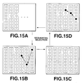
- the four single-port RAMs each having a number of bits for a number of states and a number of words for an terminating length.
- Path selection information for the number of states is supplied at every clock from the ACS circuit to the path memory circuit.
- the four RAMs have the following functions thereof switched from one to another at every clock for the terminating length.
- the function of the first RAM is to write path selection information as shown in FIG. 15, that of the second RAM is to trace based on the written path selection information without decoding as shown in FIG. 15B, that of the third RAM is to wait without access as shown in FIG. 15C, and that of the fourth RAM is to trace based on the result of tracing and output decoded bits as shown in FIG. 15D. That is, the four RAMs have their respective functions switched from one to another at every clock for the terminating length.
- the Viterbi decoder can provide a high-speed decoding. Since decoded bits determined by tracing based on the result of tracing are in a sequence opposite to the original time series of them, however, in the Viterbi decoder, the sequence of the decoded bits is corrected with the Last-in First-out (LIFO) operation to the original one before they are output.
- LIFO Last-in First-out
- the circuit scale can be considerably reduced in comparison with that when the register-shift method is adopted in the Viterbi decoder since the RAMs will need a considerably smaller area than that the registers need when the code constraint length and decoding terminating length are increased.
- the downstream path memory circuit of the two-step SOVA decoder has to read all input information bits for the terminating length at the same time while each of the RAMs operating at a high speed can be accessed only once per clock. Therefore, it is difficult to form the path memory circuit of the two-step SOVA decoder from RAMs.
- the circuit scale will be very large when the code constraint length and decoding terminating length are increased, so long as the register array is used to form the path memory circuit.
- a decoding method of decoding, in the soft-output Viterbi manner, an input convolutional code to provide a decoded data and likelihood information including steps of:
- Embodiments of the present invention relate to a decoding method and apparatus suitable for maximum likelihood decoding of a convolutional code, and more particularly, to a decoding method and apparatus suitably usable in a satellite broadcasting, etc.
- Embodiments of the present invention overcome or at least address the above-mentioned drawbacks of the prior art by providing a decoding method and apparatus to implement a SOVA decoder whose circuit scale is small or at least reduced in size and can operate at a high speed or at least at a greater speed even when the code constraint length and decoding terminating length are large.
- the above decoding method according to the present invention makes it unnecessary to read all input convolutional codes for the terminating length at the same time for acquisition of the likelihood information, and enables to store the path selection information into the random-accessible path selection information storing means. Therefore, the decoding method according to the present invention implements the trace-back method in which the path selection information stored in the random-accessible path selection information storing means is traced. Thus, even if the code constraint length and decoding- terminating length are larger than in the conventional register-shift method, the decoding can be done at a higher speed and with a smaller circuit scale.
- inventions of the present invention can provide a decoder for decoding, in the soft-output Viterbi manner, an input convolutional code to provide a decoded data and likelihood information, including:
- the decoder according to the present invention Since the minimum value of the metric difference is stored into the minimum value storing means at each transition of the convolutional code, the above decoder according to the present invention has not to read all input convolutional codes for the tenninating length at the same time for acquisition of the likelihood information, and can store the path selection information into the random-accessible path selection information storing means. Therefore, the decoding method according to the present invention implements the trace-back method in which the path selection information stored in the random-accessible path selection information storing means is traced.
- the decoder can have a small circuit scale or at least reduced in size and provide a high-speed decoding or at least decoding at a faster rate.
- FIG. 16 there is illustrated in the form of a block diagram a two-step SOVA decoder according to an embodiment of the present invention, in which the two-step soft-output Viterbi algorithm (will be referred to as "two-step SOVA” hereinafter) is adopted.
- the two-step SOVA decoder is generally indicated with a reference 10.
- FIG. 17 is a block diagram of a communications model in which the two-step SOVA decoder in FIG. 16 is adopted.
- the communications model includes a convolutional encoder 51, memoryless channel 52 and the two-step SOVA decoder 10.
- Digital information is encoded by the convolutional encoder 51 through convolutional coding, and an output from the convolutional encoder 51 is supplied to the two-step SOVA decoder 10 via the memoryless channel 52 with noises.
- the input digital information is decoded by the two-step SOVA decoder 10.
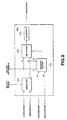
- the two-step SOVA decoder 10 includes a branch-metric computation circuit 11 to compute a branch-metric of a received data, an add compare select (ACS) circuit 12 to add a branch-metric and state-metric together for comparison, a normalization circuit 13 to normalize a new state-metric signal s13 output from the ACS circuit 12, a state-metric memory circuit 14 to store a normalized state-metric signal s14 output from the normalization circuit 13, a metric difference memory circuit 15 to delay a metric difference information s17, and a path memory and likelihood update circuit 16 to output a decoded data s20 and logarithmic likelihood ratio s21.
- ACS add compare select
- the two-step SOVA decoder 10 will output the decoded data s20 being a result of decoding and the logarithmic likelihood ratio s21.
- the branch-metric computation circuit 11 computes a branch-metric of the received data and outputs a result of this computation as branch-metric signal s12.
- the ACS circuit 12 Based on the branch-metric signal s12 supplied from the branch-metric computation circuit 11 and state-metric signal s15 supplied from the state-metric memory circuit 14, the ACS circuit 12 adds the branch-metric and state-metric to two paths merging into a state (transition) for comparison, selects a more likely one of the paths based on a result of the comparison, and takes it as a new state-metric.
- the ACS circuit 12 outputs the selected path as path selection information s16 to the downstream path memory and likelihood update circuit 16. Also, the ACS circuit 12 outputs to the downstream metric difference delay circuit 15 a metric difference when a path is selected in each state as metric difference information s17.
- the ACS circuit 12 outputs a number of a state having a minimum state-metric as most likely state signal s18 to the downstream path memory and likelihood update circuit 16. In addition, the ACS circuit 12 outputs to the downstream normalization circuit 13 a newly acquired state-metric as new state-metric signal s13.
- the normalization circuit 13 subtracts a minimum state-metric, for example, from the new state-metric signal s13 output from the ACS circuit 12 to normalize the new state-metric signal s13 to a value within a preset range, and outputs it as normalized state-metric signal s14 to the downstream state-metric memory circuit 14.
- the state-metric memory circuit 14 stores the nonnalizer state-metric signal s14 supplied from the normalization circuit 13 and feeds it as the state-metric signal s15 back to the ACS circuit 12.
- the metric difference delay circuit 15 will delay the metric difference information s17 output from the ACS circuit 12 by 4D, and outputs it as metric difference delay signal s19 to the downstream path memory and likelihood update circuit 16.
- the path memory and likelihood update circuit 16 stores decoded bits of survivor paths in each state based on the path selection information s16 output from the ACS circuit 12 while updating the likelihood of the decoded bits of the most likely path using the metric difference delay information s19 output from the metric difference delay circuit 15. Also, the path memory and likelihood update circuit 16 outputs the decoded data s20 and logarithmic likelihood ratio s21 based on the most likely state signal s18 output from the ACS circuit 12.
- the transition diagram (will be referred to as "trellis" hereinafter) used for decoding a code whose constraint length is 3 with an terminating length of 5 is as shown in FIG. 18. It is assumed here that the most likely path is a one whose bits are all zeros (0). To acquire a soft-output SOVA at a time t in this trellis, it is necessary to acquire a minimum value of the metric difference ⁇ of a path for which the input at the time t is 1. In this case, it is necessary to acquire a minimum value min (a, c, d) of a, c and d.
- the minimum value min(a, c, d) can be acquired by selecting minimum values of the contents d and min (a, c) corresponding to the states 01 and 11.
- a circuit to store minimum values of the metric difference ⁇ in each state and update them one after another in an order contrary to the time-series order can be implemented as shown in FIGS. 19 and 20 by taking the trellis connection in consideration.
- the minimum metric difference ( ⁇ ) memory circuit 20 includes metric difference ( ⁇ ) update cells 21a, 21b, 21c and 21d to update the metric difference.
- the update cells 21a to 21d store minimum values of states 00, 01, 10 and 11, respectively.
- the states to which the metric difference ( ⁇ ) update cells 21a to 21d correspond, respectively, will be referred to as "cell-corresponding states", respectively.
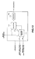
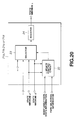
- Each of the update cells 21a to 21d in the minimum metric difference ( ⁇ ) memory circuit 20 includes a metric difference ( ⁇ ) update control circuit 22, selector 23 and register 24 as shown in FIG. 20.
- the metric difference ⁇ is a metric difference between the most likely path and paths existing concurrently and merging into the most likely path
- ⁇ 1 and ⁇ 2 indicate minimum values, respectively, of the metric difference so far stored in the metric difference ( ⁇ ) update cells for two states (will be referred as "possible states” hereafter) contiguous from the states to which the cells correspond, respectively, at a next time.
- ⁇ indicates a maximum value which can be represented with a number of bits used to represent a metric difference ⁇ .
- the metric difference ( ⁇ ) update cells 21a to 21d Under the control of the metric difference ( ⁇ ) update control circuit 22, the metric difference ( ⁇ ) update cells 21a to 21d initialize only the states corresponding to the cells and through which the most likely path passes to ⁇ , and other states to ⁇ . Thereafter, under the control of the metric difference ( ⁇ ) update control circuit 22, the metric difference ( ⁇ ) update cells 21a to 21d select a metric difference ⁇ by means of the selector 23 when the cell-corresponding states are those through which the most likely path passes, and update the metric difference ⁇ based on path selection information for a next possible state, as will be described below, when the cell-corresponding states are other than those through which the most likely path passes.
- the metric difference ( ⁇ ) update cells 21a to 21d select min ( ⁇ 1, ⁇ 2) by means of the selector 23 under the control of the metric difference ( ⁇ ) update control circuit 22 when both paths going to a next possible state survive.
- the metric difference ( ⁇ ) update cells 21a to 21d select, by means of the selector 23, min ( ⁇ 1, ⁇ 2) when one of the paths going to the next possible state survives and the other not surviving is going to a state through which the most likely path passes, and either ⁇ 1 or ⁇ 2 for a selected path when one of the paths going to the next possible state survives and the other not surviving is going to other than a state through which the most likely path passes.
- the metric difference ( ⁇ ) update cells 21a to 21d select, by means of the selector 23, one of the values ⁇ 1 or ⁇ 2 which is for the state through which the most likely path passes, when both the paths going to the next possible states do not survive and one of the next possible states is a one through which the most likely path passes, and ⁇ when both the paths going to the next possible state do not survive and one of the next possible states is not a one through which the most likely path passes.
- Each of the metric difference ( ⁇ ) update cells 21a to 21d stores into the register 24 a value selected by the selector 23 as a minimum ⁇ of the state.
- the register 24 provided in the minimum metric difference ( ⁇ ) memory circuit 20 for each state stores a value as shown in FIG. 21.
- the register 24 for each state a minimum value of the metric difference for the most likely path in the process of tracing back the baths.
- the two-step SOVA decoder 10 can be constructed from RAMs as will be described below.
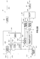
- the path memory and likelihood update circuit 16 in the two-step SOVA decoder 10 is architected as shown in FIG. 22. More specifically, the path memory and likelihood update circuit 16 includes a control circuit 31 supplied with the most likely state signal s18 and trace result signal s41 to output a control signal s31 and trace control signal s32, eight RAMs 32a to 32h to store path selection information, a trace circuit 33 to output the trace result signal s41, a trace result memory circuit 34 to store a result of tracing of the most likely path and output it as delayed trace result signal s42, a most likely path metric difference ( ⁇ ) memory circuit 35 to select and store the metric difference ⁇ of the most likely path and output it as a delayed most likely metric difference ( ⁇ ) signal s43, a selection circuit 36 to select path selection information for use to update the minimum metric difference ⁇ , minimum metric difference ( ⁇ ) memory circuits 37a and 37b constructed similarly to the minimum metric difference ( ⁇ ) memory circuit 20 to store the minimum values, a selection circuit 38
- path selection information s16 supplied from the ACS circuit 12 is written into the RAMs 32a, 32b, ..., 32h according to the control signal s31 output from the control circuit 31.
- path selection information s33, s34, ..., s40 are read from the RAMs 32a, 32b, ..., 32h and supplied to the trace circuit 33 according to the control signal s31 output from the control circuit 31.
- the trace circuit 33 traces based on path selection information s33, s34, ..., s40 according to the trace control signal s32 supplied from the control circuit 31, and supplies the result of tracing as the trace result signal s41 to the control circuit 31 and trace results memory circuit 34.
- the control circuit 31 Based on the trace result signal s41 supplied from the trace circuit 33 and most likely state signal s18 supplied from the ACS circuit 12, the control circuit 31 produces a trace control signal s32 and supplies it to the trace circuit 33. Also the control circuit 31 supplies the produced trace control signals s32 to the output buffer 39 as well.
- the output buffer 39 determines and stores decoded bits based on the trace control signal s32 supplied from the control circuit 31 and outputs a decoded data s20 at a time when the logarithmic likelihood ratio s21 is output from the LIFO circuit 40 which will further be described later.
- the trace result memory circuit 34 stores the result of tracing the most likely path based on the trace result signal s41 supplied from the trace circuit 33. Then, according to the control signal s31 supplied from the control circuit 31, the trace result memory circuit 34 outputs a result of tracing the most likely path, stored therein, as delayed trace result signal s42 to the downstream most likely metric difference ( ⁇ ) memory circuit 35, minimum metric difference ( ⁇ ) memory circuits 37a and 37b and selection circuit 38.
- ⁇ most likely metric difference
- ⁇ minimum metric difference
- the most likely path metric difference ( ⁇ ) memory circuit 35 Based on the metric difference delay signal s19 supplied from the metric difference delay circuit 15 and delayed trace result signal s42 supplied from the trace result memory circuit 34, the most likely path metric difference ( ⁇ ) memory circuit 35 selects and stores a most likely path metric difference ⁇ from the metric difference delay signal s19. Then, the most likely path metric difference ( ⁇ ) memory circuit 35 outputs a metric difference ⁇ stored therein as a most likely metric difference ( ⁇ ) signal s43 to the downstream minimum metric difference ( ⁇ ) memory circuits 37a and 37b according to the control signal s31 supplied from the control circuit 31.
- the selection circuit 36 selects path selection information for use to update the minimum metric difference ⁇ according to the control signal s31 supplied from the control circuit 31. Then the selection circuit 36 outputs the selected path selection information as path selection information s44 and s45 to the downstream minimum metric difference ( ⁇ ) memory circuits 37a and 37b, respectively.
- the minimum metric difference ( ⁇ ) memory circuits 37a and 37b select and store a minimum metric difference ⁇ in each state and output it as state minimum metric difference (A) signals s46 and s47 to the downstream selection circuit 38.
- the selection circuit 38 selects a state minimum metric difference ( ⁇ ) signal for use to acquire a soft-output from the state minimum metric difference ( ⁇ ) signals s46 and s47, determines minimum values for the most likely path and paths difference in number of input bits from the most likely path, and outputs it as logarithmic likelihood ratio information s48 to the downstream LIFO circuit 40.
- the logarithmic likelihood ratio information s48 is determined in an order contrary to the actual time-series order.
- the LIFO circuit 40 stores the logarithmic likelihood ratio information s48 ordered contrary to the actual time-series order once, corrects it into the original time-series order and then outputs as a logarithmic likelihood ratio s21.
- the path memory and likelihood update circuit 16 outputs the decoded data s20 and logarithmic likelihood ratio s21.
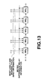
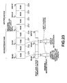
- the eight RAMs 32a, 32b, ..., 32h provided in the path memory and logarithmic likelihood update circuit 16 work as shown in FIG. 23. They are grouped as an upstream group of RAMs 32a, 32b, 32c and 32d and a downstream group of RAMs 32e, 32f, 32g and 32h.
- the upstream group of the RAMs 32a to 32d serves as an upstream path memory circuit in the conventional two-step SOVA decoder, and the downstream group of the RAMs 32e to 32h works are the downstream path memory circuit.
- the upstream group of the RAMs 32a to 32d works like the Viterbi decoder based on the conventional trace-back method.
- the path memory and likelihood update circuit 16 first the path selection information s16 supplied from the ACS circuit 12 is written into the RAM 32a in the time-series order.
- the path selection information s34 is read from the RAM 32b in an order contrary to the time-series order and paths for the terminating length are traced.
- the path memory and likelihood update circuit 16 no access is made to the RAM 32c but the path selection information s36 is read from the RAM 32d in an order contrary to the time-series order.
- the RAM 32d effects a trace for the terminating length, starting at the trace start point based on a result of the trace for the terminating length, to determine a most likely path and output decoded bits.
- the downstream group of RAMs 32e to 32h uses the minimum metric difference ( ⁇ ) memory circuits 37a and 37b to play the role of the downstream path memory circuit in the conventional two-step SOVA decoder.
- the path selection information s38 is read from the RAM 32f in an order contrary to the time-series order.
- the metric difference ⁇ is read from the most likely path metric difference ( ⁇ ) memory circuit 35 in an order contrary to the time-series order and supplied as delayed most likely metric difference ( ⁇ ) signal s43 to the minimum metric difference ( ⁇ ) memory circuits 37a and 37b which will first be initialized to update the minimum metric difference ⁇ in each state at each time.
- the path memory and likelihood update circuit 16 no access is made to the RAM 32g but the path selection information s40 is read from the RAM 32h in an order contrary to the time-series order.
- the metric difference ⁇ is read from the most likely path metric difference ( ⁇ ) memory circuit 35 as well in an order contrary to the time-series order, and supplied as delayed most likely metric difference ( ⁇ ) signal s43 to the minimum metric difference ( ⁇ ) memory circuits 37a and 37b.
- the minimum metric difference ( ⁇ ) memory circuits 37a and 37b will update the minimum metric difference ⁇ in each state at each time, starting with the minimum metric difference ⁇ having been updated for the terminating length.
- the RAMs 32a, 32b, ..., 32h working as in the above have their respective functions shifted one by one each time an operation for the terminating length is done. Namely, the RAM 32b will, when in a next operation, play the role the RAM 32a has played, and the RAM 32c will, when in a next operation, play the tole the RAM 32b has played. Subsequently, the RAM roles are switched similarly, and the RAM 32a will, when in a next operation, play the role the RAM 32h has played.
- the two-step SOVA decoder 10 can use the RAMs for its intended purpose.
- the two-step SOVA decoder 10 includes the minimum metric difference ( ⁇ ) memory circuits 37a and 37b to store the minimum value of the metric difference ⁇ in each state and thus has not to read all input information bits for the terminating length at the same tune when a soft-output is determined in the downstream path memory circuit. Therefore, the two-step SOVA decoder 10 stores path selection information s16 in the RAMs 32a to 32h, and traces the information. Thus, it can work at a high speed with a small circuit scale even when the code constraint length and terminating length are larger than in the conventional register-shift method.
- ⁇ minimum metric difference
- the present invention is not limited to the above-mentioned embodiments but applied even when the code constraint length and terminating length are of arbitrary values, respectively, not when a code whose constraint length is 3 is decoded with an terminating length of 5. Needless to say, the present invention can appropriately be modified without departing from the spirit and scope of the Claims given later.
Landscapes
- Physics & Mathematics (AREA)
- Probability & Statistics with Applications (AREA)
- Engineering & Computer Science (AREA)
- Theoretical Computer Science (AREA)
- Computer Networks & Wireless Communication (AREA)
- Signal Processing (AREA)
- Error Detection And Correction (AREA)
- Detection And Prevention Of Errors In Transmission (AREA)
Applications Claiming Priority (2)
| Application Number | Priority Date | Filing Date | Title |
|---|---|---|---|
| JP11150751A JP2000341140A (ja) | 1999-05-28 | 1999-05-28 | 復号方法及び復号装置 |
| JP15075199 | 1999-05-28 |
Publications (2)
| Publication Number | Publication Date |
|---|---|
| EP1056213A2 true EP1056213A2 (de) | 2000-11-29 |
| EP1056213A3 EP1056213A3 (de) | 2004-07-07 |
Family
ID=15503631
Family Applications (1)
| Application Number | Title | Priority Date | Filing Date |
|---|---|---|---|
| EP00304467A Withdrawn EP1056213A3 (de) | 1999-05-28 | 2000-05-25 | Dekodierungsverfahren und Vorrichtung |
Country Status (4)
| Country | Link |
|---|---|
| US (1) | US6668026B1 (de) |
| EP (1) | EP1056213A3 (de) |
| JP (1) | JP2000341140A (de) |
| KR (1) | KR20010014975A (de) |
Families Citing this family (12)
| Publication number | Priority date | Publication date | Assignee | Title |
|---|---|---|---|---|
| JP4190136B2 (ja) * | 2000-06-27 | 2008-12-03 | 富士通株式会社 | データ記録再生装置 |
| KR100487183B1 (ko) * | 2002-07-19 | 2005-05-03 | 삼성전자주식회사 | 터보 부호의 복호 장치 및 방법 |
| GB2401290B (en) * | 2003-04-29 | 2007-02-28 | Ubinetics Ltd | Decoders |
| JP4432781B2 (ja) * | 2005-01-17 | 2010-03-17 | 株式会社日立製作所 | 誤り訂正復号器 |
| US7502982B2 (en) | 2005-05-18 | 2009-03-10 | Seagate Technology Llc | Iterative detector with ECC in channel domain |
| US7395461B2 (en) | 2005-05-18 | 2008-07-01 | Seagate Technology Llc | Low complexity pseudo-random interleaver |
| US7360147B2 (en) * | 2005-05-18 | 2008-04-15 | Seagate Technology Llc | Second stage SOVA detector |
| KR20080012434A (ko) * | 2006-08-03 | 2008-02-12 | 삼성전자주식회사 | 입력 메시지의 특성을 고려한 복호 장치 및 방법 |
| US7716564B2 (en) * | 2007-09-04 | 2010-05-11 | Broadcom Corporation | Register exchange network for radix-4 SOVA (Soft-Output Viterbi Algorithm) |
| RU2010149150A (ru) * | 2010-12-02 | 2012-06-10 | ЭлЭсАй Корпорейшн (US) | Способ и устройство (варианты) для декодирования с упреждающим исправлением ошибок по алгоритму витерби radix-4 |
| JP6155959B2 (ja) * | 2013-08-19 | 2017-07-05 | 富士通株式会社 | 復号化装置、及び、復号化方法 |
| US9588772B2 (en) | 2015-02-20 | 2017-03-07 | Kabushiki Kaisha Toshiba | Memory controller and decoding method |
Family Cites Families (4)
| Publication number | Priority date | Publication date | Assignee | Title |
|---|---|---|---|---|
| FR2675968B1 (fr) * | 1991-04-23 | 1994-02-04 | France Telecom | Procede de decodage d'un code convolutif a maximum de vraisemblance et ponderation des decisions, et decodeur correspondant. |
| US5390198A (en) * | 1993-05-26 | 1995-02-14 | The Boeing Company | Soft decision viterbi decoder for M-ary convolutional codes |
| JPH09232973A (ja) * | 1996-02-28 | 1997-09-05 | Sony Corp | ビタビ復号器 |
| JP3322155B2 (ja) * | 1997-03-05 | 2002-09-09 | 日本電気株式会社 | データ再生装置 |
-
1999
- 1999-05-28 JP JP11150751A patent/JP2000341140A/ja not_active Withdrawn
-
2000
- 2000-05-25 US US09/578,582 patent/US6668026B1/en not_active Expired - Fee Related
- 2000-05-25 EP EP00304467A patent/EP1056213A3/de not_active Withdrawn
- 2000-05-26 KR KR1020000028697A patent/KR20010014975A/ko not_active Ceased
Also Published As
| Publication number | Publication date |
|---|---|
| JP2000341140A (ja) | 2000-12-08 |
| KR20010014975A (ko) | 2001-02-26 |
| EP1056213A3 (de) | 2004-07-07 |
| US6668026B1 (en) | 2003-12-23 |
Similar Documents
| Publication | Publication Date | Title |
|---|---|---|
| US6697443B1 (en) | Component decoder and method thereof in mobile communication system | |
| EP0967730B1 (de) | Faltungsdekodierer mit geänderter Metrik | |
| JP3900637B2 (ja) | ビタビ復号装置 | |
| JP3747604B2 (ja) | ビタビ復号装置 | |
| JP3246484B2 (ja) | ターボデコーダ | |
| EP1056213A2 (de) | Dekodierungsverfahren und Vorrichtung | |
| US20050149838A1 (en) | Unified viterbi/turbo decoder for mobile communication systems | |
| JPWO2000052833A1 (ja) | 最大事後確率復号方法及び装置 | |
| US7373582B2 (en) | Apparatus and method for turbo decoding using a variable window size | |
| KR100336246B1 (ko) | 디지탈프로세서및코-프로세서를구비한집적회로 | |
| US7003041B2 (en) | Device and method for decoding turbo codes | |
| JP3233847B2 (ja) | ビタビ復号方法及びビタビ復号回路 | |
| EP1521374A1 (de) | Maximale a posteriori Wahrscheinlichkeitsdecodierung (MAP Decodierung) | |
| US8489972B2 (en) | Decoding method and decoding device | |
| JP2002217748A (ja) | 誤り訂正復号器 | |
| JP2000341137A (ja) | 復号装置 | |
| RU2247471C2 (ru) | Компонентный декодер и способ декодирования в системе мобильной связи | |
| KR20020066556A (ko) | 터보 코드 복호화 장치 및 방법 | |
| JP2006115534A (ja) | 誤り訂正符号の復号方法、そのプログラム及びその装置 | |
| CN102282771A (zh) | 解码装置和解码设备 | |
| KR100459414B1 (ko) | 터보 복호기의 복호 방법 | |
| KR20040065841A (ko) | 비터비 복호기의 트레이스백 연산방법 | |
| JP2001094440A (ja) | 誤り訂正復号器 | |
| WO2001029973A1 (en) | Trellis backtrace decoder | |
| HK1165111B (en) | Decoding method |
Legal Events
| Date | Code | Title | Description |
|---|---|---|---|
| PUAI | Public reference made under article 153(3) epc to a published international application that has entered the european phase |
Free format text: ORIGINAL CODE: 0009012 |
|
| AK | Designated contracting states |
Kind code of ref document: A2 Designated state(s): AT BE CH CY DE DK ES FI FR GB GR IE IT LI LU MC NL PT SE |
|
| AX | Request for extension of the european patent |
Free format text: AL;LT;LV;MK;RO;SI |
|
| PUAL | Search report despatched |
Free format text: ORIGINAL CODE: 0009013 |
|
| AK | Designated contracting states |
Kind code of ref document: A3 Designated state(s): AT BE CH CY DE DK ES FI FR GB GR IE IT LI LU MC NL PT SE |
|
| AX | Request for extension of the european patent |
Extension state: AL LT LV MK RO SI |
|
| 17P | Request for examination filed |
Effective date: 20041118 |
|
| AKX | Designation fees paid |
Designated state(s): DE FR GB |
|
| 17Q | First examination report despatched |
Effective date: 20050512 |
|
| GRAP | Despatch of communication of intention to grant a patent |
Free format text: ORIGINAL CODE: EPIDOSNIGR1 |
|
| RAP1 | Party data changed (applicant data changed or rights of an application transferred) |
Owner name: SONY CORPORATION |
|
| STAA | Information on the status of an ep patent application or granted ep patent |
Free format text: STATUS: THE APPLICATION IS DEEMED TO BE WITHDRAWN |
|
| 18D | Application deemed to be withdrawn |
Effective date: 20061201 |